Table of Contents
Advertisement
Quick Links
Temperature/Resistance /Voltage
All Hayward controls use a 10K thermistor sensors. When disconnected from the
control, the sensor will read 10K ohms at 25ºC/77ºF. Refer to the chart below for
the resistance at other temperatures. For a given temperature, the resistance
reading should be accurate to ±1%. For a given resistance reading, the tempera-
ture reading should be accurate to ±0.5ºF. All voltage measurements (DC) must
be made with the sensor connected to the control and should be accurate to ± 2%.
°F
Ohms
Volts °F
Ohms
Volts
1
82,719
4.46
41
25,391
3.59
2
80,142
4.45
42
24,704
3.56
3
77,656
4.43
43
24,037
3.53
4
75,255
4.41
44
23,391
3.50
5
72,937
4.40
45
22,764
3.47
6
70,698
4.38
46
22,156
3.45
7
68,535
4.36
47
21,566
3.42
8
66,447
4.35
48
20,993
3.39
9
64,428
4.33
49
20,438
3.36
10
62,479
4.31
50
19,900
3.33
11
60,595
4.29
51
19,377
3.30
12
58,774
4.27
52
18,870
3.27
13
57,014
4.25
53
18,377
3.24
14
55,313
4.23
54
17,899
3.21
15
53,669
4.21
55
17,435
3.18
16
52,078
4.19
56
16,985
3.15
17
50,541
4.17
57
16,548
3.12
18
49,054
4.15
58
16,123
3.09
19
47,616
4.13
59
15,711
3.06
20
46,225
4.11
60
15,310
3.02
21
44,879
4.09
61
14,921
2.99
22
43,577
4.07
62
14,543
2.96
23
42,318
4.04
63
14,176
2.93
24
41,099
4.02
64
13,820
2.90
25
39,919
4.00
65
13,473
2.87
26
38,777
3.97
66
13,136
2.84
27
37,671
3.95
67
12,809
2.81
28
36,601
3.93
68
12,491
2.78
29
35,565
3.90
69
12,182
2.75
30
34,561
3.88
70
11,882
2.72
31
33,590
3.85
71
11,589
2.68
32
32,648
3.83
72
11,305
2.65
33
31,737
3.80
73
11,029
2.62
34
30,853
3.78
74
10,761
2.59
35
29,998
3.75
75
10,500
2.56
36
29,169
3.72
76
10,246
2.53
37
28,365
3.70
77
9,999
2.50
38
27,587
3.67
78
9,758
2.47
39
26,832
3.64
79
9,525
2.44
40
26,100
3.61
80
9,297
2.41
620 Division St.
Elizabeth, NJ 07207
°F
Ohms
Volts
°F
Ohms
Volts
81
9,076
2.38
121
3,679
1.34
82
8,861
2.35
122
3,602
1.32
83
8,651
2.32
123
3,527
1.30
84
8,447
2.29
124
3,454
1.28
85
8,249
2.26
125
3,382
1.26
86
8,056
2.23
126
3,312
1.24
87
7,867
2.20
127
3,244
1.22
88
7,684
2.17
128
3,177
1.21
89
7,506
2.14
129
3,112
1.19
90
7,333
2.12
130
3,049
1.17
91
7,164
2.09
131
2,987
1.15
92
6,999
2.06
132
2,926
1.13
93
6,839
2.03
133
2,867
1.11
94
6,683
2.00
134
2,809
1.10
95
6,530
1.98
135
2,752
1.08
96
6,382
1.95
136
2,697
1.06
97
6,238
1.92
137
2,643
1.05
98
6,097
1.89
138
2,591
1.03
99
5,960
1.87
139
2,539
1.01
100
5,827
1.84
140
2,489
1.00
101
5,697
1.81
141
2,440
0.98
102
5,570
1.79
142
2,392
0.97
103
5,446
1.76
143
2,345
0.95
104
5,326
1.74
144
2,299
0.93
105
5,208
1.71
145
2,254
0.92
106
5,094
1.69
146
2,210
0.90
107
4,982
1.66
147
2,167
0.89
108
4,873
1.64
148
2,125
0.88
109
4,767
1.61
149
2,084
0.86
110
4,664
1.59
150
2,044
0.85
111
4,563
1.57
151
2,005
0.84
112
4,464
1.54
152
1,966
0.82
113
4,368
1.52
153
1,929
0.81
114
4,274
1.50
154
1,892
0.80
115
4,183
1.47
155
1,856
0.78
116
4,094
1.45
156
1,821
0.77
117
4,007
1.43
157
1,787
0.76
118
3,922
1.41
158
1,753
0.75
119
3,839
1.39
159
1,720
0.73
120
3,758
1.37
160
1,688
0.72
092008F RevG
Copyright © 2010 Hayward Inc.
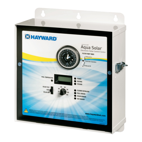
Aqua Solar
Electronic Solar Control Center
Operation and Installation
Manual
AQ-SOL-LV
AQ-SOL-LV-TC
AQ-SOL-LV-SP
www.haywardnet.com
Advertisement
Table of Contents

Related Manuals for Hayward Aqua Solar


Summary of Contents for Hayward Aqua Solar
- Page 1 Temperature/Resistance /Voltage All Hayward controls use a 10K thermistor sensors. When disconnected from the control, the sensor will read 10K ohms at 25ºC/77ºF. Refer to the chart below for Aqua Solar the resistance at other temperatures. For a given temperature, the resistance reading should be accurate to ±1%.
- Page 2 No wholesaler, agent, dealer, contractor, or other person is authorized to give any warranty on behalf of Hayward. This warranty is void if the product has been altered in any way after leaving smaller than 8 AWG US/ 6 AWG Canada.
- Page 3 Wiring Wiring Wiring Wiring ..................4 indication only occurs when the "AUX" sensor is being used for recirculate freeze protection. When the Aux sensor is shorted, the Aqua Solar will use the "SOLAR" Jumper Settings Jumper Settings Jumper Settings Jumper Settings Jumper Settings ..............9...
- Page 4 Check main power circuit breakers. Check to see if the Aqua Solar power is connected to the LOAD side of the filter pump timer, in which case the Aqua Solar will only be on well as programmable set point temperature. Automatic nocturnal cooling (for pools when the filter pump is on.
- Page 5 COOLING: A high voltage relay for filter pump control is usually required to imple- ment this function. If Cooling is enabled, the Aqua Solar will cool the pool by turning The “Heating” LED will show when the pool is being solar heated. If your pool has...
- Page 6 7 (bottom) for typical wiring. filter pump running even though the time clock is “off” FILTER PUMP: The function of this relay varies with the model of the Aqua Solar. If the "Solar Override" is enabled (see "Jumper Settings"), the Aqua Solar will override TEMPERATURE DISPLAY the time clock and turn the filter pump on when there is a call for solar heating.
- Page 7 Mounting The Aqua Solar is designed for outdoor use. Mount the enclosure vertically with the Aqua Solar knockouts facing downward. For safety, the Aqua Solar must be a minimum of 5 feet (horizontally) from the pool or spa. (AQ-SOL-LV-TC) Power input Turn off power at circuit breaker before wiring.
- Page 8 AQ-SOL-LV: For most systems, simply connect the Aqua Solar power to the LOAD side of the filter pump timer. If the Aqua Solar is connected to LINE power (typically when "Recirculate Freeze" or "Solar Override" features are also being used), then...
Need help?
Do you have a question about the Aqua Solar and is the answer not in the manual?
Questions and answers