
Related Manuals for GW Instek LCR-915 Series


Summary of Contents for GW Instek LCR-915 Series
- Page 1 Hand-held LCR Meter LCR-914/915/916 Series USER MANUAL GW INSTEK PART NO. 82CR-91600MA1 ISO-9001 CERTIFIED MANUFACTURER...
- Page 2 This manual contains proprietary information, which is protected by copyright. All rights are reserved. No part of this manual may be photocopied, reproduced or translated to another language without prior written consent of Good Will company. The information in this manual was correct at the time of printing.
-
Page 3: Safety Information
LCR-914/915/916 User Manual Warning Safety sheet ........ -
Page 4: Maintenance
LCR-914/915/916 User Manual CAUTION ˙ Never connect a source of voltage that could result in damage to the meter and the equipment under test. ˙ Do not expose the Meter to extremes in temperature or high humidity. Symbols as Marked on the Meter and the Instruction Manual Risk of electric shock See instruction manual... -
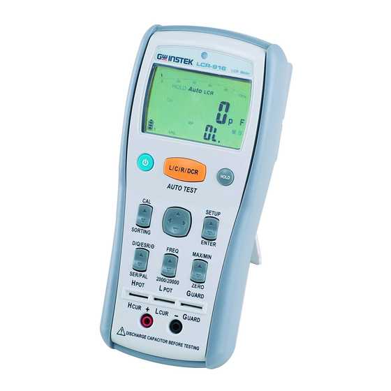
Page 5: Meter Description
LCR-914/915/916 User Manual Meter Description Front Panel Illustration 1. LCD display: 20000/2000 counts. 2. Function buttons. 3. 5-Wire input terminal for SMD test probe or DIP part. 4. 2-Wire input terminal for Alligator Clips. -
Page 6: Package Contents
LCR-914/915/916 User Manual Package Contents 1. 5V AC Adapter (only LCR-916). 2. USB Cable (only LCR-916). 3. Shorting Cube. 4. SMD Test Probe (only LCR-916). 5. Alligator Clip Set. 6. Hanging Kit (only LCR-915/916). -
Page 7: Measuring Principles
LCR-914/915/916 User Manual Measuring Principles ... - Page 8 LCR-914/915/916 User Manual Phase Drawing...
- Page 9 LCR-914/915/916 User Manual Making 5-Wire Measurements with the SMD Test Probe...
- Page 10 LCR-914/915/916 User Manual Making 4-Wire Measurements with the 5-Wire Terminal Making 2-Wire Measurements with the Alligator Clip Set...
- Page 11 LCR-914/915/916 User Manual Measuring L/C/R/DCR • Press the L/C/R/DCR button to select the measurement function. • Press the L/C/R/DCR button for 2 seconds to enter the Auto L/C/R function.
- Page 12 LCR-914/915/916 User Manual Measuring D/Q/ESR/θ θ button to select the measurement • Press the D/Q/ESR/ function.
- Page 13 LCR-914/915/916 User Manual Selecting the Test Frequency • Press the FREQ button to select the test frequency. • The selectable frequency range depends on the model: LCR-914: 100Hz, 120Hz, 1kHz. LCR-915: 100Hz, 120Hz, 1kHz, 10kHz. LCR-916: 100Hz, 120Hz, 1kHz, 10kHz, 100kHz.
- Page 14 LCR-914/915/916 User Manual Selecting the Series / Parallel Measurement Function • At the L/C/R measuring function, it defaults to Auto Series / Parallel measuring function. • Press the SER/PAL button to select the measuring function.
- Page 15 LCR-914/915/916 User Manual Selecting the Display Count • Press the 2000 /20000 button to select the display count. Zero The Zero mode records the current input value as a reference and displays the reference on the sub display. Any inputs after this will be subtracted from the reference value and displayed on the main display.
-
Page 16: Display Hold
LCR-914/915/916 User Manual Display Hold • Press the HOLD button to hold the reading on the meter, press the button again to return. Display MAX/MIN The MAX/MIN mode records the maximum and the minimum input values. When the inputs go below the recorded minimum value or above the recorded maximum value, the meter beeps and records the new value. - Page 17 LCR-914/915/916 User Manual Calibratation In order to achieve the best measurement results, calibration is essential. To calibrate the meter, press the CAL button.
- Page 18 LCR-914/915/916 User Manual When “OPEn” appears on the sub display, make the terminal or the SMD test probe open, and press the CAL button to start the open calibration. About 30 seconds later, the result of the open calibration appears on the main display. If the result is “pass”, press the CAL button to proceed to the next step.
- Page 19 LCR-914/915/916 User Manual When “Srt” appears on the sub display, short the terminals or the SMD test probe, and then press the CAL button to start the short calibration. About 30 seconds later, the result of the short calibration appears on the main display. If the result is “pass”, press the CAL button to complete the calibration.
- Page 20 LCR-914/915/916 User Manual Sorting To check the accuracy of a part, press the SORTING button to enter the sorting mode. The sorting result appears on the main display, and the current value appears on the sub display.
- Page 21 LCR-914/915/916 User Manual The default sorting standard value is the current value, and the default tolerance is ±1.0%. Setup Sorting Standard To setup the sorting standard value, follow the steps below: 1. Press the SETUP button to enter the setup mode. 2.
-
Page 22: Battery Replacement
LCR-914/915/916 User Manual Battery Replacement Refer to the following figure to replace the batteries : Caution ˙ Replace the batteries as soon as the low battery indicator appears, to avoid false reading. ˙ 1.5V x 4 alkaline batteries. External Power Source Save battery power by using the external power source. -
Page 23: Specifications
LCR-914/915/916 User Manual Specifications General Specifications Maximum voltage applied to any terminal: or 30V Display: 2000/20000 counts Overrange Indication: OL Battery Life: 80 hours Low Battery Indicator: " " is displayed when the battery voltage drops below the operating voltage. Low battery voltage: Approx. -
Page 24: Electrical Specifications
LCR-914/915/916 User Manual Shock Vibration: Sinusoidal vibration per MIL-T- 28800E (5 ~ 55 Hz, 3g maximum). Drop Protection: 4 feet drop to hardwood on concrete floor. Indoor Use. Electrical Specifications (1) Test Frequency Range Resolution Accuracy 100.00 Hz 0.01 Hz ±... - Page 25 LCR-914/915/916 User Manual (4) Inductance Frequency Range Accuracy 20.000mH ± (0.5% + 5d) 200.00mH 2000.0mH ± (0.2% + 2d) 100Hz 20.000H 120Hz 200.00H 2000.0H ± (0.5% + 2d) 20.000kH ± (1.0% + 2d) 2000.0uH ± (0.5% + 5d) 20.000mH 200.00mH ±...
- Page 26 LCR-914/915/916 User Manual (5) Capacitance Frequency Range Accuracy 2000.0pF ± (0.5% + 5d) 20.000nF 200.00nF ± (0.2% + 2d) 2000.0nF 100Hz 120Hz 20.000uF 200.00uF ± (0.5% + 2d) 2000.0uF ± (1.0% + 2d) 20.000mF ± (2.0% + 2d) 2000.0pF ± (0.5% + 5d) 20.000nF 200.00nF ±...
- Page 27 LCR-914/915/916 User Manual (6) Resistance Frequency Range Accuracy 200.00Ω ± (0.2% + 5d) 2.0000kΩ 20.000kΩ ± (0.2% + 2d) 100Hz 200.00kΩ 120Hz 2.0000MΩ 20.000MΩ ± (0.5% + 2d) 200.00MΩ ± (1.0% + 2d) 20.000Ω ± (0.5% + 5d) 200.00Ω 2.0000kΩ 20.000kΩ...
- Page 28 LCR-914/915/916 User Manual (7) DCR Range Resolution Accuracy 200.00Ω 0.01Ω ± (0.2% + 5d) 2.0000kΩ 0.0001kΩ 20.000kΩ 0.001kΩ ± (0.2% + 2d) 200.00kΩ 0.01kΩ 2.0000MΩ 0.0001MΩ 20.000MΩ 0.001MΩ ± (0.5% + 2d) 200.00MΩ 0.01MΩ ± (1.0% + 2d) [1] < 50dgt rolling. Input Protection: 30V or 30V Minimum Resolution: 0.01Ω...
Need help?
Do you have a question about the LCR-915 Series and is the answer not in the manual?
Questions and answers