GW Instek GDM-8245 Service Manual
Hide thumbs
Also See for GDM-8245:
- User manual (56 pages) ,
- Short instruction (9 pages) ,
- Short instructions (9 pages)

Related Manuals for GW Instek GDM-8245


Summary of Contents for GW Instek GDM-8245
- Page 1 Digital Multimeter GDM-8245 Service MANUAL GW INSTEK PART NO. 82DM-82450S01 ISO-9001 CERTIFIED MANUFACTURER...
- Page 2 June 2011 This manual contains proprietary information which is protected by copyright. All rights are reserved. No part of this manual may be photocopied, reproduced or translated without the prior written consent of Good Will Corporation. The information in this manual was correct at the time of printing. However, Good Will continues to improve its products and therefore reserves the right to change the specifications, equipment, and maintenance procedures at any time without notice.
-
Page 3: Table Of Contents
Table of Contents Table of Contents Safety Requirements ...........6 Safety Symbols and Terms ............6 Precautions Before Use .............. 7 Declaration of Conformity ............10 Introduction ............. 11 Features ................. 11 Package Contents ..............11 Standard items ................. 11 Specifications ................. 12 DC Voltage ................ - Page 4 GDM-8245 Service Manual Key Matrix Checks ..............43 Digital Circuitry Checks ............43 Calibration ............49 Preparation ................50 List of Equipment ..............51 Component Position (Servicing)..........52 Entering the Calibration mode ..........53 Voltage Verification ..............54 LED Verification ..............55 Power Supply Current Verification ..........
- Page 5 Disassembly Equipment ............85 Outer Casing ................86 Main PCB and Front/Rear/Bottom Panel Removal ..... 87 Front Panel PCB Removal............88 GDM-8245 Mechanical Parts List ..........89 Front Panel ................89 Top and Bottom Case ............... 90 PCB Parts .................. 90 Rear Panel and Handle .............
-
Page 6: Safety Requirements
GDM-8245 Service Manual AFETY EQUIREMENTS This chapter contains important safety instructions which should be followed when operating the instrument and keeping it in storage. Read the following before operating this instrument to ensure safety and to keep the instrument in best condition. -
Page 7: Precautions Before Use
CAUTION Make sure the current input level does not exceed 20A. Do not place any heavy objects on the GDM-8245. Avoid severe impact or rough handling that leads to damaging the GDM-8245. Do not discharge static electricity to the GDM-8245. - Page 8 Temperature: 0°C to 50°C (operation) (Note) EN 61010-1:2001 specifies the pollution degrees and their requirements as follows. The GDM-8245 falls under degree 2. Pollution refers to “addition of foreign matter, solid, liquid, or gaseous (ionized gases), that may produce a reduction of dielectric strength or surface resistivity”.
- Page 9 Safety Requirements Power cord for the United Kingdom When using the instrument in the United Kingdom, make sure the power cord meets the following safety instructions. NOTE: This lead / appliance must only be wired by competent persons WARNING: THIS APPLIANCE MUST BE EARTHED IMPORTANT: The wires in this lead are coloured in accordance with the following code: Green/ Yellow: Earth...
-
Page 10: Declaration Of Conformity
GDM-8245 Service Manual Declaration of Conformity GOOD WILL INSTRUMENT CO., LTD. (1) No.7-1, Jhongsing Rd., Tucheng Dist., New Taipei City, Taiwan (2) No. 69, Lu San Road, Suzhou City (Xin Qu), Jiangsu Sheng, China declare, that the below mentioned product... -
Page 11: Introduction
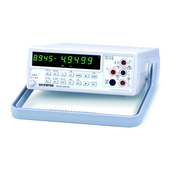
Introduction NTRODUCTION The GDM-8245 is a portable, dual-display digital multimeter suitable for a wide range of applications, such as production testing, research, and field verification. Features High DCV accuracy: 0.03%+4 Performance High current range: 20A High Voltage range: 1000V ... -
Page 12: Specifications
GDM-8245 Service Manual Specifications The following specifications apply when the instrument is powered on for at least 30 minutes within +18°C to +28°C (64.4 to 82.4°F). Accuracy is expressed as he AC specification is based on a 50% duty ±(percentage of reading + digits), t cycle, the power cord protective grounding conductor must be connected to ground, relative humidity not exceeding 75% and a 1-year calibration cycle. -
Page 13: True Rms Ac, Ac+Dc Voltage
Introduction TRUE RMS AC, AC+DC VOLTAGE Accuracy Between 2% of range and full range. Range 20Hz- 45Hz- 1kHz- 45Hz 1kHz 2kHz 500mV 1%+15 0.5%+15 0.5%+15 1%+15 0.5%+15 0.5%+15 1%+15 0.5%+15 0.5%+15 500V 1%+15 0.5%+15 -------- 1000V 1%+15 0.5%+15 -------- Range 2kHz- 10kHz- 20kHz-... -
Page 14: Frequency Measurement At Acv Range
GDM-8245 Service Manual Frequency measurement at ACV range RANGE FREQUENCY INPUT LEVEL (SINE ACCURACY WAVE) 500mV 10Hz ~ 50kHz 0.05%+1 ≥120mV 50kHz ~ 150kHz ≥200mV 0.05%+1 10Hz ~ 200kHz 0.05%+1 ≥1.2V 20Hz ~ 200kHz 0.05%+1 ≥1.2V 500V 20Hz ~ 1kHz 0.05%+1... -
Page 15: Frequency Measurement At Aca Range
Introduction refrain from using the 20A terminal for more than 15 seconds when measuring high current. Crest Factor Range 3.0 at full scale. The burden voltage is the same as the DC current. When the input exceeds the full scale of the selected range, the display will indicate over-range: ―—OL—―. -
Page 16: Diode Check
GDM-8245 Service Manual 50uF 10nF 2%+4 *5nF range is affected by the impedance of the test lead. For accuracy, please measure the range directly on the input terminal. Protection 450V dc or peak ac continuous. Diode check Description Display read forward voltage of diode. -
Page 17: Input Overload Protection
Introduction Test Lead × 1 Accessories Quick Guide manual × 1 Dimension 251(W)×91(H)×291(D) mm Weight Approx. 2.6 kg Input overload protection FUNCTION RANGE MAXIMUN INPUT 5V~1000V 1000Vdc or peak AC ACV (AC+DC) 5V~1000V 1000V rms continuous & V•Hz maximum DCA,ACA(AC+DC) 500uA~2A fuse protected: T2A 250V DC,AC20A(AC+DC) -
Page 18: Front/Rear Panel
GDM-8245 Service Manual Front/Rear Panel Secondary display Primary display DC/AC input terminal (≤2A) 1200V CAT 600V CAT Main Input DC1200V AC1000V HOLD AUTO SHIFT terminal DC mV AC mV 500V MAX/MIN AUTO/MAN POWER FUSE DC 20A AC 20A AC+Hz 250V... -
Page 19: Calibration Log
Calibration Log ALIBRATION Print out these pages and record the results. Keep it with the instrument. Model name GDM-824__ Serial number ________________ Date Year___________ Month__________ Date___________ Verified by Name____________________________ Company/Contact_________________________ Environment Temperature______°C Humidity______% Operating Voltage Verification Item Min limit Result Max limit Pass/Fail TP10~ GND... - Page 20 GDM-8245 Service Manual 2V/50Hz - 4 digits ______V + 4 digits Pass Fail 20V/50Hz - 4 digits ______V + 4 digits Pass Fail 200V/50Hz - 4 digits ______V + 4 digits Pass Fail 1000V/50Hz - 4 digits ______V + 4 digits...
- Page 21 Calibration Log 20 MΩ (19 MΩ - 40 digits ______Ω + 40 digits Pass Fail Range) DCV Calibration Item Min limit Result Max limit Pass/Fail 400mV (500mV - 3 digits ______mV + 3 digits Pass Fail Range) 4V (5V Range) - 3 digits ______ V + 3 digits...
- Page 22 GDM-8245 Service Manual 2mA/70Hz - 4 digits ______ mA + 4 digits Pass Fail (5.0mA Range) 20mA/70Hz - 4 digits ______ mA + 4 digits Pass Fail (50mA Range) 200mA/70Hz - 4 digits ______ mA + 4 digits Pass Fail...
-
Page 23: Verification Log
Verification Log ERIFICATION Print out these pages and record the results. Keep it with the instrument. Model name GDM-824__ Serial number ________________ Date Year___________ Month__________ Date___________ Verified by Name____________________________ Company/Contact_________________________ Environment Temperature______°C Humidity______% Operating Voltage Verification Item Min limit Result Max limit Pass/Fail TP10~ GND... - Page 24 GDM-8245 Service Manual Short (100Ω - 2 digits ______Ω + 2 digits Pass Fail Range) Short (500Ω - 3 digits ______Ω + 3 digits Pass Fail Range) Short (5kΩ Range) - 2 digits ______Ω + 2 digits Pass Fail Short (50kΩ...
- Page 25 Verification Log Over Pass Fail Capacitance Verification (Open) Item Min limit Result Max limit Pass/Fail Open (5nF Range) - 3 digits ______nF + 3 digits Pass Fail Open (50nF - 2 digits ______ nF + 2 digits Pass Fail Range) Open (500nF - 2 digits ______ nF...
- Page 26 GDM-8245 Service Manual Short (20A Range) - 3 digits ______ A + 3 digits Pass Fail DCA Verifcation Item Min limit Result Max limit Pass/Fail 490uA (500uA - 70 digits ______uA + 70 digits Pass Fail Range) 4.9mA (5.0mA - 70 digits...
- Page 27 Verification Log 490mA/20Hz ______ mA < 378 digits Pass Fail (500mA Range) 490mA/400Hz ______ mA < 195 digits Pass Fail (500mA Range) 490mA/2kHz ______ mA < 195 digits Pass Fail (500mA Range) 1.9A/20Hz (2A ______ A < 153 digits Pass Fail Range) 1.9A/400Hz (2A...
- Page 28 GDM-8245 Service Manual < 707 digits 490mV/20kHz ______V Pass Fail (500mV Range) < 1736 digits 490mV/50kHz ______V Pass Fail (500mV Range) AC+DC Verification Item Result Max limit Pass/Fail 200mV/50kHz ______V < 721digits Pass Fail (500mV Range) ACV Verification (part II)
- Page 29 Verification Log < 182digits 490V/1kHz ______V Pass Fail (500V Range) < 80digits 1000V/40Hz ______V Pass Fail (1000V Range) < 45digits 1000V/1kHz ______V Pass Fail (1000V Range) < 66digits 800V/40Hz ______V Pass Fail (1000V Range) < 38digits 800V/1kHz ______V Pass Fail (1000V Range) There is no adjustment point for the 1kV range.
- Page 30 GDM-8245 Service Manual DCV Verification (partI) Item Min limit Result Max limit Pass/Fail -4.9V (5V Range) - 14 digits ______ V + 14 digits Pass Fail 49V (50V Range) - 14 digits ______ V + 14 digits Pass Fail -49V (50V Range) - 14 digits...
-
Page 31: Block Diagram
Block Diagram LOCK IAGRAM The block diagram below shows the GDM-8245 system block Block Diagram diagram. The system block can be divided into 3 main parts: Description power supply circuitry, digital control circuitry and analog signal processing circuitry. A detailed summary of each section follows. - Page 32 GDM-8245 Service Manual The FS9704B, a 50,000 count digital multi-function meter Overview front-end chip is the core of the GDM-8245. This versatile chip contains a high resolution sigma-delta ADC, functional network, operational amplifier, comparator, digital filter, digital control logic and an embedded microprocessor.
- Page 33 Block Diagram sets of +5Vdc regulator U101 and U104 (both are AN7805) to produce two sets of +5Vdc regulated power sources. However, these two sets of +5Vdc regulated power sources are not used as +5Vdc power sources, they are used as two sets of +1.8Vdc power sources by connecting their ground to the -3.1Vdc output of Q102.
- Page 34 GDM-8245 Service Manual Signals for the milli-volt range are fed straight into the A/D Milli-volt Attenuation converter (AX2 terminal) without attenuation, though the signal has high impedance protection provided by the resistor R314.
- Page 35 Block Diagram Both AC voltage and current input signals are amplified by AC Amplifier & AC-to-DC U403 (OP37G) which amplifies the voltage 9.25X before being Conversion sent into the rms-to dc converter. The AC input signals are converted to dc voltages for measurement.
- Page 36 GDM-8245 Service Manual When measuring resistance, the required resistance (Ω) power Ohms Conversion source is provided by the fixed voltage generator inside FS9704B. As shown below, the measuring current flows through one of the five scale resistors in RN301 to pass the unknown Rx and thus having a voltage drop Vx produced on Rx.
- Page 37 Block Diagram When measuring AC/DC current, the current needs to be Current-to- Voltage processed and handled as a voltage. That’s why we need shunt Conversion resistors to do the conversion. When current flows through a shunt resistor, a voltage drop presents on the shunt and the current value can be calculated by having the voltage drop across the shunt divided by the resistance of that shunt resistor.
- Page 38 GDM-8245 Service Manual...
-
Page 39: Trouble Shooting
Trouble Shooting ROUBLE HOOTING Use the trouble shooting chapter to diagnose common problems for servicing. Each trouble shooting section will describe the proper working condition for each of the major components. Power-On Test ................. 40 Power Supply Checks ............... 40 Display Board Checks ............... -
Page 40: Power-On Test
GDM-8245 Service Manual Power-On Test When switched on, the GDM-8245 will beep and then perform a display test by lighting up every LED on the front panel for around two seconds. By observing this power-on test, service personnel can easily tell if there is any display defect or problems in the power-on process. -
Page 41: Display Board Checks
Trouble Shooting Display Board Checks If the display is blacked out after pressing the power button, it indicates a problem either on the display board or the power supply circuitry. Please refer to the Digital control circuitry in the digital control logic section, power supply circuitry section and use flow chart 1 and Table 2 listed below for the troubleshooting. -
Page 42: Digital Circuitry Checks
GDM-8245 Service Manual U602’s clock Pulse train of about On J601, pin 12 to pin 16 268Hz can be measured Digital Circuitry Checks Digital control related problems can be checked out by using table 3 listed below. Besides, service personnel can refer to the digital control logic section in ―Theory of... -
Page 43: Key Matrix Checks
Trouble Shooting U202, pin 16 Pulse stream of Keep pushing down one of around 53Hz Ω, CAPACITOR, AUTO/MAN buttons U202, pin 17 Pulse stream of Keep pushing down one of around 53Hz DCA, CONTINUITY or HOLD buttons U202, pin 21 ~ 28 Negative or positive Control bits going to and pulse stream of coming from the front panel... - Page 44 GDM-8245 Service Manual Table 5 ACV Signal Switching Range Component 500.00mV 5.0000V 50.000V 500.00V 1000.0V K301 K302 K303 K304 K305 K307~K310 RN301 P3 1.11MΩ SELECTED RN301 P4 101KΩ SELECTED RN301 P5 10KΩ SELECTED RN301 P6 1KΩ SELECTED R314 130KΩ SELECTED Table 5 shows which relay is actuated and which voltage-dividing resistor is selected for a given ACV measurement range.
- Page 45 Trouble Shooting Table 7 2-Wire Ω Signal Switching Range Component 500Ω 5kΩ 50kΩ 500kΩ 5MΩ 20MΩ K301 K302 K303 K304 K305~K310 RN301 P2 10MΩ USED USED RN301 P3 1.11MΩ RN301 P4 101KΩ USED RN301 P5 10KΩ USED RN301 P6 1KΩ USED USED R324 1MΩ...
- Page 46 GDM-8245 Service Manual R308 0.1Ω Shunt Selected Selected Selected Selected Selected 20A 0.01Ω Shunt Selected Table 9 shows which relay is actuated and which shunt resistor is selected for a given DCA measurement range. Table 10 ACA Signal Switching Range...
- Page 47 Trouble Shooting Table 12 ACV+Hz Signal Switching Range Component 500mV 500V K301 K302 K303 K304 K305 K307~K310 Table 12 shows which relay is actuated for a given ACV+Hz measurement range. Table 13 ACA+Hz Signal Switching Range Component 500uA 50mA 500mA K301~K305 K307 K308...
- Page 48 GDM-8245 Service Manual...
-
Page 49: Calibration
Calibration ALIBRATION The Calibration chapter describes how to make sure the instrument is operating properly by calibrating and adjusting its major functions. Please use the Calibration chapter in conjunction with the Calibration log on page 19. The Calibration log can be printed out. After calibration is complete, verification of the specifications should be performed, page 67. -
Page 50: Preparation
GDM-8245 Service Manual Preparation Servicing should only be performed by a qualified Safety technician. Before performing calibration, read the Requirements Precautions Before Use section. Failure WARNING to do so may damage the instrument or result in injury or death. In order to ensure performance accuracy, we recommend... -
Page 51: List Of Equipment
Calibration Calibration and Location: Indoor, no direct sunlight, dust free Verification Relative Humidity: 70% Environment Temperature: +18°C~+28°C Warm-up time: ≥ 30 minutes Calibration 1. Calibrate an item and record the result into the log procedure (page19). 2. -
Page 52: Component Position (Servicing)
GDM-8245 Service Manual Component Position (Servicing) U102 VC305 U105 TP12 TP10 TP15 TP11 TP14 VC303 U104 TP13 VC302 VC301 For the location of other components not related to verification and adjustment, please see the circuit diagram on page 93. -
Page 53: Entering The Calibration Mode
Calibration Entering the Calibration mode Background When asked to enter a calibration mode on the GDM-8245, please follow the procedure below. There are a number of calibration modes shown in the table below. Mode Description Calibration Modes CL10 ACV – short calibration CL20 DCV/ACA/DCA/Ω... -
Page 54: Voltage Verification
GDM-8245 Service Manual Voltage Verification Accepted range +15V±0.5V, -15V±0.5V, +3.1V±0.2V, -3.1V±0.2V, +1.8V±0.2V, +6.2V±0.2V Equipment Test leads GDM-8245 GDM-8245 Configurations TP10 TP11 +15V -15V GDM-8245 GDM-8245 TP12 TP13 +3.1V -3.1V GDM-8245 GDM-8245 TP14 TP15 +1.8V +6.2V Verification Remove the top case. Page 86. Remove the RF shield on procedure the main board. -
Page 55: Led Verification
Calibration Test points 10~15 TP10 TP12 TP11 TP10 TP12, TP10 TP11 TP10 TP14 TP13 TP15 TP13, TP14 TP15 Voltage verification is complete LED Verification Accepted range Visual inspection Equipment Verification Visually inspect that all LED indicators turn on briefly procedure when the instrument is turned on. -
Page 56: Acv, Aca, Dca, Ω Short Calibration
Accepted range < 3 digits (all ranges) Equipment Test leads Configurations GDM-8245: 500mV, 5V, 50V, 500V, 1000V Verification 1. Enter CL10 calibration mode (ACV short). procedure 2. Short the V and COM input terminals. 3. Press the Auto/Man key. The secondary display will show CL11. - Page 57 Calibration The following service procedure involves the use of high Caution voltages. Ensure proper precautions and correct safety measures are adhered to. Verification 1. Enter CL50 Calibration mode. procedure 2. Set the DMM mode to AC mV. Press Shift + ACV. 3.
-
Page 58: Frequency Response Adjustment
GDM-8245 Service Manual 1000V@50Hz 1000V±4 digits Note The Up and Down arrow keys can be used to change the DMM range up and down. Calibrating the frequency response is complete. Frequency Response Adjustment Accepted range ±10 digits (all ranges excluding 1kV) - Page 59 15. Input 1kV/1kHz. 16. Check the DMM display. Range: 1kV±20 digits Note There is no adjustment procedure for the GDM-8245 for the 1kV range. If the voltage is not within specification at 1kHz, a lower frequency (50Hz) can be used to downward calibrate the DMM. After the downward calibration, the 1kHz frequency can then be tested again.
-
Page 60: Capacitance Calibration (Open)
Configurations Resistance Calibrator: 400Ω, 4kΩ, 40kΩ, 400kΩ, 3MΩ, 9.907MΩ, 19MΩ GDM-8245 Range: 500Ω, 5kΩ, 50kΩ, 500kΩ, 5MΩ, 20MΩ Verification 1. Enter CL50 Calibration mode. procedure 2. Press Ω key to enter Resistance mode. (Range: 500 Ω) 3. -
Page 61: Dcv Calibration
DMM resistance range up and down. Resistance calibration is completed. DCV Calibration Accepted range ± 3 digits (all ranges) Equipment Multimeter calibrator Test leads Configurations GDM-8245: 500mV, 5V, 50V, 500V, 1000V Calibrator: 400mV, 4V, 40V, 400V, 1000V ... - Page 62 GDM-8245 Service Manual Verification 1. Enter CL50 Calibration mode. procedure 2. Set the mode to DC mV mode. Press SHIFT + DCV. 3. Input 400mV. 4. Check the DMM display. If the voltage is within specification, go to the next calibration range.
-
Page 63: Diode Calibration
Multimeter calibrator Test leads Configurations Calibrator: 0.537V, 0.937V GDM-8245 Range: Diode mode Verification 1. Enter CL50 Calibration mode. procedure 2. Set the mode to Diode. Press SHIFT + 3. Input 0.537V. 4. Check the DMM display. If the voltage is within the reading range, go to the next calibration range. -
Page 64: Dca Calibration
DCA Calibration Accepted range 0±3 digits (all ranges) Equipment Multimeter calibrator Test leads Configurations GDM-8245: 500uA, 5.0mA, 50mA, 500mA, 2A, 20A Calibrator: 400uA, 4.0mA, 40mA, 400mA, 2A, 8A ≤2A <20A Verification 1. Enter CL50 Calibration mode. procedure... -
Page 65: Aca Calibration
Accepted range ± 4 digits (all ranges) Equipment Multimeter calibrator Test leads Configurations GDM-8245: 500uA, 5.0mA, 50mA, 500mA, 2A, 20A Calibrator: 200uA/70Hz, 2.0mA/70Hz, 20mA/70Hz, 200mA/70Hz, 2A/50Hz, 8A (Display 8.010A)/400Hz ≤2A <20A Verification 1. Enter CL50 Calibration mode. -
Page 66: Capacitance Calibration
Accepted range ±3 digits for all ranges Equipment Capacitor calibrator Test leads Configurations GDM-8245: 5nF, 50nF, 500nF, 5uF, 50uF Multimeter Calibrator: 30nF, 300nF, 3uF, 30uF Standard capacitance: 3.282nF Verification 1. Enter CL50 Calibration mode. procedure... -
Page 67: Exit Calibration Mode
Calibration 2. Set the DMM to mode. Press . Ensure the range is set to 5nF. 3. Input 3.282nF capacitance. 4. Check the DMM display. If the capacitance is within specification, go to the next calibration range. Range: 3.282nF±3 digits 5. -
Page 68: Verification
GDM-8245 Service Manual ERIFICATION The Verification chapter describes how to make sure the instrument is operating properly by verifying its major functions after calibration. Verification is intended as a full performance inspection. Please use the Verification chapter in conjunction with the Verification log on page 23. The verification log can be printed out. -
Page 69: Resistance Verification (Short)
Accepted range Shorting (500Ω range ±3 digits, other ranges ±2 digits) Equipment Test leads Configurations GDM-8245 Range: 500Ω, 5kΩ, 50kΩ, 500kΩ, 5MΩ, 20MΩ Verification 1. Set the GDM-8245 range to 500Ω. procedure 2. Short the test leads. Verify the resistance as 0±3 digits. -
Page 70: Diode Verification
3. Reverse the polarity of the connection. OL (overload) should be displayed on the DMM. Diode verification is complete. Capacitance Verification (Open) Accepted range ±3 digits for 5nf range; ±2 digits for all other ranges Equipment Configurations GDM-8245: 5nF, 50nF, 500nF, 5uF, 50uF ... -
Page 71: Capacitance Verification
1.006nF±28. 2. Repeat the procedure for the rest of the ranges. Capacitance verification is complete DCA Verification (Short) Accepted range ±3 digits all ranges Equipment Test leads Configurations GDM-8245 range: 500uA, 5.0mA, 50mA, 500mA, 2A, ... -
Page 72: Dca Verification
1.9A±41, 19A*±41 Equipment Multimeter calibrator Test leads Configurations GDM-8245: 500uA, 5.0mA, 50mA, 500mA, 2A, 20A Calibrator: 490uA, 4.9mA, 49mA, 490mA,1.9A, 19A* <2A <20A* *Do not input 19A for more than 1 second. Exceeding 1 second may blow the fuse. -
Page 73: Aca Verification
4.9mA/20Hz/2kHz/20kHz, 49mA/20Hz/2kHz/20kHz, 490mA/20Hz/400Hz/2kHz, 1.9A/20Hz/400Hz/2kHz, 19A* /20Hz/400Hz/2kHz <2A <20A* *Do not input 19A for more than 1 second. Exceeding 1 second may blow the fuse. Calibration 1. Set the range to 500uA (ACA) on the GDM-8245. procedure 2. Input 490uA/20Hz. Verify 490uA(20Hz)<378... -
Page 74: Acv Verification (Short)
ACV Verification (Part 1) Accepted range (Digits): 490mV(20Hz)<353; 490mV(2kHz)<182; 490mV(10kHz)<353; 490mV(20kHz)<707; 490mV(50kHz)<1736 Equipment Multimeter calibrator Test leads Configurations GDM-8245: 500mV Calibrator: 490mV/20Hz/2kHz/10kHz/20kHz/50kHz Verification 1. Set the range to 500mV (GDM-8245). procedure 2. Input 490mV/20Hz. Verify the results. -
Page 75: Ac+Dc Verification
Accepted range (Digits): 4.9V(20Hz)<353; 4.9V(2kHz)<182; 4.9V(10kHz)<353; 4.9V(20kHz)<707; 4.9V(50kHz)<1736 49V(20Hz)<353; 49V(2kHz)<182; 49V(10kHz)<353; 49V(20kHz)<707; 49V(50kHz)<1736 490V(40Hz)<353; 490V(1kHz)<182 1000V(40Hz)<80; 1000V(1kHz)<45 800V(40Hz)<66; 800V(1kHz)<38 Equipment Multimeter calibrator Test leads Configurations GDM-8245: 5V, 50V, 500V, 1000V Calibrator: 4.9V/20Hz/2kHz/10kHz/20kHz/50kHz, 49V/20Hz/2kHz/10kHz/20kHz/50kHz, 490V/40Hz/1kHz, 1000V/40Hz/1kHz, 800V/40Hz/1kHz... -
Page 76: Dcv Verification (Short)
GDM-8245 Service Manual Verification 1. Set the range to 5V (GDM-8245). procedure 2. Input 4.9V/20Hz. Verify the results. 3. Repeat for the remaining ranges and frequencies. Note There is no adjustment point for the 1kV range. However, the 1kV/50Hz range can be downward calibrated. -
Page 77: Dcv Verification (Dbm)
(Digits): 16.02 dBm ± 3 Equipment Multimeter calibrator Test leads Configurations GDM-8245: 5V (DCV → dBm) Calibrator: 4.9V DC Verification 1. Set the range to 5V (DCV). procedure 2. Input 4.9V DC. Press the dBM button. Verify the results. -
Page 78: Beeper Test
3. Set the calibrator to 7Ω. Verify the beeper does not sound. Beeper verification is complete Frequency Measurement Verification Accepted range 200kHz ±2digits at 1.1V. Equipment Multimeter calibrator Test leads Configurations GDM-8245 range: AC+Hz mode Calibrator: 1.1V/200kHz ... - Page 79 Verification Verification 1. Set the mode to ACV, 5V range. procedure 2. Set the mode to AC+Hz. 3. Input 1.1V/200kHz. Verify the results. Note The primary display will not show a voltage reading with a frequency of 200kHz Frequency Measurement Verification is complete...
-
Page 80: Changing The Ac Mains / Fuse
GDM-8245 Service Manual AC M HANGING THE AINS Before replacing the fuse, make sure the cause of fuse Changing the Fuse blowout has been fixed. Before replacing the fuse, ensure the power cord has been disconnected from mains power. WARNING Failure to do so may result in injury or death. - Page 81 Changing the AC Mains / Fuse Ensure the correct line voltage is lined up with the arrow on the fuse holder. Insert the fuse socket. 100V/120V T0.1A 250V Rating 230V T0.08A 250V...
-
Page 82: Replace Input Current Fuse
GDM-8245 Service Manual Replace the Input Current Fuse Step Press the fuse holder with a flat screwdriver. Turn anticlockwise. Remove the fuse assembly. Replace the fuse at the end of the holder. Rating T2A, 250V... -
Page 83: Replaceable Parts And Disassembly
ARTS AND ISASSEMBLY The Replacement Parts and Disassembly chapter lists the replaceable mechanical components of the GDM-8245 and shows how to remove the PCBs, panels, and outer casing from the instrument. The procedures described in this chapter are intended for parts replacement and board adjustment. -
Page 84: External View
GDM-8245 Service Manual External View Handle Front panel Top case Bottom case Rear panel... -
Page 85: Disassembly
Replaceable Parts and Disassembly Disassembly Disassembly Equipment Here is the list of all equipment used during disassembly. Item Requirements Used in Phillips Various sizes Adjustments screwdriver Disassembly Flathead screwdriver... -
Page 86: Outer Casing
GDM-8245 Service Manual Outer Casing 1. Pull the handle base out slightly 4. Remove the handle fixtures from the case insert. 2. Turn the handle until it is in the upright position. 3. Pull the handle bases out from DMM case. -
Page 87: Main Pcb And Front/Rear/Bottom Panel Removal
Replaceable Parts and Disassembly Main PCB and Front/Rear/Bottom Panel Removal 1. Remove the outer casing. Page 86 3. Remove the terminal connector the ribbon cable coming from the front 2. Remove the 5 screws holding the panel PCBs. main PCB to the bottom case. 5. -
Page 88: Front Panel Pcb Removal
GDM-8245 Service Manual Front Panel PCB Removal. 1. Remove the front panel from the 3. Remove the PCB to reveal the LEDs bottom case and main PCB. Page 87 and key matrix. 2. Remove the 4 screws from the front panel PCB. -
Page 89: Gdm-8245 Mechanical Parts List
4260-20D08501 BINDING POST DM01M07A ,1P ,0 (Black terminal) 44BJ-011005A BINDING POST DM01M07A ,1P ,2 (Red terminal) 44BJ-211004A 51DM-824501D1 NP GDM-8245 MAIN NP (新 LOGO) ,RoHS SILICON RUBBER GDM-8245/8246 ,GRAY ,RoHS 57RB-40G036A1 PC GDM-8245/6 TERMINAL HOLDER 63PH-AG1003B1 PLATE,ABS,GRAY,RoH FUSE HOLDER R3-11 ,5*20m/m ,RoHS... -
Page 90: Top And Bottom Case
GDM-8245 Service Manual Top and Bottom Case Qty. Description Part number PC TOP COVER ,GRAY 63UP-AG1062B RUBBER FOOT TF-419NP(G) ,21.8*15.8*5.5 ,RoHS 57FC-40G001B1 PC SFG-1003/1013 BOTTOM COVER ,GRAY ,RoHS 63LO-AG102001 CA FRP-375P80-02T, RoHS 62DS-830PP101 AL PAPER FG02M190 ,207*196*0.1T 6861-2071960 PC HANDLE ,GRAY ,RoHS 63HD-AG1010B1 WASHER "C TYPE"... -
Page 91: Rear Panel And Handle
Screw with washer SCREW BMS 3*6 ,ISO ,N (WASHER P ,S) 594B-W3006NS Washer CA FG02M15A ,SCREW HOLDER PLATE 62FG-215HP1A Mainboard PCB (plain) PCB DM01P01D ,2 ,FR4 ,GDM-8245 35DM-01P010D Front panel PCB PCB DM01P02D ,2 ,FR4 (2 IN ONE 35DM-01P020D PCS) ,GDM-8245... -
Page 92: Circuit Diagrams And Component Parts List
After problematic locations are discovered, the Components Parts List may be used for securing replacement parts. Circuit Diagram 1 (GDM-8245) ..........93 Circuit Diagram 2 (GDM-8245) ..........94 Circuit Diagram 3 (GDM-8245) ..........95 Circuit Layout (GDM-8245) ............96... -
Page 93: Circuit Diagram 1 (Gdm-8245)
Circuit Diagrams and Component Parts List Circuit Diagram 1 (GDM-8245) -
Page 94: Circuit Diagram 2 (Gdm-8245)
GDM-8245 Service Manual Circuit Diagram 2 (GDM-8245) -
Page 95: Circuit Diagram 3 (Gdm-8245)
Circuit Diagrams and Component Parts List Circuit Diagram 3 (GDM-8245) -
Page 96: Circuit Layout (Gdm-8245)
GDM-8245 Service Manual Circuit Layout (GDM-8245) -
Page 97: Gdm-8245 Component Parts List
Circuit Diagrams and Component Parts List GDM-8245 Component Parts List Part ID Description Part number F301, FUSE T 5.0*20 2A 250V UL/CSA GMC-2A 37FT-1114202 AC230V, FUSE T 5*20 0.08A 250V, 218XP, RoHS 37FT-11648001 J301, VH00-32#22-100mm-2BB310-2, 40WCJ30600301 JFE-9512013-2, RoHS PILLAR HEXAGON ,M3*20m/m ,N ,RoHS... - Page 98 (AD536AJD ,AD536AKH ,ANDE),RoHS X201, CRYSTAL 4.000MHz HC-49/U 2800-04M0007 (H49-4.0000-20) L101, COIL 1.6mH ,5A Q>=2.2 18T 2900-162502A 0.75@ ,APS-10452 (CE) T101, TS GDM-8245-PT ,PCB ,HP-057190697 3000-DM01600 100/120/230V K308,K307, RELAY OEG 3312-05P0010 OUAZ-SS-105L ,DC5V ,40mA ,PCB ,SPDT K301,K302, RELAY 3322-0502050 DS2E-SNil-DC5V-R ,DC5V ,2A ,DPDT BZ301, PIEZO BUZZER 2.5kHz 30m/m...
- Page 99 22C1-1A431J01 C307,C331, CSI 500V ,8PD ,CD15CD080D03F ,RoHS 22C1-5A080D01 F101, FUSE T 8.35*7.7 0.5A 250V U/C/V/S 37FT-77945011 MRT-0.5 ,bel U202, *IC W78E054C-40DL ,GDM-8245 V2.00 2799-04600601 (1AD065) W/LB RN301, RN 10M+/-0.25%,15P(2-7,9,11 2062-SORT010 X)(SORTING,GDM-8245) R321, RM 1/2WS ,10kF ,T52 ,MF1/2WS1% ,RoHS 2013-1002FH01 U102,...
- Page 100 GDM-8245 Service Manual C108,C117, CSE1 35V 2200uM 16@*25 F=7.5 2241-35228M11 SKR222M1VK25H RoHS C604,C602,C603, CSL 50V ,0.1uZ ,Y5V ,0603 ,RoHS 22EJ-50104Z01 R625,R621,R622,R624,R627, R CHIP 1/10W ,68.1RF ,RC0603 ,RoHS 20C0-681DF211 R628,R623,R626, R611,R612,R613,R614,R615, R CHIP 1/10W ,82.5RF ,RC0603 ,RoHS 20C0-825DF211 R616,R617,R618, D631,D632,D629,D630, DIODE RLS4148TE-11 ,SMD...
Need help?
Do you have a question about the GDM-8245 and is the answer not in the manual?
Questions and answers