GW Instek GDM-8200A Series User Manual
Gdm-8200a series digital multimeter
Hide thumbs
Also See for GDM-8200A Series:
- User manual (122 pages) ,
- Quick user manual (7 pages) ,
- User manual (122 pages)
Table of Contents
Advertisement
Quick Links
Download this manual
See also:
User Manual
• FAST SHIPPING AND
DELIVERY
• TENS OF THOUSANDS OF
IN-STOCK ITEMS
• EQUIPMENT DEMOS
• HUNDREDS OF
MANUFACTURERS
SUPPORTED
• LEASING/MONTHLY
RENTALS
• ITAR CERTIFIED
SECURE ASSET SOLUTIONS
Artisan Technology Group
new and certified-used/pre-owned equipment
SERVICE CENTER REPAIRS
Experienced engineers and technicians on staff
at our full-service, in-house repair center
View
Instra
REMOTE INSPECTION
SM
Remotely inspect equipment before purchasing with
www.instraview.com
our interactive website at
Contact us:
(888) 88-SOURCE | sales@artisantg.com | www.artisantg.com
is your source for quality
WE BUY USED EQUIPMENT
Sell your excess, underutilized, and idle used equipment
We also offer credit for buy-backs and trade-ins
www.artisantg.com/WeBuyEquipment
LOOKING FOR MORE INFORMATION?
Visit us on the web at
information on price quotations, drivers, technical
specifications, manuals, and documentation
www.artisantg.com
for more
Advertisement
Chapters
Table of Contents

Related Manuals for GW Instek GDM-8200A Series


Summary of Contents for GW Instek GDM-8200A Series
- Page 1 Artisan Technology Group is your source for quality new and certified-used/pre-owned equipment SERVICE CENTER REPAIRS WE BUY USED EQUIPMENT • FAST SHIPPING AND DELIVERY Experienced engineers and technicians on staff Sell your excess, underutilized, and idle used equipment at our full-service, in-house repair center We also offer credit for buy-backs and trade-ins •...
-
Page 2: Digital Multimeter
Digital Multimeter GDM-8200A Series USER MANUAL GW INSTEK PART NO. 27A1-8255A10 This manual contains proprietary information, which is protected by copyrights. All rights are reserved. No part of this manual may be photocopied, reproduced or translated to another language without prior written consent of Good Will company. -
Page 3: Table Of Contents
Safety Guidelines..........6 SCANNER (OPTIONAL) ..........68 GETTING STARTED ............9 GDM-SC1 Scanner Specifications ....69 Scanner Installation......... 69 GDM-8200A Series Lineup ....... 10 Setup Scan ............76 GDM-8200A Series Characteristics ....11 Run Scan ............82 Front Panel Overview........12 Rear Panel Overview ........ -
Page 4: Safety Instructions
Caution: Identifies conditions or practices that could Measurement category I is for measurements performed on circuits • result in damage to the GDM-8200A series or to other not directly connected to Mains. CAUTION properties. - Page 5 Make sure the correct type of fuse is installed before • power up. WARNING When using the GDM-8200A series in the United Kingdom, make sure the To ensure fire protection, replace the fuse only with • power cord meets the following safety instructions.
-
Page 6: Getting Started
GDM-8200A series consists of two models: GDM-8251A and GDM-8255A. Both two models are identical except for the model name and Appearance This chapter describes the GDM-8200A series in a the meter count of the 1 display. nutshell, including its main features, package contents, and front / rear / display panel introduction. -
Page 7: Gdm-8200A Series Characteristics
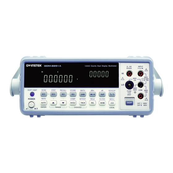
GETTING STARTED GDM-8200A Series User Manual GDM-8200A Series Characteristics Front Panel Overview The GDM-8200A series are portable, dual-display digital Main Measurement 4W Ohm Fuse Display Terminal multimeters suitable for wide range of applications, such as production testing, research, and field verification. -
Page 8: Measurement Keys (Upper Row)
GETTING STARTED GDM-8200A Series User Manual Accepts ground (COM) line in all Starts the step measurement (page76) COM Terminal SHIFT → DCV measurements except the sense line in using the optional scanner. (STEP) 4W Resistance (page30). When the ACV key and the DCV key... -
Page 9: Measurement Keys (Lower Row)
GETTING STARTED GDM-8200A Series User Manual Measures Temperature (page37). Measures the Maximum or the °C/°F MX/MN Minimum value (page45). (Temperature) (MAX/ MIN) Selects the type of thermocouple Selects the digital filter type for the SHIFT + °C/°F SHIFT → used in the Temperature signal sampling (page62). -
Page 10: Rear Panel Overview
GETTING STARTED GDM-8200A Series User Manual Accepts a digital I/O cable for the Digital I/O port Rear Panel Overview Hi/Lo limit test; DB-9 pin, female connector. Optional Item Power Cord For digital I/O details, see page86. Slot x2 Socket Accepts up to two optional scanner modules. 16 Optional slot x2 channels are available per scanner. -
Page 11: Set Up
GETTING STARTED GDM-8200A Series User Manual Power Up Set Up 1. Connect the power Power up steps cord to the AC Tilt Stand Voltage input. Pull out the Tilt stand steps handle sideways and rotate it. Make sure the ground connector of the power cord is connected to a safety ground. -
Page 12: Basic Measurement
BASIC MEASUREMENT GDM-8200A Series User Manual Basic Measurement Overview ASIC MEASUREMENT Basic measurement refers to the eight types of Background measurements assigned to the upper row keys on the front panel. AC Voltage Measurement type ACV DC Voltage AC+DC Voltage... -
Page 13: Ac/Dc/Ac+Dc Voltage Measurement
DCV (DC Voltage) key. Common attribute: manual/automatic triggering For AC+DC Voltage, press the ACV key and the DCV key together. The GDM-8200A series triggers according to the refresh Automatic rate. See the previous page for refresh rate setting details. triggering 2. -
Page 14: Select Voltage Range
BASIC MEASUREMENT GDM-8200A Series User Manual Select Voltage range Voltage conversion table This table shows the relationship between AC, DC, and AC+DC reading in To turn the automatic range selection Auto range various waveforms. On/Off, press the AUTO key. Waveform... -
Page 15: Ac/Dc/Ac+Dc Current Measurement
BASIC MEASUREMENT GDM-8200A Series User Manual Crest factor table AC/DC/AC+DC Current Measurement Crest factor is the ratio of the peak signal amplitude to the Background RMS value of the signal. It determines the accuracy of AC 0 ~ 10A Current type measurement. -
Page 16: 2W/4W Resistance Measurement
BASIC MEASUREMENT GDM-8200A Series User Manual Select Current range 2W/4W Resistance Measurement To turn the automatic range selection Auto range On/Off, press the AUTO key. Uses the standard V-COM ports. Measurement 2-wire Recommended for measuring resistances type Press the Up or the Down key to select Manual range larger than 1kΩ. -
Page 17: Diode Test
BASIC MEASUREMENT GDM-8200A Series User Manual Select Resistance range Diode Test To turn the automatic range selection Auto range On/Off, press the AUTO key. Diode test checks the forward bias characteristics of a Background diode by running a constant forward bias current, approx. -
Page 18: Continuity Test
BASIC MEASUREMENT GDM-8200A Series User Manual Set continuity threshold Continuity Test Continuity threshold defines the maximum resistance Background allowed in the DUT when testing the continuity. Continuity test checks that the resistance in the DUT is Background low enough to be considered continuous (of conductive 0 ~ 1000Ω, 1Ω... -
Page 19: Frequency/Period Measurement
BASIC MEASUREMENT GDM-8200A Series User Manual Select beeper setting Frequency/Period Measurement Beeper setting defines how the GDM-8200A series Background notifies the continuity test result to the user. To measure Frequency, press the 1. Activate Hz/P key once. frequency/period Beeps when the test result is pass... -
Page 20: Temperature Measurement
BASIC MEASUREMENT GDM-8200A Series User Manual Select thermocouple type Temperature Measurement The GDM-8200A series assumes that a certain type of Background thermocouple, which reads voltage fluctuation induced the GDM-8200A series accepts thermocouple input and Background by temperature changes, is used to measure the calculates the temperature from the voltage fluctuation. -
Page 21: Set Reference Junction Temperature
When a thermocouple is connected to the GDM-8200A Background DVANCED series, the temperature difference between the thermocouple lead and the the GDM-8200A series input terminal should be taken into account and be cancelled; MEASUREMENT otherwise an erroneous temperature might be added. -
Page 22: Advanced Measurement
When there is no captured data, the reading indicator When no data is AC/DCV AC/DCI 2/4W Hz/P °C/°F flashes once per two seconds (slower than the normal captured refresh rate), showing the GDM-8200A series is in the ● — — — — — waiting mode. -
Page 23: Dbm/Db Measurement
(NOT applicable to ACV+DCV) Measure dB Using the ACV or DCV measurement result, the Background GDM-8200A series calculates the dB or dBm value based dB is defined as [dBm−dBmref]. When the dB Background on a reference resistance value in the following way. -
Page 24: Max/Min Measurement
ADVANCED MEASUREMENT GDM-8200A Series User Manual Max/Min Measurement Relative Value Measurement Applicable to Applicable to Maximum and Minimum measurement stores the highest Relative measurement stores a value, typically the data at Background Background (maximum) or lowest (minimum) reading and shows it on the moment, as the reference. -
Page 25: Hold Measurement
ADVANCED MEASUREMENT GDM-8200A Series User Manual 3. Press the Enter key to confirm Hold Measurement the value, or the Exit key to cancel. The display switches to (confirm) measurement. Applicable to (cancel) To cancel the Relative measurement, Hold measurement retains the current measurement data... -
Page 26: Compare Measurement
ADVANCED MEASUREMENT GDM-8200A Series User Manual Compare Measurement 3. Low limit setting Applicable to Compare measurement checks and updates if the Background Shows the low limit value 1st display measurement data stays between the upper (high) and Indicates low limit setting 2nd display lower (low) limit specified. -
Page 27: Math Measurement
ADVANCED MEASUREMENT GDM-8200A Series User Manual Math Measurement If the 2 display 5. Result High shows High, the result is above the High Applicable to limit. Math measurement runs three types of mathematical Digital I/O: FAIL Out (Pin 6) and HIGH... -
Page 28: Measure 1/X
ADVANCED MEASUREMENT GDM-8200A Series User Manual 2. Change the parameter using the Measure 1/X Up/Down key. 3. Press the ENTER key to Press the Shift key, the 2/4W (Math) 1. Activate 1/X confirm editing and move to key, the Down key twice. The 1/X offset setting. -
Page 29: Dual Display Measurement
ADVANCED MEASUREMENT GDM-8200A Series User Manual ● ● ● ● ● 2W* (see Note) 1. Use the Left/Right key to move the cursor (flashing point) ● ● ● ● ● Hz/P between high/low setting, digits, — — — — —... -
Page 30: System/Display Configuration
SYSTEM/DISPLAY CONFIGURATION GDM-8200A Series User Manual Refresh Rate Setting YSTEM/ ISPLAY Refresh rate defines how frequently the GDM-8200A Background series captures and updates the measurement data. Faster refresh rate yields lower accuracy and resolution. Slower CONFIGURATION refresh rate yields higher accuracy and resolution. -
Page 31: Trigger Setting
Trigger Setting TRIG key. The EXT indicator external trigger appears on the display. Manual/Automatic triggering the GDM-8200A series triggers according to the refresh Automatic rate. See the previous page for refresh rate setting details. triggering Press the TRIG key to start 2. -
Page 32: Digital Filter Setting
Overview 3. Move the flashing point (cursor) using the Left/Right key. Change the value using the The the GDM-8200A series internal digital filter converts Filter basic Up/Down key. the analog input signal into digital format before passing it to internal circuits for processing. The filter affects the 4. -
Page 33: Display Setting
SYSTEM/DISPLAY CONFIGURATION GDM-8200A Series User Manual Filter setting Display Setting 1. Press the Shift key followed by Step the MX/MN (Filter) key. Display light setting Display light setting adjusts the brightness of the display Background reading. Use level 3 or more (brighter) when working indoor;... -
Page 34: Store/Recall
Store Measurement Record ........66 Result Recall Measurement Record ........67 Store Measurement Record the GDM-8200A series can store the measurement Background history which can be recalled later for observation and analysis as in Maximum, Minimum, and Average value. 1 ~ 9999... -
Page 35: Recall Measurement Record
Recall Measurement Record The optional scanner GDM-SC1 lets you effectively measure multiple channels connected to a single the GDM-8200A series. The GDM-8200A series can recall the stored Background measurement history for observation and analysis as in Maximum, Minimum, and Average value. -
Page 36: Gdm-Sc1 Scanner Specifications
SCANNER (OPTIONAL) GDM-8200A Series User Manual GDM-SC1 Scanner Specifications 3. The connection terminals appear. 16 pairs 2A (ch17, ch18) 2-wire channel Maximum current 8 pairs 2/4 wire 4-wire channel Resistance N/A (internal) Single wire channel Cold junction 300V Screw terminal... -
Page 37: Select Channel Group And Enable Scanner
SCANNER (OPTIONAL) GDM-8200A Series User Manual Select Channel group and enable scanner Connect wire 2 groups, 16 channels each, are available for the scanner. Make sure the wires have at least the same Voltage and Background Wire selection Current capacity as the maximum ratings in the... -
Page 38: Insert Scanner
Close the cover by tightening the screws. Print out the configuration record list on page75, fill in Configuration the details, and keep it with the GDM-8200A series. Record Insert scanner Turn the Power Off and take off the power cord. -
Page 39: Setup Scan
(Continuous) CH10 of loop count. Then it goes into the idle mode. CH11 the GDM-8200A series stays in the idle External CH12 mode by default. The trigger timing is (Manual) manually controlled by the user from the CH13 front panel (TRIG key). -
Page 40: Setup Simple Scan
SCANNER (OPTIONAL) GDM-8200A Series User Manual Setup Simple Scan 1. Press the Shift key, the 2 Panel operation (MENU), the Left key. The Scan 6. Move the cursor to the channel menu appears. using the Left/Right key, and change the value using the Up/Down key. -
Page 41: Setup Advanced Scan
SCANNER (OPTIONAL) GDM-8200A Series User Manual Setup Advanced Scan 1. Press the Shift key, the 2 Panel operation (MENU), the Left key. The Scan 1 ~ 100 Range menu appears. 6. Move the cursor to the channel using the Left/Right key, and change the value using the Up/Down key. -
Page 42: Run Scan
SCANNER (OPTIONAL) GDM-8200A Series User Manual Use external trigger Run Scan the GDM-8200A series uses the internal trigger by Background default. Using an external trigger allows customized Overview triggering. Measures all specified channel range at Scan operation Scan Connect the external trigger signal to the Digital I/O Signal each trigger event. -
Page 43: Recall Scan/Step Result
SCANNER (OPTIONAL) GDM-8200A Series User Manual Recall Scan/Step result 3. Press the Down key. The channel selection appears. 1. After the Scan/Step is Panel operation completed, the data is stored internally. Press the Shift key followed by the ACI (Recall) key. -
Page 44: Digital I/O
DIGITAL I/O GDM-8200A Series User Manual Digital I/O Terminal Configuration IGITAL I/O The digital I/O terminal outputs the result of Compare Background measurement to control external devices. By providing separate VCC for the terminal, the outputs can also be The rear panel Digital I/O terminal outputs the result of used as power source for TTL and CMOS logics. - Page 45 DIGITAL I/O GDM-8200A Series User Manual Application: Compare measurement 4. Set the low limit in the same way as in the high limit. Press the Applicable to ENTER key to confirm editing. The compare measurement Compare measurement checks and updates if the Background starts right away.
-
Page 46: Remote Control
DIGITAL I/O GDM-8200A Series User Manual Application: External trigger the GDM-8200A series uses the internal trigger by Background EMOTE CONTROL default, for example to count the frequency and the period. Using an external trigger allows customized triggering condition. Connect the external trigger signal to the Digital I/O Signal port located on the rear panel. -
Page 47: Configure Interface
REMOTE CONTROL GDM-8200A Series User Manual 5. Press the ENTER key to Configure Interface confirm USB selection. 6. Connect the USB cable to the Overview rear panel terminal (upper K E Y C A L port). USB 1.1 or 2.0, TypeA, female... -
Page 48: Command Syntax
Floating point number: 4.5e-1, 8.5e+1,... the GDM-8200A series automatically min, max translates to Minimum (min) or Maximum (max) value available. the GDM-8200A series automatically translates the Automatic command parameter into the closest available value. parameter range selection conf:volt:dc_1 (Sets the measurement Example 1 item to DC Voltage and the range to 1V). -
Page 49: Command Set
REMOTE CONTROL GDM-8200A Series User Manual conf:per Sets measurement to Period and specifies range. Command Set conf:cont Sets measurement to Continuity. conf:diod Sets measurement to Diode. Commands are non-case sensitive. • conf:temp Sets measurement to Temperature. Underline means a single space (dc_1→DC 1V). -
Page 50: Unit Command
REMOTE CONTROL GDM-8200A Series User Manual sens:aver:tcon Selects digital filter type. calc:aver:min? Returns minimum value stored. Parameter: mov (moving), rep (repeating) calc:aver:max? Returns maximum value stored. Example: sens:aver:tcon_mov (moving digital filter) calc:aver:aver? Returns average value stored. sens:aver:tcon? Returns digital filter type. -
Page 51: Trigger Command
REMOTE CONTROL GDM-8200A Series User Manual calc:math:perc Sets target value in Math measurement. trac:cle Clears buffer contents. Parameter: NR2 Example: calc:math:perc_50 (target set to 50) SYStem related command calc:hold:ref Set percentage of Hold function. Parameter: 0 to 99, min, max syst:disp Turns display On or Off. -
Page 52: Route Command
Parameter: 0 (scan off), 1 (monitor), 2 (step), 3 (scan), 4 *stb? Returns SBR (Status Byte Register) contents. (advance) Example: 81 means SBR=01010001 *trg Manually triggers the GDM-8200A series. Secondary display: CONFigure2 command ROUTe command conf2:volt:dc Configure 2 display to DC Voltage. -
Page 53: Faq
● I pressed the EXIT key but cannot get out of Scanner mode. (DCA-mA), 6 (ACA-mA), 7 (2WR), 8 (Freq), 9 (TempC), 10 (AC+DCA-10A), 11 (AC+DCV), 12 (AC+DCA-mA), 13 (Diode), ● The the GDM-8200A series performance does not match the 14 (Period), 15 (TempF), 16 (4WR), 17 (Cont.) specifications. -
Page 54: Appendix
APPENDIX GDM-8200A Series User Manual Firmware Version PPENDIX Firmware version is available for viewing system Background information. Shows the GDM-8200A series Firmware firmware version number. version System Info Firmware Version..........105 1. Press the Shift key followed by View firmware Fuse Replace AC source fuse ........107... -
Page 55: Fuse Replacement
APPENDIX GDM-8200A Series User Manual Replace input current fuse Fuse Replacement 1. Press the Fuse holder. Step Replace AC source fuse 1. Take off the power cord and remove the fuse socket Step using a minus driver. 2. Replace the fuse in the holder. -
Page 56: Specifications
APPENDIX GDM-8200A Series User Manual DC Voltage Specifications Max. Input: 1000V DC or Peak on all range • Total accuracy of (AC + DC) voltage does not exceed the • Note General sum of AC voltage accuracy and DC voltage accuracy... - Page 57 APPENDIX GDM-8200A Series User Manual 10.00V 10mV 12.00V 19.99V 100.0V 100mV 120.0V 199.9V AC Current 750V(*) 750V 750V The following ac current specifications are for sinusoidal Rate Range Accuracy (reading%+digits) • signals with amplitudes greater than 5% of its range.
- Page 58 APPENDIX GDM-8200A Series User Manual 100.000Ω 120.000Ω 199.999Ω 0.1% + 8* 10.00kΩ 12.00kΩ 19.99kΩ 0.05% + 2 1.00000kΩ 1.20000kΩ 1.99999kΩ 0.08% + 5* 100.0kΩ 120.0kΩ 199.9kΩ 0.05% + 2 10.0000kΩ 12.0000kΩ 19.9999kΩ 0.06% + 5* 1.000MΩ 1.200MΩ 1.999MΩ 0.05% + 2 100.000kΩ...
-
Page 59: Ec Declaration Of Conformity
APPENDIX GDM-8200A Series User Manual EC Declaration of Conformity NDEX GOOD WILL INSTRUMENT CO., LTD. (1) No.7-1, Jhongsing Rd., Tucheng City, Taipei County, Taiwan (2) No. 69, Lu San Road, Suzhou City (Xin Qu), Jiangsu Sheng, China display setting command set....100... -
Page 60: Index
INDEX command set ........98 scanner front panel key........14 command set........101 setting..........52 get out of scanner mode ....104 monitor channel ........83 series lineup..........10 service contact ........104 specification conditions ......104 output key faq ........104 table of contents........3 period temperature front panel key........14... - Page 61 Artisan Technology Group is your source for quality new and certified-used/pre-owned equipment SERVICE CENTER REPAIRS WE BUY USED EQUIPMENT • FAST SHIPPING AND DELIVERY Experienced engineers and technicians on staff Sell your excess, underutilized, and idle used equipment at our full-service, in-house repair center We also offer credit for buy-backs and trade-ins •...
Need help?
Do you have a question about the GDM-8200A Series and is the answer not in the manual?
Questions and answers