Sign In
Upload
Download
Table of Contents
Contents
Add to my manuals
Delete from my manuals
Share
URL of this page:
HTML Link:
Bookmark this page
Add
Manual will be automatically added to "My Manuals"
Print this page
×
Bookmark added
×
Added to my manuals
Manuals
Brands
GW Instek Manuals
Multimeter
GDM-541
User manual
GW Instek GDM-541 User Manual
Handheld digital multimeter
Hide thumbs
1
2
3
4
5
6
7
8
9
10
11
12
13
14
15
16
17
18
19
20
21
22
23
24
25
26
27
28
29
30
31
32
33
34
35
36
37
38
39
40
41
42
43
44
45
46
47
48
49
50
51
52
53
54
55
56
page
of
56
Go
/
56
Contents
Table of Contents
Bookmarks
Table of Contents
Table of Contents
Safety Instructions
Etting Started
Getting Started
Accessories
GDM-541/533 Overview
Overview
External Structure
LCD Display
Function Dial
Function Dial and Function Buttons
Function Buttons
Peration
AC Voltage Measurement
Operating Instructions
Operation
DC Voltage Measurement
AC+DC Voltage Measurement (GDM-541)
AC/DC Millivolt Voltage Measurement
Loz (Low Impedance) ACV Measurement (GDM-533)
Loz (Low Impedance) ACV Measurement (GDM-533)21
Resistance Measurement
Continuity Test
Diode Test
Capacitance Measurement
Transistor Magnification (Hfe) Measurement (GDM - 541)
Transistor Magnification (Hfe) Measurement (GDM-541)
Frequency/Duty Ratio Measurement
Temperature Measurement (GDM-533)
AC/DC Current Measurement
Non-Contact Voltage (NCV) Detection
USB Data Transmission
Others
General Specifications
Specifications
Electrical Specifications
DC Voltage
AC Voltage
AC+DC Voltage
Resistance
Continuity and Diode
Transistor Magnification (GDM-541)
Capacitance
DC Current
Temperature (GDM-533)
AC Current
Frequency/Duty Ratio
Indicator Light
General Meintenance
Maintenance
Battery/Fuse Replacement
Advertisement
Quick Links
1
Gdm-541/533 Overview
2
Transistor Magnification (Hfe) Measurement (Gdm - 541)
Download this manual
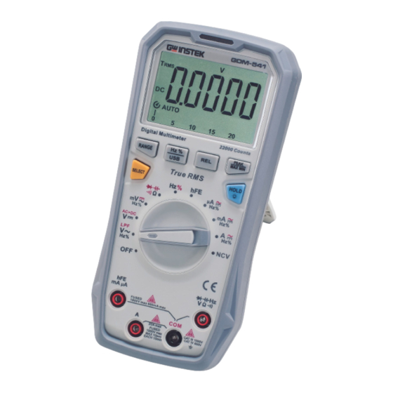
Handheld Digital Multimeter
GDM-541/533
USER MANUAL
ISO-9001 CERTIFIED MANUFACTURER
Table of
Contents
Previous
Page
Next
Page
1
2
3
4
5
Advertisement
Chapters
Table of Contents
3
Etting Started
7
Peration
14
Electrical Specifications
42
Table of Contents
Need help?
Do you have a question about the GDM-541 and is the answer not in the manual?
Ask a question
Questions and answers
Related Manuals for GW Instek GDM-541
Multimeter GW Instek GDM-532 User Manual
Handheld digital multimeter (38 pages)
Multimeter GW Instek GDM-531 User Manual
Handheld digital multimeter (32 pages)
Multimeter GW Instek GDM-533 User Manual
Handheld digital multimeter (56 pages)
Multimeter GW Instek GDM-397 User Manual
Handheld digital multimeter (64 pages)
Multimeter GW Instek GDM-8200A Series Quick User Manual
(7 pages)
Multimeter GW Instek GDM-8246 Manual
(28 pages)
Multimeter GW Instek GDM-8245 Service Manual
(100 pages)
Multimeter GW Instek GDM-8245 User Manual
(56 pages)
Multimeter GW Instek GDM-350B User Manual
Handheld digital multimeter (34 pages)
Multimeter GW Instek GDM-8261 Manual
Dmm viewer remote viewer guide (33 pages)
Multimeter GW Instek GDM-8261 Quick Start Manual
Dual measurement multimeter (14 pages)
Multimeter GW Instek GDM-8251 User Manual
Gdm-8200 series digital multimeter (59 pages)
Multimeter GW Instek GDM-8261A User Manual
Dual measurement multimeter (230 pages)
Multimeter GW Instek GDM-9060 Series Manual
Excel add-in (21 pages)
Multimeter GW Instek GDM-356 User Manual
(33 pages)
Multimeter GW Instek GDM-904 Series User Manual
Dual measurement multimeter (167 pages)
This manual is also suitable for:
Gdm-533
Table of Contents
Print
Rename the bookmark
Delete bookmark?
Delete from my manuals?
Login
Sign In
OR
Sign in with Facebook
Sign in with Google
Upload manual
Upload from disk
Upload from URL


Need help?
Do you have a question about the GDM-541 and is the answer not in the manual?
Questions and answers