Table of Contents
Advertisement
Quick Links
Download this manual
See also:
User Manual
Advertisement
Chapters
Table of Contents

Related Manuals for GW Instek GDM-8261A


Summary of Contents for GW Instek GDM-8261A
- Page 1 Dual Measurement Multimeter GDM-8261A USER MANUAL GW INSTEK PART NO. 82DM-8261AEC1 ISO-9001 CERTIFIED MANUFACTURER...
- Page 2 This manual contains proprietary information, which is protected by copyrights. All rights are reserved. No part of this manual may be photocopied, reproduced or translated to another language without prior written consent of Good Will company. The information in this manual was correct at the time of printing. However, Good Will continues to improve products and reserves the right to change specifications, equipment, and maintenance procedures at any time without notice.
-
Page 3: Table Of Contents
Table of Contents SAFETY INSTRUCTIONS ............ 6 Safety Symbols ............ 6 Safety Guidelines ..........7 GETTING STARTED ............10 GDM-8261A Characteristics ......11 Front Panel Overview ........12 Rear Panel Overview ......... 18 Set Up ............... 20 BASIC MEASUREMENT ............ 23 Basic Measurement Overview ...... - Page 4 GDM-8261A User Manual View Serial Number ........... 75 Trigger Setting ........... 76 Filter Setting ............. 79 Display Setting ..........83 Measurement Configuration Settings ....84 ADC Setting ............88 Frequency / Period Settings ......93 Identification Settings ........96 STORE/RECALL ............... 97 Store Measurement Record .......
- Page 5 Table of Contents INDEX ................228...
-
Page 6: Safety Instructions
GDM-8261A in the best possible condition. Safety Symbols These safety symbols may appear in this manual or on the GDM-8261A. Warning: Identifies conditions or practices that could result in injury or loss of life. -
Page 7: Safety Guidelines
DC1000V/AC750V. Make sure the current input level does not exceed 10A. CAUTION Do not place any heavy object on the GDM-8261A. Avoid severe impact or rough handling that can lead to damaging the GDM-8261A. Do not discharge static electricity to the GDM-8261A. - Page 8 Humidity: Full accuracy to 80% RH at 40°C (Note) EN 61010-1:2010 specifies the pollution degrees and their requirements as follows. The GDM-8261A falls under degree 2. Pollution refers to ―addition of foreign matter, solid, liquid, or gaseous (ionized gases), that may produce a reduction of dielectric strength or surface resistivity‖.
- Page 9 SAFETY INSTRUCTIONS Power cord for the United Kingdom When using the GDM-8261A in the United Kingdom, make sure the power cord meets the following safety instructions. NOTE: This lead / appliance must only be wired by competent persons WARNING: THIS APPLIANCE MUST BE EARTHED...
- Page 10 GDM-8261A. Please note the information in this manual was correct at the time of printing. However as GW Instek continues to improve its products, changes can occur at any time without notice. Please see the GW Instek website for the latest information and content.
-
Page 11: Getting Started
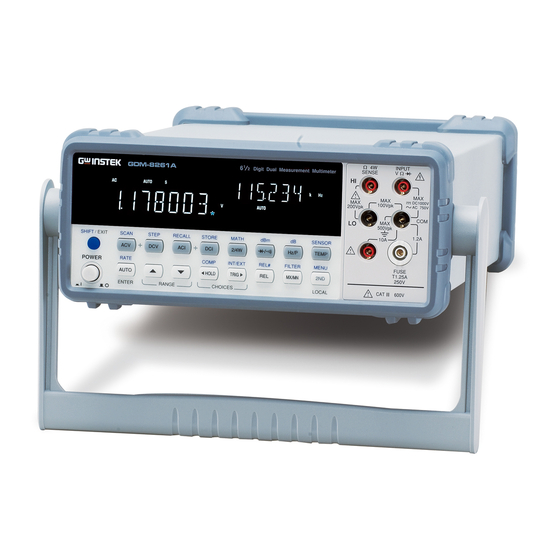
GETTING STARTED GDM-8261A Characteristics The GDM-8261A is a portable, dual-display digital multimeter suitable for a wide range of applications, such as production testing, research, and field verification. High DCV accuracy: 0.0035% Performance High current range: 10A High Voltage range: 1000V ... -
Page 12: Front Panel Overview
GDM-8261A User Manual Front Panel Overview Main Measurement Sense HI Display Keys Sense LO Terminal Terminal Input HI INPUT Terminal GDM-8261A SENSE Digit Dual Measurement Multimeter Input LO DC1000V 100Vpk AC 750V 200Vpk Terminal 500Vpk (COM port) 1.2A SHIFT / EXIT... -
Page 13: Measurement Keys (Upper Row)
GETTING STARTED Accepts HI sense line in 4W resistance Sense HI SENSE measurement. For details, see page 34. Terminal Accepts ground (COM) line in all Input LO measurements except the sense line in Terminal 4W Resistance (page 34). The maximum withstand voltage between this terminal and earth is 500Vpk. - Page 14 GDM-8261A User Manual Starts the step measurement (page SHIFT / EXIT SHIFT → DCV 113) using the optional scanner. (STEP) STEP Measures AC Current (page 32). Recalls a normal measurement SHIFT / EXIT SHIFT → ACI result, standard deviation (RECALL)
- Page 15 GETTING STARTED Measures dB (page 59). SHIFT / EXIT SHIFT + Hz/P (dB) Hz/P Measures Temperature (page 43). TEMP TEMP (Temperature) Selects the type of thermocouple SHIFT / EXIT SHIFT + TEMP used in the Temperature (SENSOR) measurement (page 44). SENSOR TEMP...
-
Page 16: Measurement Keys (Lower Row)
GDM-8261A User Manual Measurement Keys (lower row) As the AUTO key, selects the AUTO/ENTER AUTO measurement range automatically. ENTER As the Enter key, confirms the entered value. Selects the measurement update SHIFT / EXIT SHIFT → AUTO rate: Slow, Medium, or Fast (page (RATE) 25). - Page 17 GETTING STARTED Manually sets the reference value for SHIFT / EXIT SHIFT → REL the Relative value measurement (RELative base) (page 62). REL# Measures the Maximum or the MX/MN MX/MN Minimum value (page 61). (MAX/ MIN) Selects the digital filter type for the SHIFT / EXIT SHIFT →...
-
Page 18: Rear Panel Overview
GDM-8261A User Manual Rear Panel Overview Digital I/O Optional Power Cord Port Scanner Port Socket 16 CHANNEL MAX. RATING SCANNER 250V , 2A DIGITAL I / O RS232 LINE RATING 50 , 60 , 400Hz 25VA MAX. CAL KEY FUSE... - Page 19 GETTING STARTED Accepts a USB device cable for remote USB device port control; Type A, female connector. For remote control details, see page 132. CAL KEY Reserved for internal purposes such as CAL key port firmware updates and calibration. DIGITAL I / O Accepts a digital I/O cable for the Digital I/O port Hi/Lo limit tests;...
-
Page 20: Set Up
GDM-8261A User Manual Set Up Tilt Stand Pull out the Tilt stand steps handle sideways and rotate it. Place the unit horizontally, Or in the tilt stand position. Place the handle vertically for hand carry. -
Page 21: Power Up
3. Push to turn on the main power switch on the front panel. 4. The display shows the model name and the version for a few seconds. Example: GDM-8261A, V1.00 5. Followed by the default measurement settings. 6. And the interface I/O settings. - Page 22 GDM-8261A User Manual 7. Then the default setting appears. Example: DCV, Auto, 100mV range AUTO...
-
Page 23: Basic Measurement
BASIC MEASUREMENT ASIC MEASUREMENT 2/4W Hz/P TEMP Overview Basic Measurement Overview ........ 25 Refresh Rate ............25 Reading Indicator ........... 26 Manual/Automatic Triggering ........ 27 Voltage AC/DC Voltage Measurement ......... 27 Select Voltage Range ..........28 Voltage Conversion Table ........30 Crest Factor Table ........... - Page 24 GDM-8261A User Manual Temperature Temperature Measurement ........43 Select Thermocouple Type ........44 Set Reference Junction Temperature (T-CUP) ..45 Select Temperature Sensor Type ......46 Set User RTD ............47...
-
Page 25: Basic Measurement Overview
Refresh Rate Refresh rate defines how frequently the GDM-8261A Background captures and updates measurement data. A faster refresh rate yields a lower accuracy and resolution. A slower refresh rate yields a higher accuracy and resolution. -
Page 26: Reading Indicator
GDM-8261A User Manual Refresh Rate Function (Readings/s) Continuity / Diode DCV/DCI/100Ω~ 100MΩ (Accurate) 2400 DCV/DCI/100Ω~ 100MΩ (Quick) 3.38 ACV/ACI (sec/reading) Frequency / Period 1. Press the Shift key followed by RATE Selection steps SHIFT / EXIT the AUTO (RATE) key. The AUTO refresh rate switches to the next. -
Page 27: Ac/Dc Voltage Measurement
BASIC MEASUREMENT Manual/Automatic Triggering The GDM-8261A triggers according to the refresh rate. Automatic See the previous page for refresh rate setting details. triggering (default) Press the Trig key to trigger Manual TRIG measurement manually. The trigger triggering must be set to external (EXT) for manual triggering. -
Page 28: Select Voltage Range
GDM-8261A User Manual Select Voltage Range To turn the automatic range selection Auto range AUTO On/Off, press the AUTO key. Press the Up or the Down key to select Manual range the range. The AUTO indicator turns Off automatically. If the appropriate range is unknown, select the highest range. - Page 29 BASIC MEASUREMENT The DC voltage range should be manually selected when any of the following conditions are true: 1. When DCV measurement is used. 2. When the signals being measured contain both DC and AC components. 3. When the amplitude of the AC component in the measured signal is higher or lower than the dynamic range of the range being currently selected by auto-range function.
-
Page 30: Voltage Conversion Table
GDM-8261A User Manual Voltage Conversion Table This table shows the relationship between AC and DC reading in various waveforms. Waveform Peak to Peak (True RMS) Sine 2.828 1.000 0.000 PK-PK Rectified Sine 1.414 0.435 0.900 (full wave) PK-PK Rectified Sine 2.000... -
Page 31: Crest Factor Table
BASIC MEASUREMENT Crest Factor Table Crest factor is the ratio of the peak signal amplitude to the Background RMS value of the signal. It determines the accuracy of AC measurement. If the crest factor is less than 3.0, voltage measurement will not result in error due to dynamic range limitations at full scale. -
Page 32: Ac/Dc Current Measurement
GDM-8261A User Manual AC/DC Current Measurement The GDM-8261A has two input ports for current Background measurement. A 1A terminal for current less than 1.2A and a 10A port for measurements up to 10A. The GDM-8261A also features a ―Current Input Port Auto-Detect‖... -
Page 33: Select Current Range
BASIC MEASUREMENT Select Current Range To turn the automatic range Auto range AUTO selection On/Off, press the AUTO key. Press the Up or the Down key to Manual range select the range. AUTO indicator turns Off automatically. If the appropriate range is unknown, select the highest range. -
Page 34: 2W/4W Resistance Measurement
GDM-8261A User Manual The DC current range should be manually selected when the following conditions are true: 1. When DCI measurement is used. 2. When the signals being measured contain both DC and AC components. 3. When the amplitude of the AC component in the... -
Page 35: Select Resistance Range
BASIC MEASUREMENT AUTO 2. 2W/4W resistance mode display appears 2W or 4W + Ω Indicates 2W or 4W Resistance mode AUTO Indicates Automatic range selection 2nd display shows the Resistance range Connect the test lead. For 2-wire resistance, use the Ω (V) 3. - Page 36 GDM-8261A User Manual 10Ω 11.99999MΩ 10MΩ 100Ω 119.9999MΩ 100MΩ Note For more detailed range, see the specifications at page 217.
-
Page 37: Diode Test
BASIC MEASUREMENT Diode Test Diode test checks the forward bias characteristics of a Background diode by running a constant forward bias current, approx. 1mA, through the DUT. Press the key once. 1. Activate diode test 2. Diode mode display appears Indicates Diode test DIODE 2nd display shows the title... -
Page 38: Continuity Test
GDM-8261A User Manual Continuity Test Continuity test checks that the resistance in the DUT is Background low enough to be considered continuous (of conductive nature). Press the key twice. 1. Activate continuity test 2. Continuity mode display appears + Ω... -
Page 39: Set Continuity Threshold
BASIC MEASUREMENT Set Continuity Threshold Continuity threshold defines the maximum resistance Background allowed in the DUT when testing the continuity. 0 ~ 1000Ω, 1Ω resolution, 10Ω default Threshold Range SHIFT / EXIT MENU 1. Press the Shift key, the 2nd key, 1. -
Page 40: Select Beeper Setting
GDM-8261A User Manual Select Beeper Setting Beeper setting defines how the GDM-8261A notifies the Background continuity test result to the user. When the Beeper setting is off it will also turn the keypad sound off. Beeps when the test result is pass... -
Page 41: Frequency/Period Measurement
BASIC MEASUREMENT Frequency/Period Measurement To measure Frequency, press the 1. Activate Hz/P Hz/P key once. frequency/period measurement To measure the Period, press the Hz/P Hz/P Hz/P key twice. AUTO 2. Frequency (Period) mode display appears Hz (S) Indicates Frequency (period) measurement AUTO Indicates Automatic range selection FREQ... -
Page 42: Period Select Frequency/Period Voltage Range
GDM-8261A User Manual Select Frequency/Period Voltage Range To select between period/frequency Frequency/Period voltage range, press the 2nd key mode twice. To turn the automatic range Auto range AUTO selection On/Off, press the AUTO key. Press the Up or the Down key to Manual range select the range. -
Page 43: Temperature Measurement
BASIC MEASUREMENT Temperature Measurement The GDM-8261A can measure temperature using either Background thermocouples or RTD sensors. For thermocouples, the GDM-8261A accepts a thermocouple input and calculates the temperature from the voltage fluctuation. The thermocouple type and reference junction temperature are also considered. -
Page 44: Select Thermocouple Type
GDM-8261A User Manual Select Thermocouple Type The GDM-8261A accepts thermocouple inputs and Background calculates the temperature from the voltage difference of two dissimilar metals. Thermocouple type and reference junction temperature are also considered. Parameter Thermocouple Range Resolution -200 to +1000°C 0.002 °C -210 to +1200˚C 0.002 °C... -
Page 45: Set Reference Junction Temperature (T-Cup)
Set Reference Junction Temperature (T-CUP) When a thermocouple is connected to the GDM-8261A, Background the temperature difference between the thermocouple lead and the GDM-8261A input terminal should be taken into account and be cancelled; otherwise an erroneous temperature might be added. Type... -
Page 46: Select Temperature Sensor Type
SHIFT / EXIT (cancel) Select Temperature Sensor Type The GDM-8261A supports a number of thermocouple Background types as well as 2 or 4 wire RTD. It is important to specify the type of temperature sensor used. Parameter RTD type... -
Page 47: Set User Rtd
BASIC MEASUREMENT Press the Up and Down keys to 3. Select sensor highlight the RTD sensor type. PT 100, PT 3916, PT 385, F 100, D 100, RTD Type: USER Press the Enter key to confirm. 4. Confirm and SHIFT / EXIT AUTO Press the Exit key to go back to the... - Page 48 GDM-8261A User Manual Press the Down key twice. The RTD selection menu appears on the display. Use the Up/Down keys to select USER. Press Enter. The alpha coefficient 3. Open USER AUTO menu appears on the display. type menu ENTER Use the Left/Right key to move the 4.
-
Page 49: Dual Measurement
DUAL MEASUREMENT UAL MEASUREMENT Dual Measurement The dual measurement mode allows you to use the 2nd Background display to show another item, thus viewing two different measurement results at once. When the multimeter is used in dual measurement mode, both displays are updated from either a single measurement or from two separate measurements. - Page 50 GDM-8261A User Manual Amplifier Output INPUT AC Noise DC offset DC Power Supply Output INPUT AC ripple Power Supply DC output Monitor the voltage and current present on a component in a circuit or the output voltage and current of a DC power supply.
- Page 51 DUAL MEASUREMENT Measure the frequency response of devices such as amplifiers or buffers*. * The frequencies of the amplifier output must be within the DMM’s measurable AC bandwidth for the amplitude at a spot frequency to be measured accurately. Frequency Response INPUT The following table shows the available measurement...
- Page 52 GDM-8261A User Manual Press the 2nd key, then the target item (example: ACV). The display Measurement updates the measurement result. item setting (example: ACI + ACV) AUTO AUTO Shows the primary measurement result 1st Display Shows the secondary measurement 2nd Display...
- Page 53 DUAL MEASUREMENT When using the dual measurement function, the Connect the test connection method and number of test leads required leads and depends on the measurement combination. Use the measure connect diagrams below as guide when taking dual measurements. Voltage and Frequency/Period Measurement INPUT 2W/4W Resistance Measurement INPUT...
- Page 54 GDM-8261A User Manual Voltage/Frequency/Period and Current Measurement INPUT Load 0~1.2A 0~10A Note: DC Current measurements will be displayed as a negative value as the polarity of the current leads has been reversed. Please take into account the resistance of the test leads and internal resistance of the current connection as it is in series with the test circuit.
-
Page 55: Advanced Measurement
ADVANCED MEASUREMENT DVANCED MEASUREMENT FILTER REL# COMP INT/EXT MATH Hz/P MX/MN HOLD TRIG 2/4W Overview Advanced Measurement Overview ......56 Refresh Rate ............56 Reading Indicator ........... 57 Common Attribute: Manual/Automatic Triggering . 57 dBm/dB dBm/dB/W Measurement ........58 Measure dBm/W ............ 58 Measure dB ............ -
Page 56: Advanced Measurement Overview
● ● — Math Refresh Rate Refresh rate defines how frequently the GDM-8261A Background captures and updates measurement data. A faster refresh rate yields a lower accuracy and resolution. A slower refresh rate yields a higher accuracy and resolution. Consider these tradeoffs when selecting the refresh rate. -
Page 57: Reading Indicator
(slower than the normal captured refresh rate), indicating the DMM is in the waiting mode. Common Attribute: Manual/Automatic Triggering The GDM-8261A triggers according to the refresh rate. Automatic See the previous page for refresh rate setting details. triggering... -
Page 58: Dbm/Db/W Measurement
See page 76. dBm/dB/W Measurement Applicable to Using the ACV or DCV measurement result, the Background GDM-8261A calculates the dB, dBm or W value based on a reference resistance value in the following way. 10 x log (1000 x Vreading / Rref) dBm –... -
Page 59: Measure Db
Measure dB dB is defined as [dBm−dBmref]. When the dB Background measurement is activated, the GDM-8261A calculates the dBm using the reading at the first moment and stores it as dBmref. SHIFT / EXIT Press the Shift key followed by the Activate dB Hz/P key. - Page 60 GDM-8261A User Manual dB result appears Indicates dB measurement -00.617mV Indicates the present Voltage reading Press the 2nd key to see the dBm dBmref ref value. To cancel the dB measurement, SHIFT / EXIT Deactivate dB press the Shift key followed by the...
-
Page 61: Max/Min Measurement
ADVANCED MEASUREMENT Max/Min Measurement Applicable to 2/4W Hz/P TEMP Maximum and Minimum measurement stores the highest Background (maximum) or lowest (minimum) reading and shows it on the 1 display when the 2nd key is pressed. For Max measurement, press the 1. -
Page 62: Relative Value Measurement
GDM-8261A User Manual Relative Value Measurement Applicable to 2/4W Hz/P TEMP Relative measurement stores a value, typically the data at the Background moment, as the reference. The following measurement is shown as the delta between the reference. The reference value will be cleared upon exit. - Page 63 ADVANCED MEASUREMENT Indicates Relative measurement Shows the reference value (to full scale) 1st display Indicates Relative value modification 2nd display 2. Use the Left/Right key to HOLD TRIG move the flashing point (cursor), and use the Up/Down key to change the value.
-
Page 64: Hold Measurement
GDM-8261A User Manual Hold Measurement Applicable to 2/4W Hz/P TEMP The Hold Measurement function retains the current Background measurement data and updates it only when it exceeds the set threshold (as a percentage of the retained value). Press the Hold key. -
Page 65: Compare Measurement
ADVANCED MEASUREMENT Compare Measurement Applicable to 2/4W Hz/P TEMP Compare measurement checks and updates if the Background measurement data stays between the upper (high) and lower (low) limit specified. Press the Shift key, then the Hold COMP 1. Activate SHIFT / EXIT (Comp) key. - Page 66 GDM-8261A User Manual 3. Low limit setting Shows the low limit value 1st display Indicates low limit setting 2nd display 1. Use the Left/Right key to move HOLD TRIG the cursor (flashing point) between high/low setting, digits, and decimal point.
- Page 67 ADVANCED MEASUREMENT If the 2nd display shows 5. Result High High, the result is above the High limit. Digital I/O: FAIL Out (Pin 6) and HIGH Limit FAIL Out (Pin 7) are activated. If the 2nd display shows Low, the result is below the Low limit.
-
Page 68: Math Measurement
GDM-8261A User Manual Math Measurement Applicable to 2/4W Hz/P TEMP Math measurement runs four types of mathematical Background operations, MX+B, 1/X, Percentage and Stats, based on the other measurement results. Multiplies the reading (X) by the factor (M) Math type MX+B and adds/subtracts offset (B). - Page 69 ADVANCED MEASUREMENT 2. Change the parameter using the Up/Down key. 3. Press the Enter key to confirm AUTO editing and move to offset ENTER setting. 3. Set the offset Shows the offset (B) 1st display Indicates MX+B (The letter B flashes) 2nd display 1.
-
Page 70: Measure 1/X
GDM-8261A User Manual Measure 1/X Press the Shift key, the 2/4W (Math) 1. Activate 1/X MATH SHIFT / EXIT key, the Down key twice. The 1/X 2/4W setting appears. Press the Enter key to view the 1/X 2. View 1/X AUTO measurement result. -
Page 71: Statistics Calculations
ADVANCED MEASUREMENT 1. Use the Left/Right key to move HOLD TRIG the cursor (flashing point) between the digits and decimal point. 2. Change the parameter using the Up/Down key. 3. Press the Enter key to confirm AUTO editing. ENTER AUTO 3. - Page 72 GDM-8261A User Manual Press the Enter key to set the 2. Set Count AUTO number of measurements (counts) ENTER that will be used for the Stats function. The Count menu appears. Shows the count number as continuous 1st display Indicates the count setting 2nd display 1.
- Page 73 ADVANCED MEASUREMENT 3. Press the Enter key to confirm AUTO editing and to start ENTER measurement. AUTO 3. View Data MATH Shows the current count 1st display number/measurement Indicates the count measurement mode. 2nd display Indicates Math operation MATH Press the 2nd key to cycle through the different statistical data measurements.
-
Page 74: System/Display Configuration
GDM-8261A User Manual YSTEM/ ISPLAY CONFIGURATION RATE FILTER MENU AUTO MX/MN Refresh Rate Refresh Rate Setting ..........75 View Serial Number ..........75 Trigger Manual/Automatic Triggering ........ 76 Use External Trigger ..........76 Set Trigger Delay ............ 78 Filter Settings Digital Filter Overview ........... -
Page 75: Refresh Rate Setting
SYSTEM/DISPLAY CONFIGURATION Refresh Rate Setting Refresh rate defines how frequently the GDM-8261A Background captures and updates the measurement data. A faster refresh rate yields a lower accuracy and resolution. Slower refresh rates yield a higher accuracy and resolution. Consider this trade-off when selecting the refresh rate. -
Page 76: Trigger Setting
See below triggering for details. Use External Trigger The GDM-8261A uses the internal trigger by default, for Background example to count the frequency and the period. Using an external trigger allows customized triggering conditions. Connect the external trigger signal to the Digital I/O Signal port located on the rear panel. - Page 77 SYSTEM/DISPLAY CONFIGURATION DB-9, female Digital I/O pin High Limit FAIL Out LOW Limit FAIL Out assignment FAIL Out EOM Out 7 8 9 1 2 3 4 5 VCC Out PASS Out External Trigger In Digital (chassis) Ground Press the Shift key followed by the 1.
-
Page 78: Set Trigger Delay
GDM-8261A User Manual Set Trigger Delay Trigger delay defines the time delay between triggering Background and measurement start. The default is set at 10ms. 1. Press the Shift key, the 2nd MENU Panel operation SHIFT / EXIT (Menu) key, the Right key, the Down key. -
Page 79: Filter Setting
SYSTEM/DISPLAY CONFIGURATION Filter Setting Digital Filter Overview The GDM-8261A’s internal digital filter converts the Filter basics analog input signal into digital format before passing it to internal circuits for processing. The filter affects the amount of noise included in the measurement result. -
Page 80: Digital Filter Setting
GDM-8261A User Manual Filter count defines the number of samples to be Filter count averaged per reading. More samples offer low noise but a long delay. Less samples offer high noise but a short delay. 2 ~ 100 Range Filter window defines the threshold for when the digital Filter window filter data is updated again. - Page 81 SYSTEM/DISPLAY CONFIGURATION 2. Select the filter type using the Up/Down key. 3. Move the cursor to filter count HOLD TRIG using the Left/Right key. Change the value using the Up/Down key. 4. Press the Enter key to confirm Set Filter Window AUTO editing.
-
Page 82: Analog Filter Settings
GDM-8261A User Manual Analog Filter Settings The analog filter is a single order low pass filter that can Background be turned on to attenuate the AC components from a DC signal. This will effectively eliminate the AC component from influencing the automatic range settings. -
Page 83: Display Setting
SYSTEM/DISPLAY CONFIGURATION 6. Press the Enter key to confirm SHIFT / EXIT AUTO your selection. Press the Exit ENTER key to go back to the default display. Display Setting Display Light Setting The display light setting adjusts the brightness of the Background display reading. -
Page 84: Measurement Configuration Settings
GDM-8261A User Manual 4. Select the level using the Up/Down key. 5. Press the Enter key to confirm SHIFT / EXIT AUTO your selection. Press the Exit ENTER key to go back to the default display. Measurement Configuration Settings D-Shift Settings... -
Page 85: Input Resistance Setting
SYSTEM/DISPLAY CONFIGURATION Shows the D-Shift setting 1st display 4. Select the setting using the Up/Down keys. 5. Press the Enter key to confirm SHIFT / EXIT AUTO your selection. Press the Exit ENTER key to go back to the default display. -
Page 86: Ac Bandwidth Setting
GDM-8261A User Manual Shows the input resistance setting 1st display 4. Select the setting using the Up/Down keys. 5. Press the Enter key to confirm SHIFT / EXIT AUTO your selection. Press the Exit ENTER key to go back to the default display. -
Page 87: Current Input Port Auto-Detect Setting
SYSTEM/DISPLAY CONFIGURATION 3. Press the Down key. The input bandwidth setting appears. Shows the bandwidth setting 1st display 4. Select the setting using the Up/Down keys. 5. Press the Enter key to confirm SHIFT / EXIT AUTO your selection. Press the Exit ENTER key to go back to the default display. -
Page 88: Adc Setting
Auto zeroing is used to prevent measurements from drifting by taking offset measurements. Off, On (default=On) Setting The combined offset from the input buffer, A/D driver Theory and ADC is called the total offset. Due to temperature variations inside the GDM-8261A, the offsets for the... - Page 89 SYSTEM/DISPLAY CONFIGURATION Buffer, A/D driver and ADC vary over time, and thus the total offset will also vary over time. Auto Zero deducts this total offset from the measured signal to obtain a more accurate reading. If Auto Zero is turned off, this total offset will not be deducted from the measured signal.
-
Page 90: Auto-Gain
GDM-8261A User Manual Shows A-Zero setting 1st display 3. Select the setting using the Up/Down key. 4. Press the Enter key to confirm SHIFT / EXIT AUTO your selection. Press the Exit ENTER key to go back to the default display. - Page 91 SYSTEM/DISPLAY CONFIGURATION 2. Press the Down key and then HOLD the Left key twice to choose A-GAIN. Press the Down key. HOLD The A-GAIN setting appears. Shows A-Zero setting 1st display 3. Select the setting using the Up/Down key. 4. Press the Enter key to confirm SHIFT / EXIT AUTO...
-
Page 92: Adc Speed Setting
GDM-8261A User Manual ADC Speed Setting The analog to digital converters have a Quick and Background Accurate Speed setting. The ADC Speed settings only apply to DCV, DCI or 2/4W resistance measurements. The ADC Speed settings can only be set if DCV, DCI or 2/4W mode is active. -
Page 93: Frequency / Period Settings
SYSTEM/DISPLAY CONFIGURATION 4. Use the Up/Down keys to select either ACCUR or QUICK. 5. Press the Enter key to confirm SHIFT / EXIT AUTO your selection. Press the Exit ENTER key to go back to the default display. Frequency / Period Settings Input Port Selection The INJACK settings set which input port is used for Background... - Page 94 GDM-8261A User Manual 4. Press the Enter key to confirm SHIFT / EXIT AUTO your selection. Press the Exit ENTER key to go back to the default display.
-
Page 95: Period Settings Gate Time Setting
SYSTEM/DISPLAY CONFIGURATION Gate Time Setting The gate time settings determine the accuracy of the Background frequency and period measurements. The gate time settings are the equivalent to the Fast, Medium and Slow rate settings. 10ms, 100ms, 1000ms Setting The gate time settings are analogous to the rate settings. Rate Settings Function Digits... -
Page 96: Identification Settings
GDM-8261A User Manual Identification Settings Changing the Identification String The *IDN? query returns the manufacturer, model Background number, serial number and system firmware version number. When LANG is set to COMP, a user defined manufacturer and model number is returned with the *IDN? query. -
Page 97: Store/Recall
STORE/RECALL TORE/ ECALL The GDM-8261A can store and recall measurement history (for up to 9999 counts) as well as the instrument settings. For storing and recalling measurement results using the Scanner, see page 103. STORE RECALL Store Measurement Record ........98 Recall Measurement Record ........ -
Page 98: Store Measurement Record
GDM-8261A User Manual Store Measurement Record The GDM-8261A can log up to 9999 measurement Background results (counts) which can be stored and recalled later for analysis. Basic measurement statistics such as Maximum, Minimum, Average value as well as Standard Deviation are also recorded with the data. -
Page 99: Recall Measurement Record
STORE/RECALL Recall Measurement Record The GDM-8261A can recall previously recorded Background measurement results for observation and analysis. The Standard Deviation, Maximum Value, Minimum Value and Average Value can also be viewed. Store/recall measurement history is not applicable to the Not applicable to... -
Page 100: Save Instrument Settings
GDM-8261A User Manual Save Instrument Settings The GDM-8261A can save up to 5 instrument settings. Background The settings can save the state, function, I/O and range. Upon powering up, the current instrument setting is displayed. Save (1-5), Del-All Parameter Main display parameters... -
Page 101: Recall Instrument Settings
STORE/RECALL Shows the memory number 1st display 4. Select the memory number using the Up/Down key or select Del-All to delete the save settings in memory. 5. Press the Enter key to confirm SHIFT / EXIT AUTO your selection. Press the Exit ENTER key to go back to the default display. - Page 102 GDM-8261A User Manual 3. Press the Down key to enter the Recall menu. Shows the memory number 1st display 4. Select the memory number using the Up/Down key. 5. Press the Enter key to confirm SHIFT / EXIT AUTO your selection. Press the Exit ENTER key to go back to Recall menu.
-
Page 103: Scanner (Optional)
SCANNER (OPTIONAL) CANNER (OPTIONAL) The optional scanner, GDM-SC1, lets you effectively measure multiple channels connected to a single GDM-8261A DMM. SCAN STEP Installation GDM-SC1 Scanner Specifications ......104 Configure Scanner ..........104 Select Channel Group and Enable Scanner ..106 Connect Wires ............ -
Page 104: Gdm-Sc1 Scanner Specifications
GDM-8261A User Manual GDM-SC1 Scanner Specifications 16 pairs 2Arms (ch17, 2-wire channel Maximum current ch18) 8 pairs 2/4 wire 4-wire channel Resistance N/A (internal) Single wire channel Cold junction 250Vrms Screw terminal Maximum voltage Connection Scanner Installation Configure Scanner 1. Take off four screws from the bottom panel of the Open Scanner scanner. - Page 105 SCANNER (OPTIONAL) 3. The connection terminals are revealed. 16 general purpose channels are available, 8 on the left Overview row, 8 on the right row. Current (ACI, DCI) measurement uses 2 extra channels. All channels are fully isolated (Hi and Lo). Refer to the below table for measurement and test line Scan/Step connections.
-
Page 106: Select Channel Group And Enable Scanner
Set the jumper J8 in the center of the board to the Select group MASTER configuration. Move the jumper to the right (Jumper J8) (pins 2-3) to select CH1xx (101 ~ 118). The GDM-8261A does not support the SLAVE operation mode with the optional scanner. CH201-218 SLAVE CH101-118... -
Page 107: Connect Wires
SCANNER (OPTIONAL) Set the jumper J9 on the rear side of the board Enable scanner accordingly. Move the jumper up (pins 3-2) to disable the (Jumper J9) scanner, and down (pins 2-1) to enable the scanner. Disabled Enabled Connect Wires Make sure the wires have at least the same voltage and Wire selection current capacity as the maximum ratings of the... - Page 108 GDM-8261A User Manual 2. Route the wires as shown below via the two openings (left and right) at the front cover. When using thermocouple wiring, please use extension wires so that the cold junction points are Note external to the scanner card. Connecting...
- Page 109 SCANNER (OPTIONAL) 4. Close the top cover and tighten the screw from the bottom. Print out the configuration record list on page 112, fill in Configuration the details, and keep it with the GDM-8261A. Record...
-
Page 110: Insert Scanner
GDM-8261A User Manual Insert Scanner Turn the Power Off and take out the power cord. Power Off Take off the two screws on the slot corners to remove Open the the optional slot cover. Keep the screws for later reuse. - Page 111 SCANNER (OPTIONAL) Insert the scanner bottom-side-up (already configured Insert the according to the procedures on page 104) into the slot. scanner Close the cover by tightening the screws. Connect the power cord and turn On the power. Power On Do not input voltages exceeding 250Vrms to the front input terminals while the scanner module is installed.
-
Page 112: Scanner Configuration Record
GDM-8261A User Manual Scanner Configuration Record Measurement Channel Wire color Note type CH10 CH11 CH12 CH13 CH14 CH15 CH16 CH17 CH18 CARD INPUT H CARD SENSE H AMPS... -
Page 113: Setup Scan
(Continuous) end of the loop count. Then it goes into the idle mode. The GDM-8261A stays in the idle mode External by default. The trigger timing is manually (Manual) controlled by the user from the front panel using the Trig key. -
Page 114: Setup Simple Scan
GDM-8261A User Manual Trigger delay time Scan Timer Timer Timer Count# 10 11 12 Delay Delay Delay Example: Scan channels 1~4 with a count setting of 12. Measures a single channel in the specified Step range (Channel MIN~MAX)at each trigger event. Timer settings (page 115) apply for each channel. - Page 115 SCANNER (OPTIONAL) 3. Press the Down key again. The Starting (Minimum) channel setting appears. 4. Move the cursor to the channel HOLD TRIG using the Left/Right key, and change the value using the Up/Down key. 101 ~ 118 Range 5. When finished, press the Enter AUTO key.
-
Page 116: Setup Advanced Scan
GDM-8261A User Manual 9. Press the Enter key. The loop AUTO (step) Count setting appears. ENTER 10. Move the cursor to the count HOLD TRIG number using the Left/Right key, and change the value using the Up/Down key. 1 ~ 999 Range 11. - Page 117 SCANNER (OPTIONAL) 4. Move the cursor to the channel HOLD TRIG using the Left/Right key, and change the value using the Up/Down key. 101 ~ 118 Range 5. When finished, press the Enter AUTO key. The End (Maximum) ENTER channel setting appears. 6.
- Page 118 GDM-8261A User Manual 1 ~ 999 Range 10. Move the cursor to the count HOLD TRIG number using the Left/Right key, and change the value using the Up/Down key. 11. When finished, press the Enter AUTO key. The channel setting appears.
-
Page 119: Use External Trigger
SCANNER (OPTIONAL) Use External Trigger The GDM-8261A uses the internal trigger by default. Background Using an external trigger allows customized triggering. Connect the external trigger signal to the Digital I/O Signal port located on the rear panel. connection DB-9, female... -
Page 120: Run Scan
GDM-8261A User Manual Run Scan Overview Measures all the specified channel ranges Scan operation Scan at each trigger event. The timer settings type (page 115) apply to each scan. Measures a single channel in the specified Step range at each trigger event. The timer settings (page 115) apply to each channel. -
Page 121: Recall Scan/Step Result
SCANNER (OPTIONAL) Recall Scan/Step Result 1. After the Scan/Step is RECALL Panel operation SHIFT / EXIT completed, the data is stored internally. Press the Shift key followed by the ACI (Recall) key. 2. The first channel appears. (example: channel 101) 3. - Page 122 GDM-8261A User Manual 3. Press the Down key. The channel selection appears. 4. Move the cursor to the channel HOLD TRIG using the Left/Right key, and change the channel number using the Up/Down keys. 5. When finished, press the Enter AUTO key.
-
Page 123: Digital I/O
DIGITAL I/O IGITAL I/O The rear panel Digital I/O terminal outputs the result of Compare measurements to external devices. COMP HOLD Terminal Digital I/O Terminal Configuration ...... 124 configuration Application Application: Compare measurement ....125 Application: External trigger ......... 128... -
Page 124: Digital I/O Terminal Configuration
GDM-8261A User Manual Digital I/O Terminal Configuration The digital I/O terminal outputs the result of Compare Background measurements to control external devices. By providing separate VCC power for the terminal, the outputs can also be used as a power source for TTL and CMOS circuits. - Page 125 DIGITAL I/O PASS signal Output. Activates when the Pin5 compare result is PASS. FAIL signal Output. Activates when the Pin6 compare result is FAIL. HIGH Limit FAIL signal Output. Activates Pin7 when the compare result is FAIL due to violating the HIGH Limit. LOW Limit FAIL signal Output.
- Page 126 GDM-8261A User Manual 2. Change the parameter using the Up/Down key. 3. Press the Enter key to confirm AUTO editing and move to the low ENTER limit setting. 3. Low limit setting Shows the low limit value 1st display Indicates low limit setting...
- Page 127 DIGITAL I/O Digital I/O: FAIL Out (Pin 6) and LOW Limit FAIL Out (Pin 8) are activated. If the 2nd display shows Pass Pass, the result is staying between the High and the Low limit. Digital I/O: PASS Out (Pin 5) is activated.
- Page 128 GDM-8261A User Manual Application: External trigger The GDM-8261A uses the internal trigger by default, for Background example to count the frequency and the period. Using an external trigger allows for customized triggering conditions. Connect the external trigger signal to the Digital I/O Signal port located on the rear panel.
- Page 129 DIGITAL I/O Press the Trig key to start triggering 2. Start trigger TRIG manually. The indicator turns AUTO The reading indicator stays On before triggering. Reading indicator After triggering, the indicator flashes according to the external signal trigger timing. Press the Shift key followed by the INT/EXT Exit external SHIFT...
-
Page 130: Remote Control
GDM-8261A User Manual EMOTE CONTROL Overview .............. 132 Interface Configure USB Interface ........132 Configure RS-232C Interface ........ 133 Set the EOL Character .......... 134 Set the Separation Character ....... 135 Set the Return Format .......... 136 Insert GPIB Card ..........138 Configure GPIB Interface ........ - Page 131 REMOTE CONTROL TRIGger Commands ..........197 SYSTem Related Commands ......... 200 STATus Report Commands ........203 RS-232C Interface Commands ......203 IEEE 488.2 Common Commands ......203 ROUTe Commands ..........205...
-
Page 132: Configure Interface
GDM-8261A User Manual Configure Interface Overview USB 1.1 or 2.0, TypeA, female Interface type USB Device connector. D-sub 9 pin, male connector. Baud rate: RS-232C 230400/115200/57600/38400/19200/ 9600. Data bits: 8, Parity: none, Stop bits: 1, Flow control: none. 24 Pin female GPIB port... -
Page 133: Configure Rs-232C Interface
REMOTE CONTROL 3. Press the Down key. The USB ON/OFF selection appears. 4. Press the Up/Down key to select ON or OFF. SHIFT / EXIT AUTO 5. Press the Enter key followed by the Exit key. The USB setting is ENTER stored and the display goes back to the default display. -
Page 134: Set The Eol Character
GDM-8261A User Manual 4. Press the Down or UP keys repeatedly to select the baud rate. 2304001152005760038400192009600 SHIFT / EXIT 5. Press the Enter key followed by AUTO the Exit key. The RS-232 setting ENTER is stored and the display goes back to the default display. -
Page 135: Set The Separation Character
REMOTE CONTROL 1. Press the Shift key, the 2nd MENU Configuration SHIFT / EXIT (Menu) key, the left key repeatedly until the TX TERM configuration menu appears. HOLD 2. Press the Down key. The EOL menu appears. 3. Press the Down key. The EOL selection menu appears. -
Page 136: Set The Return Format
GDM-8261A User Manual 1. Press the Shift key, the 2nd MENU Configuration SHIFT / EXIT (Menu) key, the left key repeatedly until the TX TERM configuration menu appears. HOLD 2. Press the Down key and then TRIG the Right key. The SEP selection display appears. - Page 137 REMOTE CONTROL Format Description Example Value +0.503E-4 Value, Unit +0.503E-4, V DC Value, Count# +0.503E-4, +00001# Value, Unit, Count# +0.503E-4, V DC, V+U+C +00001# 1. Press the Shift key, the 2nd MENU Configuration SHIFT / EXIT (Menu) key, the left key repeatedly until the TX TERM configuration menu appears.
-
Page 138: Insert Gpib Card
GDM-8261A User Manual Insert GPIB Card Turn the Power Off and take out the power cord. Power Off Take off the two screws on the slot corners to remove Open the the optional communication port cover. Keep the screws GDM-8261A for later reuse. -
Page 139: Configure Gpib Interface
REMOTE CONTROL Connect the power cord and turn On the power. Power On Configure GPIB Interface 1. Press the Shift key, the 2nd MENU GPIB port SHIFT / EXIT (Menu) key, and then the left key configuration repeatedly until the I/O configuration menu appears. - Page 140 GDM-8261A User Manual 5. To continue to the GPIB AUTO address configuration, press the ENTER Enter key. The GPIB address configuration menu appears. Shows the GPIB address. 1st display Indicates GPIB address setting 2nd display 6. Change the address using the...
-
Page 141: Insert Ethernet Card
Turn the Power Off and take out the power cord. Power Off Take off the two screws on the slot corners to remove Open the the optional communication port cover. Keep the screws GDM-8261A for later reuse. optional communication port... -
Page 142: Activate Ethernet Interface
GDM-8261A User Manual Insert the Ethernet card into the slot. Close the cover by Insert the tightening the screws. Ethernet card Connect the power cord and turn on the power. Power On Execute the INIT function to initialize the LAN settings, Initialize see page 154 for details. - Page 143 REMOTE CONTROL 2. Press the Down key and the Left key repeatedly until LAN selection display appears. HOLD Note: The LAN menu will be selectable only when the LAN card is installed. 3. Press the Down key. The LAN ON/OFF selection appears. 4.
-
Page 144: Configure Ethernet Interface (Reset)
GDM-8261A User Manual Configure Ethernet Interface (RESET) The RESET command is used to reset the Ethernet card Background when new settings have been made. When the DHCP, IP, subnet, gateway or DNS settings have been edited, use the RESET command to validate the changes and reset the Ethernet card to the new configuration settings. -
Page 145: Configure Ethernet Interface To Dhcp
(see page 38). Configure Ethernet Interface to DHCP The GDM-8261A supports DHCP to have an IP address Background and other configuration parameters automatically assigned by a DHCP server. If the DHCP server is absent, the Ethernet card will automatically assign an IP address between 169.254.1.0 and 169.254.254.255 using... -
Page 146: Configure Ethernet Ip
1. To make any changes take effect, set RESET to YES. 2. Reset LAN See page 144 for details. card Configure Ethernet IP The GDM-8261A supports manually setting of the IP Background addresses, including the subnet mask, gateway and DNS. MENU SHIFT / EXIT 1. - Page 147 REMOTE CONTROL 2. Press the Down key and the TRIG Right key twice. The IP selection display appears. TRIG Note: The IP address can only be edited if DHCP is off. 3. Press the Down key. The IP address selection appears. IP2 IP3 The IP address is divided in 4 groups;...
- Page 148 GDM-8261A User Manual 7. Repeat steps 4 to 6 for IP2, IP3 and IP4. SHIFT / EXIT 8. Press the Exit key to exit from the configuration menu. MENU SHIFT / EXIT 1. Press the Shift key, the 2nd 2. Subnet...
- Page 149 REMOTE CONTROL 4. Use the Left/Right keys to HOLD TRIG move the cursor to the S1 value and select a digit. 5. Press the Up/Down key to edit the selected digit. 6. Press the Enter key to confirm AUTO and automatically go onto S2. ENTER 7.
- Page 150 GDM-8261A User Manual 2. Press the Down key and the Right key repeatedly until the GATEWAY selection display TRIG appears. Note: The gateway can only be edited if DHCP is off. 3. Press the Down key. The GATEWAY address selection appears.
- Page 151 REMOTE CONTROL SHIFT / EXIT 8. Press the Exit key to exit from the configuration menu. MENU SHIFT / EXIT 1. Press the Shift key, the 2nd 4. DNS (Menu) key, and the Left key Configuration repeatedly until the SET LAN HOLD configuration menu appears.
-
Page 152: View Mac Address
GDM-8261A User Manual 5. Press the Up/Down key to edit the selected digit. 6. Press the Enter key to confirm AUTO and automatically go onto D2. ENTER 7. Repeat steps 4 to 6 for D2, D3 and D4. SHIFT / EXIT 8. -
Page 153: Configure Telnet Port
/ EXIT 4. Press the Exit key to exit from the configuration menu. Configure Telnet Port The GDM-8261A can set the telnet port used for virtual Background private networks. By default the telnet port is set to port MENU SHIFT / EXIT 1. -
Page 154: Return To Initial Settings
Exit key to confirm and exit ENTER the configuration menu. Return to Initial Settings The INIT function is used to return the GDM-8261A Background back to the original LAN settings. This will also reset the web password back to 123456 if the password has been forgotten. - Page 155 REMOTE CONTROL MENU SHIFT / EXIT 1. Press the Shift key, the 2nd Return to Initial (Menu) key, and the Left key Settings repeatedly until the SET LAN HOLD configuration menu appears. Note: SET LAN will only be available after LAN has been activated in the I/O menu, see page 142.
-
Page 156: View Web Password Settings
GDM-8261A User Manual If the GDM-8261A is returned to the initial settings, a reset is performed automatically (page 144) after exiting Note the configuration menu. Resetting the Ethernet card takes approximately 5 to 10 seconds. The continuity icon ( ) is used to indicate the status of... -
Page 157: Remote Terminal Session (Telnet)
Note password if the password has been forgotten. Remote Terminal Session (Telnet) A terminal application can be used to remotely control Background the GDM-8261A via the telnet protocol. 1. Establish a connection via the Operation Page 141, 142 Ethernet port. - Page 158 GDM-8261A User Manual 3. Run this query via the terminal application: *idn? The command will return the instrument manufacturer, model number, serial number and firmware version in the following format: >GWInstek,GDM8261A,00000000,1.0 4. See page 163 for more details on remote commands.
-
Page 159: Web Control Interface
The web control interface allows a web browser to modify parameter settings, remotely operate, control and monitor the GDM-8261A with a virtual front panel that mimics the GDM-8261A front panel interface. Telnet parameters can also be edited by using the web control interface so that... - Page 160 2. The virtual control panel appears. 3. All the basic panel operations using the virtual control panel are nearly identical to using the actual GDM-8261A, with a few notable exceptions: The scan function is not accessible. Store/recall is not accessible.
- Page 161 The current Ethernet settings can be viewed and 3. View and modified from the web control interface. Settings that Modify LAN cannot be edited using the GDM-8261A front panel, Configuration such as the web password, can be edited from the web control interface.
- Page 162 GDM-8261A User Manual 3. The View & Modify Configuration page allows you View the instrument name, firmware revision of the Ethernet card, IP address and MAC address. Set the IP address to DHCP or static. Configure the module host name, UPnP port number, telnet port number and telnet timeout time.
-
Page 163: Command Syntax
Any NR1,NR2 or NR3 value. The GDM-8261A automatically translates MIN, MAX to the Minimum (min) or Maximum (max) value available. Default setting value. The GDM-8261A automatically translates the command Automatic parameter into the closest available value. parameter range CONF:VOLT:DC 1 (Sets the selection... -
Page 164: Command Set
GDM-8261A User Manual Command separator, user configurable EOL or , Message (excluding GPIB), see page 135. Separator Square brackets denote function Square Brackets commands or parameters that can be omitted from the command or query. For example the query, [SENSe:]UNIT? - Page 165 REMOTE CONTROL CONFigure2:FUNCtion? ................176 CONFigure2:RANGe? ................176 CONFigure2:AUTO .................. 176 CONFigure2:AUTO? ................176 MEASure:VOLTage:DC? ................177 MEASure:VOLTage:AC? ................177 MEASure:CURRent:DC? ................177 MEASure:CURRent:AC? ................177 MEASure:RESistance? ................177 MEASure:FRESistance? ................178 MEASure:FREQuency? ................178 MEASure:PERiod? ..................178 MEASure:CONTinuity? ................178 MEASure:DIODe? ..................
- Page 166 GDM-8261A User Manual [SENSe:]TEMPerature:FRTD:TYPE? ............182 [SENSe:]TEMPerature:FRTD:ALPHa ............182 [SENSe:]TEMPerature:FRTD:ALPHa? ............182 [SENSe:]TEMPerature:FRTD:BETA ............182 [SENSe:]TEMPerature:FRTD:BETA? ............182 [SENSe:]TEMPerature:FRTD:DELTa ............182 [SENSe:]TEMPerature:FRTD:DELTa? ............182 [SENSe:]DETector:RATE ................182 [SENSe:]DETector:RATE? ................182 [SENSe:]AVERage:TCONtrol ..............183 [SENSe:]AVERage:TCONtrol? ..............183 [SENSe:]AVERage:COUNt ................ 183 [SENSe:]AVERage:COUNt? ..............183 [SENSe:]AVERage:WINDow ..............
- Page 167 REMOTE CONTROL [SENSe:]DIGital:SHIFt? ................186 [SENSe:]UNIT................... 186 [SENSe:]UNIT? ..................186 [SENSe:]FUNCtion[1/2]? ................186 [SENSe:]FUNCtion[1/2] ................186 [SENSe:]VOLTage:DC:RANGe ..............186 [SENSe:]VOLTage:DC:RANGe? ..............187 [SENSe:]VOLTage:AC:RANGe ..............187 [SENSe:]VOLTage:AC:RANGe? ..............187 [SENSe:]CURRent:DC:RANGe ..............187 [SENSe:]CURRent:DC:RANGe? ............... 187 [SENSe:]CURRent:AC:RANGe ..............187 [SENSe:]CURRent:AC:RANGe? ..............187 [SENSe:]RESistance:RANGe ..............
- Page 168 GDM-8261A User Manual [SENSe:]VOLTage:DC:RESolution? ............190 [SENSe:]VOLTage:AC:RESolution ............190 [SENSe:]VOLTage:AC:RESolution? ............190 [SENSe:]CURRent:DC:RESolution ............190 [SENSe:]CURRent:DC:RESolution? ............191 [SENSe:]CURRent:AC:RESolution ............191 [SENSe:]CURRent:AC:RESolution? ............191 [SENSe:]RESistance:RESolution .............. 191 [SENSe:]RESistance:RESolution? ............. 191 [SENSe:]FRESistance:RESolution ............191 [SENSe:]FRESistance:RESolution? ............191 [SENSe:]CONTinuity:RESolution ............. 191 [SENSe:]CONTinuity:RESolution? ............191 [SENSe:]DIODe:RESolution ..............
- Page 169 REMOTE CONTROL CALCulate:REL:REFerence? ..............195 CALCulate:LIMit:LOWer ................195 CALCulate:LIMit:LOWer? ................. 195 CALCulate:LIMit:UPPer ................195 CALCulate:LIMit:UPPer? ................195 CALCulate:DB:REFerence ................ 195 CALCulate:DB:REFerence? ............... 195 CALCulate:DBM:REFerence ..............195 CALCulate:DBM:REFerence? ..............195 CALCulate:STORe:COUNt ............... 196 CALCulate:STORe:COUNt? ..............196 CALCulate:AVERage:COUNt ..............196 CALCulate:AVERage:COUNt? ..............196 CALCulate:AVERage:MINimum? .............
- Page 170 GDM-8261A User Manual TRIGger:COUNt? ..................199 TRACe:DATA? ................... 199 TRACe:CLEar .................... 199 SYSTem:BEEPer:STATe ................200 SYSTem:BEEPer:STATe? ................200 SYSTem:BEEPer:ERRor ................200 SYSTem:BEEPer:ERRor? ................200 SYSTem:ERRor? ..................200 SYSTem:VERSion? ..................200 SYSTem:DISPlay ..................200 SYSTem:DISPlay? ..................200 SYSTem:OUTPut:FORMat ............... 200 SYSTem:OUTPut:FORMat? ..............201 SYSTem:OUTPut:EOF ................
- Page 171 REMOTE CONTROL *OPC ......................204 *PSC?......................204 *PSC ......................204 *RST ......................204 *SRE? ......................204 *SRE ......................204 *STB? ......................204 *TRG ......................204 ROUTe:CLOSe ..................205 ROUTe:OPEN:ALL ................... 205 ROUTe:MULTiple:OPEN ................205 ROUTe:MULTiple:STATe? ................. 205 ROUTe:MULTiple:CLOSe ................. 205 ROUTe:FUNCtion ..................
-
Page 172: Configure Commands
GDM-8261A User Manual CONFigure Commands CONFigure:VOLTage:DC Sets measurement to DC Voltage on the first display and specifies range/resolution. Parameter: [None] | [Range(<NRf> | MIN | MAX | DEF),Resolution(<NRf>| MIN | MAX | DEF)] Example: CONF:VOLT:DC 1,MAX Sets the voltage range to 1 volt and the resolution to the maximum. -
Page 173: Configure:fresistance
REMOTE CONTROL CONFigure:FRESistance Sets measurement to 4W Resistance on the first display and specifies the range/resolution. Parameter: [None] | [Range(<NRf> | MIN | MAX | DEF),Resolution(<NRf> | MIN | MAX | DEF)] Example: CONF:FRES 10e3,MAX Ω Sets the measurement mode to 4W with a range of 10k at the maximum resolution. -
Page 174: Secondary Display: Configure2 Commands
GDM-8261A User Manual CONFigure:TEMPerature:RTD Sets the measurement mode to 2W RTD measurement mode on the first display. Sets the sensor type. Parameter: [None] | [Type(PT100 | D100 | F100 | PT385 | PT3916 | USER)] Example: CONF:TEMP:RTD PT100 Sets the sensor type to PT100 and sets the measurement mode to 2W RTD CONFigure:FUNCtion? Returns the current function on 1st display. -
Page 175: Configure2:Voltage:ac
REMOTE CONTROL CONFigure2:VOLTage:AC Sets measurement to AC Voltage on the second display and specifies range/resolution. Parameter: [None] | [Range(<NRf> | MIN | MAX | DEF),Resolution(<NRf> | MIN | MAX | DEF)] Example: CONF2:VOLT:AC Sets the measurement mode to AC voltage. CONFigure2:CURRent:DC Sets measurement to DC Current on the second display and specifies range/resolution. -
Page 176: Configure2:Frequency
GDM-8261A User Manual CONFigure2:FREQuency Sets measurement to Frequency on the second display and specifies range/resolution. Parameter: [None] | [Range(<NRf> | MIN | MAX | DEF),Resolution(<NRf> | MIN | MAX | DEF)] Example: CONF2:FREQ MAX,MAX Sets the frequency measurement range to max and the resolution to max. -
Page 177: Measure Commands
REMOTE CONTROL Measure Commands MEASure:VOLTage:DC? Returns the DC voltage measurement on the first display. Parameter: [None] | [Range(<NRf> | MIN | MAX | DEF),Resolution(<NRf>| MIN | MAX | DEF)] Example: MEAS:VOLT:DC ? >+0.488E-4 Returns the DC voltage measurement as 0.0488 mV. MEASure:VOLTage:AC? Returns the AC voltage measurement on the first display. -
Page 178: Measure:fresistance
GDM-8261A User Manual MEASure:FRESistance? Returns the 4W resistance measurement on the first display. Parameter: [None] | [Range(<NRf> | MIN | MAX | DEF),Resolution(<NRf>| MIN | MAX | DEF)] Example: MEAS:FRES? > +1.181372E+6 Returns the 4W measurement. MEASure:FREQuency? Returns the frequency measurement on the first display. -
Page 179: Measure:temperature:frtd
REMOTE CONTROL MEASure:TEMPerature:FRTD? Returns the 4W RTD temperature for the selected sensor type on the first display. Parameter:[NONE] | PT100 | D100 | F100 | PT385 | PT3916 | USER Example: MEAS:TEMP:FRTD? PT100 > +0.20050E+5 Returns the temperature. MEASure:TEMPerature:RTD? Returns the 2W RTD temperature for the selected sensor type on the first display. -
Page 180: Sense Commands
GDM-8261A User Manual MEASure2:RESistance? Returns the 2W resistance measurement on the second display. Parameter: [None] | [Range(<NRf> | MIN | MAX | DEF),Resolution(<NRf>| MIN | MAX | DEF)] Example: MEAS2:RES? > +1.181372E+6 Returns the 2W measurement. MEASure2:FRESistance? Returns the 4W resistance measurement on the second display. -
Page 181: [Sense:]Temperature:rjunction:simulated
REMOTE CONTROL [SENSe:]TEMPerature:RJUNction:SIMulated Set temperature simulation value. Parameter: <NRf>(0.00 ~ 50.00) Example: SENS:TEMP:RJUN:SIM 25.00 Sets the thermocouple junction temperature to 25˚C. [SENSe:]TEMPerature:RJUNction:SIMulated? Returns temperature simulation value. Return parameter: <NR1> (+0000~+5000) ,where +0000=0.00˚C, +5000=50.00˚C [SENSe:]TEMPerature:RTD:TYPE Sets the 2W RTD sensor type. Return parameter: Type(PT100 | D100 | F100 | PT385 | PT3916 | USER) Example: SENS:TEMP:RTD:TYPE PT100 Sets the 2W RTD sensor to PT100... -
Page 182: [Sense:]Temperature:frtd:type
GDM-8261A User Manual [SENSe:]TEMPerature:FRTD:TYPE Sets the 4W RTD sensor type. Parameter: Type(PT100 | D100 | F100 | PT385 | PT3916 | USER) Example: SENS:TEMP:FRTD:TYPE PT100 Sets the 4W RTD sensor to PT100 [SENSe:]TEMPerature:FRTD:TYPE? Returns the 4W RTD sensor type. Return parameter: PT100, D100, F100, PT385, PT3916, USER [SENSe:]TEMPerature:FRTD:ALPHa Sets the 4W RTD Alpha coefficient. -
Page 183: [Sense:]Average:tcontrol
REMOTE CONTROL [SENSe:]AVERage:TCONtrol Selects the digital filter. Parameter: MOV | REP Example: SENS:AVER:TCON MOV Sets the digital filter to the Moving filter. [SENSe:]AVERage:TCONtrol? Returns the current digital filter type. Return parameter: MOV (moving), REP (repeating) [SENSe:]AVERage:COUNt Sets the digital filter count. Parameter: <NR1>... -
Page 184: [Sense:]Filter:state
GDM-8261A User Manual [SENSe:]FILTer:STATe Turns the analog filter On/Off. Parameter: ON | OFF Example: SENS:FILT:STAT ON Turns the analog filter on. [SENSe:]FILTer:STATe? Returns the state of the analog filter (on or off). Return parameter: 0|1, 0=OFF, 1=ON [SENSe:]FREQuency:APERture Sets the aperture time (gate time) for the frequency function (0.01=F, 0.1=M, 1=S). -
Page 185: [Sense:]Period:inputjack
REMOTE CONTROL [SENSe:]PERiod:INPutjack? Returns the assigned input port used for the period function. Return Parameter: VOLT, 1A, 10A [SENSe:]DETector:BANDwidth Sets the AC bandwidth (AC filter). Parameter: (3 | 20 | 200) Example: SENS:DET:BAND 20 Sets the AC bandwidth to 20Hz. [SENSe:]DETector:BANDwidth? Returns the AC bandwidth. -
Page 186: [Sense:]Current:detect
GDM-8261A User Manual [SENSe:]CURRent:DETect? Returns the auto-detect status for the current functions. Return Parameter: 0|1 1=ON, 0=OFF [SENSe:]DIGital:SHIFt Sets the Digital Shift function on or off. Parameter: ON | OFF Example: SENS:DIG:SHIF ON Turn the digital shift function on. [SENSe:]DIGital:SHIFt? Returns the Digital Shift function status. -
Page 187: [Sense:]Voltage:dc:range
REMOTE CONTROL [SENSe:]VOLTage:DC:RANGe? Returns the DC Voltage measurement range. Parameter: [None] | [MIN | MAX] [SENSe:]VOLTage:AC:RANGe Sets the AC Voltage measurement range. Parameter: (<NRf> | MIN | MAX) Example: SENS:VOLT:AC:RANG MIN Set the AC voltage range to lowest range allowed. [SENSe:]VOLTage:AC:RANGe? Returns the AC Voltage measurement range. -
Page 188: [Sense:]Fresistance:range
GDM-8261A User Manual [SENSe:]FRESistance:RANGe Sets the 4W resistance measurement range. Parameter: Range(<NRf> | MIN | MAX) Example: SENS:FRES:RANG 1000 Sets the 4W resistance range to 1kΩ. [SENSe:]FRESistance:RANGe? Returns the 4W resistance measurement range. Parameter: [None] | [MIN | MAX] [SENSe:]FREQuency:VOLTage:RANGe Sets the frequency measurement range. -
Page 189: [Sense:]Voltage:ac:range:auto
REMOTE CONTROL [SENSe:]VOLTage:AC:RANGe:AUTO? Returns the AC voltage Auto-range settings. Return parameter: 0|1, 0=OFF, 1=ON [SENSe:]CURRent:DC:RANGe:AUTO Sets the DC Current Auto-range settings on/off. Parameter: ON|OFF Example: SENS:CURR:DC:RANG:AUTO OFF Turns Auto-range off for DC current measurements. [SENSe:]CURRent:DC:RANGe:AUTO? Returns the DC current Auto-range settings. Return parameter: 0|1, 0=OFF, 1=ON [SENSe:]CURRent:AC:RANGe:AUTO Sets the AC Current Auto-range settings on/off. -
Page 190: [Sense:]Frequency:voltage:range:auto
GDM-8261A User Manual [SENSe:]FREQuency:VOLTage:RANGe:AUTO Sets the Frequency Auto-range settings on/off. Parameter: ON|OFF Example: SENS:FREQ:VOLT:RANG:AUTO ON Turns the Auto-range on for the frequency function. [SENSe:]FREQuency:VOLTage:RANGe:AUTO? Returns the frequency Auto-range setting. Return parameter: 0|1, 0=OFF, 1=ON [SENSe:]PERiod:VOLTage:RANGe:AUTO Sets the Period Auto-range settings on/off. -
Page 191: [Sense:]Current:dc:resolution
REMOTE CONTROL [SENSe:]CURRent:DC:RESolution? Returns the DC Current resolution. Parameter: [None] | [MIN | MAX] [SENSe:]CURRent:AC:RESolution Sets the AC Current measurement resolution. The resolution depends on the rate and range settings. Parameter: Resolution(<NRf> | MIN | MAX) Example: SENS:CURR:AC:RES 0.0001 Sets the AC Current resolution to 0.0001 [SENSe:]CURRent:AC:RESolution? Returns the AC Current resolution. -
Page 192: [Sense:]Diode:resolution
GDM-8261A User Manual [SENSe:]DIODe:RESolution Sets the Diode measurement resolution. The resolution depends on the rate and range settings. Parameter: Resolution(<NRf> | MIN | MAX) Example:SENS:DIOD:RES 0.1e-4 Sets the Diode resolution to 0.00001 [SENSe:]DIODe:RESolution? Returns the Diode measurement resolution. Parameter: [None] | [MIN | MAX] [SENSe:]TEMPerature:TCOuple:RESolution Sets the thermocouple (T-CUP) measurement resolution. -
Page 193: [Sense:]Voltage:dc:nplcycles
REMOTE CONTROL [SENSe:]VOLTage:DC:NPLCycles Sets the integration time for DC Voltage measurements in PLCs (power line cycles). Where one PLC is equal to 16.6 milliseconds. For any <NRf> parameter, the DMM will automatically set the PLC to the closest acceptable PLC value (0.025, 0.1, 0.25, 1, 2, 12). Parameter: NPLCycles(<NRf>... -
Page 194: Calculate Commands
GDM-8261A User Manual [SENSe:]FRESistance:NPLCycles Sets the integration time for 4W resistance measurements in PLCs (power line cycles). Where one PLC is equal to 16.6 milliseconds. For any <NRf> parameter, the DMM will automatically set the PLC to the closest acceptable PLC value (0.025, 0.1, 0.25, 1, 2, 12). -
Page 195: Calculate:hold:reference
REMOTE CONTROL CALCulate:HOLD:REFerence? Returns the percentage threshold from the Hold function. CALCulate:REL:REFerence Sets the reference value for the relative function. Parameter: <NRf> | MIN | MAX Example: CALC:REL:REF MAX Sets the reference value to the maximum allowed. CALCulate:REL:REFerence? Returns the reference value from the relative function. CALCulate:LIMit:LOWer Sets the lower limit of the compare function. -
Page 196: Calculate:store:count
GDM-8261A User Manual CALCulate:STORe:COUNt Set the number of measurement counts that are recorded with the Store measurement function. Parameter: <NR1> (2 ~ 9999) | MIN | MAX Example: CALC:STOR:COUN 1000 Sets the number of counts to be recorded as 1000. -
Page 197: Calculate:math:mmfactor
REMOTE CONTROL CALCulate:MATH:MMFactor Sets the scale factor M for math measurements. Para meter: <NRf> | MIN | MAX Example: CALC:MATH:MMF MIN Sets the scale factor M to the minimum allowed value. CALCulate:MATH:MMFactor? Returns the scale factor M used in the math measurement. CALCulate:MATH:MBFactor Sets the offset factor B for math measurements. -
Page 198: Val1
GDM-8261A User Manual VAL1? Returns the 1 display reading in the unit format specified in the Configuration menu (Return Format, page 136) or from the SYSTem:OUTPut:FORMat command (page 200). Example: SAMP:COUN 100 VAL1? >+0.333E-4,V DC >+0.389E-4,V DC > etc, for 100 counts. -
Page 199: Trigger:auto
REMOTE CONTROL TRIGger:AUTO? Returns the Trigger Auto mode. Return parameter: 0|1, 0=OFF, 1=ON SAMPle:COUNt Sets the number of samples. Parameter: <NR1>(1 ~ 9999) | MIN | MAX Example: SAMP:COUN 10 Sets the number of samples to 10. SAMPle:COUNt? Returns the number of samples. Parameter: None | MIN | MAX TRIGger:COUNt Sets the number of trigger counts. -
Page 200: System:beeper:state
GDM-8261A User Manual SYSTem Related Commands SYSTem:BEEPer:STATe Selects the beeper mode; no beep, beep on fail and beep on pass. Parameter: <NR1>(0 | 1 | 2) 0=no beep, 2=fail, 1=pass Example: SYST:BEEP:STAT 0 Turns the beeper off. SYSTem:BEEPer:STATe? Returns the beeper mode. -
Page 201: System:output:format
REMOTE CONTROL SYSTem:OUTPut:FORMat? Returns the output format. Return parameter: (0|1|2|3) (0=V, 1=V+U, 2=V+C, 3=V+U+C) SYSTem:OUTPut:EOF Sets the EOL character (CR+LF, LF, CR). Parameter: <NR1>(0 | 1 | 2) (0=CR+LF, 1=LF, 2=CR) Example: SYST:OUTP:EOF 0 Sets the EOL character as CR+LF. SYSTem:OUTPut:EOF? Returns the EOL character. -
Page 202: System:scpi:mode
GDM-8261A User Manual SYSTem:SCPi:MODE Sets the SCPI mode. The SCPI mode is used to determine whether the *IDN? query returns the “Normal” or “Compatible” identification string . See the SYSTem:IDNStr command for details. Parameter: NOR | COMP (NOR=Normal, COMP= Compatible) Example: SYST:SCP:MODE NOR Sets the SCPI mode to normal. -
Page 203: Status:questionable:enable
REMOTE CONTROL STATus Report Commands STATus:QUEStionable:ENABle Set bits in the Questionable Data Enable register. STATus:QUEStionable:ENABle? Returns the contents of the Questionable Data Enable register. STATus:QUEStionable:EVENt? Returns the contents of the Questionable Data Event register. STATus:PRESet Clears the Questionable Data Enable register. Example: STAT:PRES RS-232C Interface Commands SYSTem:LOCal... -
Page 204: Esr
Returns the SRER (Service Request Enable Register) contents. *SRE Sets SRER contents. Parameter: <NR1>(0~255) Example: *SRE 7 Sets the SRER to 00000111. *STB? Returns the SBR (Status Byte Register) contents. Example:*STB? >81 Returns the contents of the SBR as 01010001. *TRG Manually triggers the GDM-8261A. -
Page 205: Route:close
REMOTE CONTROL ROUTe Commands ROUTe:CLOSe Close a specified scanner channel. Parameter: <NR1>(101~118) Example: ROUT:CLOS 102 Closes channel 102. ROUTe:OPEN:ALL Opens all scanner channels. ROUTe:MULTiple:OPEN Enable all channels in a specified range. Channels that are not in the range are not affected. Parameter: <NR1>(101~118) Example: ROUT:MULT:OPEN 105,110 Channels 105 to 110 are enabled. -
Page 206: Route:channel
GDM-8261A User Manual ROUTe:CHANnel Advanced configuration mode for the scanner channels. The channel function, voltage and Auto-range mode can be configured. Parameter: Channel(<NR1>), Function(String), Range(<NRf>), Auto Range(ON|OFF) Function: 1(VOLT), 2(VOLT:AC), 3(CURR [DCI]), 4(CURR:AC [ACI]), 7(RES), 8(FREQ), 9(TEMP:TCO:C), 13(CONT), 14(PER), 15(TEMP:TCO:F),... -
Page 207: Route:advance
REMOTE CONTROL ROUTe:ADVance Turns the scanner Advanced mode on/off. Parameter: ON|OFF Example: ROUT:ADV OFF Turns advanced scanner mode off. ROUTe:ADVance? Returns the advanced mode status (on/off). Return parameter: <Boolean>(0|1) (0=OFF, 1=ON) ROUTe:SCAN:COUNt? Returns the current scan count number. Return parameter: <NR1>(1~999) ROUTe:SCAN:FINal Configures the DMM to send a “SCAN OK”... -
Page 208: Fetch
GDM-8261A User Manual FETCh? Transfer the stored readings to the output buffer. DATA:POINts? Returns the number of readings. Parameter: None | <NR1> (0~2) 0=Store, 1=Scan, 2=Stats For the following command sets, please refer to the status system diagram on page 217... -
Page 209: Faq
● I pressed the EXIT key but cannot get out of Scanner mode. ● The GDM-8261A performance does not match the specifications. I pressed the EXIT key but cannot get out of Scanner mode. Press the Exit key, followed by the ACV (Scan) or DCV (Step) key. - Page 210 GDM-8261A User Manual 2. SYST: DISP OFF 3. SYST: OUTP:FORM 0 4. TRIG:DEL 0 5. SENS:AVER:STAT OFF 6. SAMP:COUN 2400 7. VAL1 ? If there is still a problem, please contact your local dealer or GWInstek at marketing@goodwill.com.tw.
-
Page 211: Appendix
APPENDIX PPENDIX System Info Firmware Version ..........212 Fuse Replace AC Source Fuse ........213 Replacement Replace Input Current Fuse ........214 Menu Tree Menu Tree.............215 Status system Status system ............217 Specifications General ..............218 DC Characteristics ..........219 AC Characteristics ..........221 Frequency and Period Characteristics ....224 Temperature Characteristics .........225 Dimensions ............226 EC Declaration... -
Page 212: Firmware Version
GDM-8261A User Manual Firmware Version Firmware version is available from the system menu. Background Shows the GDM-8261A firmware Firmware version number. version 1. Press the Shift key followed by MENU View firmware SHIFT / EXIT the 2nd (Menu) key. The system version menu appears. -
Page 213: Fuse Replacement
APPENDIX Fuse Replacement Replace AC Source Fuse 1. Take off the power Steps cord and remove the fuse socket using a minus driver. 2. Replace the fuse in the holder. 3. Ensure the correct line voltage is lined up with the arrow on the fuse holder. -
Page 214: Replacement Replace Input Current Fuse
GDM-8261A User Manual Replace Input Current Fuse 1. Press the Fuse holder. Step 2. The fuse holder comes out. Replace the fuse inserted at the end of the holder. T1.25A, 250V Rating... -
Page 215: Menu Tree
APPENDIX Menu Tree Menu Tree The menu tree diagram shown on the next page Background represents the configuration menu that is accessed by pressing the Shift key and 2ND (Menu) key. The menu tree is arranged as a three-level tree structure. Menu Tree Navigation HOLD TRIG... - Page 216 GDM-8261A User Manual Configuration Menu Tree SHIFT/ EXIT MENU MEAS SET ADC HZ/P SET LAN TX/TERM SCAN LEVEL 1 SYSTEM LEVEL 2 SIMPLE ADVAN MONITOR MIN CH MIN CH CH 01 MAX CH MAX CH TIMER TIMER CH 18 COUNT...
-
Page 217: Status System Status System
APPENDIX Status system The diagram below is a description of the status system For the following command sets, please refer to the diagram above. STAT: QUES: EVEN? STAT: QUES: ENAB STAT: QUES: ENAB? *ESR? *ESE *ESE? *STB? *SRE *SRE? -
Page 218: Specifications
GDM-8261A User Manual Specifications General All specifications are ensured only under a single display. At least 1 hour of warm-up time is required before applying these specifications. Make sure that the Sense LO terminal to COM port is ... -
Page 219: Dc Characteristics
APPENDIX DC Characteristics DC Voltage 24 Hour 90 Day 1 Year Temperature Range 23˚C±1˚C 23˚C±5˚C 23˚C±5˚C Coefficient/˚C 100.0000 mV 0.0030 + 0.0030 0.0040 + 0.0035 0.0050 + 0.0035 0.0005 + 0.0005 1.000000 V 0.0015 + 0.0004 0.0020 + 0.0005 0.0035 + 0.0005 0.0005 + 0.0001 10.00000 V 0.0020 + 0.0006... - Page 220 GDM-8261A User Manual Measuring Characteristics DC Voltage Input Resistance Range 10MΩ or >10GΩ 0.1V Selectable 10MΩ or >10GΩ Selectable 11.11MΩ ±1% 100V 10.1MΩ±1% 1000V 10.1MΩ±1% Input Bias 30pA (Typ, 25°C) Input Protection 1000V on all ranges Measurement Method: Sigma-delta A/D Converter Resistance Max.
-
Page 221: Ac Characteristics
APPENDIX function. Without REL function, add 0.2 Ω additional error in 2-wire ohms function. [ 6 ] 0˚C~18˚C, 28˚C~55˚C [ 7 ] Accuracy specifications are for the voltage measured at the input terminals only. 1mA test current is typical. Variation in the current source will create some variation in the voltage drop across a diode junction. - Page 222 GDM-8261A User Manual 10.00000 mA 3Hz – 5Hz 1.1 + 0.06 1.1 + 0.06 1.1+0.06 0.2+0.006 5Hz – 10Hz 0.35 + 0.06 0.35 + 0.06 0.35+0.06 0.1+0.006 10Hz – 5kHz 0.15 + 0.06 0.15 + 0.06 0.15+0.06 0.015+0.006 5kHz – 10kHz 0.35 + 0.7...
- Page 223 APPENDIX Measuring Characteristics True RMS AC Measurement AC-coupled True RMS – measures the ac Voltage Method: component of input with up to 400 Vdc of bias on any range. Crest Factor Maximum 5:1 at full scale AC Filter Slow 3 Hz – 300 kHz Bandwidth Medium 20 Hz –...
-
Page 224: Frequency And Period Characteristics
GDM-8261A User Manual [ 10 ] All speeds need Fixed range and Trigger Delay=0. Frequency and Period Characteristics [3] [7] Frequency Period 24 Hour 90 Day 1 Year Temperature Range Frequency 23˚C±1˚C 23˚C±5˚C 23˚C±5˚C Coefficient/˚C 100 mV 3Hz - 5Hz 0.005... -
Page 225: Temperature Characteristics
APPENDIX [ 6 ] Need Fixed ACI/ACV range and Trigger Delay=0. Slow rate [ 7 ] To meet the specifications accuracy, setting is needed. Temperature Characteristics (Display in °C, °F, Exclusive of probe errors.) (Accuracy based on PT100): (100Ω platinum [PT100], D100, F100,PT385, PT3916, or user type) Temperature Coefficient Range Resolution... -
Page 226: Dimensions
GDM-8261A User Manual Dimensions 264.4 350.3 325.1 76.8 The cave depth 2.5mm M4 X 0.7 4 Places All dimensions are shown in millimeters. 201.9... -
Page 227: Ec Declaration Of Conformity
(2) No. 69, Lu San Road, Suzhou City (Xin Qu), Jiangsu Sheng, China declare, that the below mentioned product Type of Product: Digital Multimeter Model Number: GDM-8261A are herewith confirmed to comply with the requirements set out in the Council Directive on the Approximation of the Law of Member States relating to Electromagnetic Compatibility (2004/108/EC) and Low Voltage Directive (2006/95/EC). - Page 228 GDM-8261A User Manual NDEX Crest factor ............. 31 Current AC bandwidth scanner configuration ......105 setting ............86 setting ............32 ADC speed Current auto-detect setting ............92 input port setting ........87 Analog filter setting ............82 Auto-gain setting ............90 setting ............
- Page 229 INDEX Gateway ........... 149 MX+B ............68 Initial settings .......... 154 Percentage ..........70 IP 146 setting ............68 MAC address ........... 152 Standard deviation ........71 Reset ............144 Statisics ............. 71 Subnet ............148 Measurement keys Telnet ............153 overview .............
- Page 230 GDM-8261A User Manual triggering ..........119 Temperature Scanner configuration record/log ....112 RTD setting ..........47 scanner configuration ......105 Serial number setting ..........43, 46 setting ............75 Thermocouple Service contact ..........210 junction setting ......... 45 Specification conditions ....... 209 setting ............
Need help?
Do you have a question about the GDM-8261A and is the answer not in the manual?
Questions and answers