Table of Contents
Advertisement
Quick Links
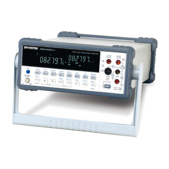
Digital Multimeter
GDM-8200 Series
USER MANUAL
GW INSTEK PART NO. 82DM-82550M01
ISO-9001 CERTIFIED MANUFACTURER
This manual contains proprietary information, which is protected by
copyrights. All rights are reserved. No part of this manual may be
photocopied, reproduced or translated to another language without
prior written consent of Good Will company.
The information in this manual was correct at the time of printing.
However, Good Will continues to improve products and reserves
the rights to change specification, equipment, and maintenance
procedures at any time without notice.
Good Will Instrument Co., Ltd.
No. 7-1, Jhongsing Rd., Tucheng City, Taipei County 236, Taiwan.
Advertisement
Chapters
Table of Contents

Subscribe to Our Youtube Channel
Related Manuals for GW Instek GDM-8251


Summary of Contents for GW Instek GDM-8251
-
Page 1: Digital Multimeter
Digital Multimeter GDM-8200 Series USER MANUAL GW INSTEK PART NO. 82DM-82550M01 This manual contains proprietary information, which is protected by copyrights. All rights are reserved. No part of this manual may be photocopied, reproduced or translated to another language without prior written consent of Good Will company. -
Page 2: Table Of Contents
Table of Contents GDM-8200 Series User Manual Digital Filter Setting .......... 62 Display Light Setting ......... 64 Table of Contents STORE/RECALL ............... 65 SAFETY INSTRUCTIONS ........... 5 Store Measurement Record ....... 65 Recall Measurement Record......66 Safety Symbols ............ 5 Recall Factory Installed Setup ...... -
Page 3: Safety Instructions
SAFETY INSTRUCTIONS GDM-8200 Series User Manual Safety Guidelines AFETY INSTRUCTIONS Make sure that the voltage input level does not exceed General Guideline • DC1000V/AC750V. Make sure the current input level does not exceed 10A. • CAUTION Do not place any heavy object on GDM-8200 series. This chapter contains important safety instructions that •... - Page 4 SAFETY INSTRUCTIONS GDM-8200 Series User Manual Disconnect the power cord before cleaning. Cleaning • Use a soft cloth dampened in a solution of mild Power cord for the United Kingdom GDM-8200 series • detergent and water. Do not spray any liquid into When using GDM-8200 series in the United Kingdom, make sure the power GDM-8200 series.
-
Page 5: Getting Started
GETTING STARTED GDM-8200 Series User Manual GDM-8200 Series Lineup ETTING STARTED GDM-8200 series consists of two models: GDM-8251 and GDM-8255. Both two models are identical except for the model name and Appearance This chapter describes GDM-8200 series in a nutshell, the meter count of the 1 display. -
Page 6: Gdm-8200 Series Characteristics
• Terminal High Voltage range: 1000V • High ACV frequency response: 100kHz • Terminal DCI/ACI 120000 meter count (GDM-8251) Features • Terminal 199999 meter count (GDM-8255) • Multi functions: ACV, DCV, ACA, DCA, 2W/4W R, • Hz, Continuity, Diode test, MAX/MIN, REL, dBm,... -
Page 7: Measurement Keys (Upper Row)
GETTING STARTED GDM-8200 Series User Manual Accepts ground (COM) line in all Starts the step measurement (page76) COM Terminal SHIFT → DCV measurements except the sense line in using the optional scanner. (STEP) 4W Resistance (page30). When the ACV key and the DCV key ACV + DCV are pressed together, they measure AC+DC Voltage (page24). -
Page 8: Measurement Keys (Lower Row)
GETTING STARTED GDM-8200 Series User Manual Measures Temperature (page37). Measures the Maximum or the °C/°F MX/MN Minimum value (page45). (Temperature) (MAX/ MIN) Selects the type of thermocouple SHIFT + °C/°F Selects the digital filter type for the SHIFT → used in the Temperature (SENSOR) signal sampling (page62). -
Page 9: Rear Panel Overview
GETTING STARTED GDM-8200 Series User Manual Accepts a digital I/O cable for the Digital I/O port Rear Panel Overview Hi/Lo limit test; DB-9 pin, female connector. GPIB Port Optional Item Power Cord For digital I/O details, see page86. (Optional) Slot x2 Socket Factory installed optional GPIB GPIB port... -
Page 10: Set Up
GETTING STARTED GDM-8200 Series User Manual Power Up Set Up 1. Connect the power Power up steps cord to the AC Tilt Stand Voltage input. Pull out the Tilt stand steps handle sideways and rotate it. Make sure the ground connector of the power cord is connected to a safety ground. -
Page 11: Basic Measurement
BASIC MEASUREMENT GDM-8200 Series User Manual Basic Measurement Overview ASIC MEASUREMENT Basic measurement refers to the eight types of Background measurements assigned to the upper row keys on the front panel. AC Voltage Measurement type ACV DC Voltage AC+DC Voltage ACV+DCV Overview Basic Measurement Overview ........22... -
Page 12: Ac/Dc/Ac+Dc Voltage Measurement
BASIC MEASUREMENT GDM-8200 Series User Manual 1. Press the Shift key followed by Selection step AC/DC/AC+DC Voltage Measurement the AUTO (RATE) key. The refresh rate switches to the next. 2. The refresh rate indicator shows 0 ~ 750V → → → Voltage type AC (true RMS) the current status. -
Page 13: Select Voltage Range
2.828 1.000 0.000 1.000 is unknown, select the highest range. PK-PK Selection list Range Resolution / Full scale @ slow rate Resolution Full scale Full scale (GDM-8251) (GDM-8255) Rectified Sine 1.414 0.435 0.900 1.000 (full wave) 1µV 120.000mV 199.999mV 100mV 10µV... -
Page 14: Ac/Dc/Ac+Dc Current Measurement
BASIC MEASUREMENT GDM-8200 Series User Manual Crest factor table AC/DC/AC+DC Current Measurement Crest factor is the ratio of the peak signal amplitude to the Background RMS value of the signal. It determines the accuracy of AC 0 ~ 10A Current type AC (true RMS) measurement. -
Page 15: 2W/4W Resistance Measurement
Selection list Range Resolution / Full scale @ slow rate Recommended for measuring sensitive Resolution Full scale Full scale resistances smaller than 1kΩ. (GDM-8251) (GDM-8255) For 2-wire resistance measurement, 1. Activate 0.1µA 12.0000mA 19.9999mA 10mA press the 2W/4W key once. -
Page 16: Diode Test
If the range is unknown, Press the key once. 1. Activate diode select the highest range. test Selection list Range Full scale @ slow rate 2. Diode mode display appears GDM-8251 GDM-8255 120.000Ω 199.999Ω 100Ω 1.2000kΩ 1.9999kΩ 1kΩ Indicates Diode test 12.0000kΩ 19.9999kΩ... -
Page 17: Continuity Test
BASIC MEASUREMENT GDM-8200 Series User Manual Set continuity threshold Continuity Test Continuity threshold defines the maximum resistance Background allowed in the DUT when testing the continuity. Continuity test checks that the resistance in the DUT is Background low enough to be considered continuous (of conductive 0 ~ 1000Ω, 1Ω... -
Page 18: Frequency/Period Measurement
BASIC MEASUREMENT GDM-8200 Series User Manual Select beeper setting Frequency/Period Measurement Beeper setting defines how GDM-8200 series notifies the Background continuity test result to the user. To measure Frequency, press the 1. Activate Hz/P key once. frequency/period Beeps when the test result is pass Beeper Pass measurement... -
Page 19: Temperature Measurement
BASIC MEASUREMENT GDM-8200 Series User Manual Select thermocouple type Temperature Measurement GDM-8200 series assumes that a certain type of Background thermocouple, which reads voltage fluctuation induced GDM-8200 series accepts thermocouple input and Background by temperature changes, is used to measure the calculates the temperature from the voltage fluctuation. -
Page 20: Set Reference Junction Temperature
BASIC MEASUREMENT GDM-8200 Series User Manual Set reference junction temperature When a thermocouple is connected to GDM-8200 series, Background DVANCED the temperature difference between the thermocouple lead and the GDM-8200 series input terminal should be taken into account and be cancelled; otherwise an MEASUREMENT erroneous temperature might be added. -
Page 21: Advanced Measurement
ADVANCED MEASUREMENT GDM-8200 Series User Manual 2. The refresh rate indicator shows → → → Advanced Measurement Overview the current status. Common attribute: reading indicator Advanced measurement mainly refers to the type of Background measurement which uses the result obtained by one of The reading indicator next to the 1st display flashes Background... -
Page 22: Dbm/Db Measurement
ADVANCED MEASUREMENT GDM-8200 Series User Manual To cancel the dBm measurement, Deactivate dBm dBm/dB Measurement press the Shift key followed by the measurement key, or simply activate another measurement. Applicable to (NOT applicable to ACV+DCV) Measure dB Using the ACV or DCV measurement result, GDM-8200 Background dB is defined as [dBm−dBmref]. -
Page 23: Max/Min Measurement
ADVANCED MEASUREMENT GDM-8200 Series User Manual Max/Min Measurement Relative Value Measurement Applicable to Applicable to Maximum and Minimum measurement stores the highest Relative measurement stores a value, typically the data at Background Background (maximum) or lowest (minimum) reading and shows it on the moment, as the reference. -
Page 24: Hold Measurement
ADVANCED MEASUREMENT GDM-8200 Series User Manual 3. Press the Enter key to confirm Hold Measurement the value, or the Exit key to cancel. The display switches to (confirm) measurement. Applicable to (cancel) To cancel the Relative measurement, Hold measurement retains the current measurement data Deactivate Background press the Shift key followed by the... -
Page 25: Compare Measurement
ADVANCED MEASUREMENT GDM-8200 Series User Manual Compare Measurement 3. Low limit setting Applicable to Compare measurement checks and updates if the Background Shows the low limit value 1st display measurement data stays between the upper (high) and Indicates low limit setting 2nd display lower (low) limit specified. -
Page 26: Math Measurement
ADVANCED MEASUREMENT GDM-8200 Series User Manual Math Measurement If the 2 display 5. Result High shows High, the result is above the High Applicable to limit. Math measurement runs three types of mathematical Digital I/O: FAIL Out (Pin 6) and HIGH Background operation, MX+B, 1/X, and percentage, based on the Limit FAIL Out (Pin 7) are activated. -
Page 27: Measure 1/X
ADVANCED MEASUREMENT GDM-8200 Series User Manual 2. Change the parameter using the Measure 1/X Up/Down key. 3. Press the ENTER key to Press the Shift key, the 2/4W (Math) 1. Activate 1/X confirm editing and move to key, the Down key twice. The 1/X offset setting. -
Page 28: Dual Display Measurement
ADVANCED MEASUREMENT GDM-8200 Series User Manual 1. Use the Left/Right key to move Dual Display Measurement the cursor (flashing point) between high/low setting, digits, and decimal point. You can use the 2nd display to show another item, thus Background viewing two different measurement results at once. The following table shows the available options. -
Page 29: System/Display Configuration
SYSTEM/DISPLAY CONFIGURATION GDM-8200 Series User Manual Refresh Rate Setting YSTEM/ ISPLAY Refresh rate defines how frequently GDM-8200 series Background captures and updates the measurement data. Faster refresh yields better accuracy but lower resolution. Slower CONFIGURATION refresh yields lower accuracy but higher resolution. Consider the trade-off when selecting the refresh rate. -
Page 30: Trigger Setting
SYSTEM/DISPLAY CONFIGURATION GDM-8200 Series User Manual Press the Shift key followed by the 1. Activate Trigger Setting TRIG key. The EXT indicator external trigger appears on the display. Manual/Automatic triggering GDM-8200 series triggers according to the refresh rate. Automatic See the previous page for refresh rate setting details. triggering Press the TRIG key to start 2. -
Page 31: Digital Filter Setting
SYSTEM/DISPLAY CONFIGURATION GDM-8200 Series User Manual Digital Filter Setting Overview 3. Move the flashing point (cursor) using the Left/Right key. Change the value using the The GDM-8200 series internal digital filter converts the Filter basic Up/Down key. analog input signal into digital format before passing it to internal circuits for further processing. -
Page 32: Display Light Setting
SYSTEM/DISPLAY CONFIGURATION GDM-8200 Series User Manual Filter setting Display Light Setting 1. Press the Shift key followed by Step the MX/MN (Filter) key. Display light setting adjusts the brightness of the display Background reading. Use level 3 or more (brighter) when working indoor;... -
Page 33: Store/Recall
STORE/RECALL GDM-8200 Series User Manual 3. Press the Enter key to confirm editing and to go back to the previous display. TORE/ ECALL For storing and recalling measurement results using the Indicates the measurement history is stored Scanner, see page68. Recall Measurement Record GDM-8200 series can recall the stored measurement Background... -
Page 34: Recall Factory Installed Setup
STORE/RECALL GDM-8200 Series User Manual Recall Factory Installed Setup CANNER (OPTIONAL) This function recalls the preset display setup. Background When powering GDM-8200 series Panel operation The scanner lets you effectively measure multiple up, press the AUTO key and the channels connected to a single GDM-8200 series. Power switch together. - Page 35 SCANNER (OPTIONAL) GDM-8200 Series User Manual Scanner Installation 3. The connection terminals appear. Configure scanner 1. Take off four screws from the bottom panel of the Open Scanner scanner. cover 2. Remove the top panel. 16 general purpose channels are available, 8 on the left Overview row, 8 on the right row.
-
Page 36: Select Channel Group
SCANNER (OPTIONAL) GDM-8200 Series User Manual Select Channel group Connect wire 2 groups, 16 channels each, are available for the scanner. Make sure the wires have at least the same Voltage and Background Wire selection Current capacity as the maximum ratings in the CH101 ~ 118 Group1 measurement. -
Page 37: Insert Scanner
SCANNER (OPTIONAL) GDM-8200 Series User Manual Take off the two screws on the slot corners to remove the Open GDM-8200 optional slot cover. Keep the screws for later reuse. series rear panel slot 4. Close the top cover and tighten the screw from the bottom. -
Page 38: Scanner Configuration Record
SCANNER (OPTIONAL) GDM-8200 Series User Manual Setup Scan Scanner Configuration Record Channel Wire color Measure type Note Overview Sets the scanned channel range, loop Scan type Simple count, and timer length. All channels have a common measurement item. In addition to the above Simple Scan Advanced setting, allows custom setting for each channel, such as measurement item,... -
Page 39: Setup Simple Scan
SCANNER (OPTIONAL) GDM-8200 Series User Manual Setup Simple Scan 1. Press the Shift key, the 2 Panel operation (MENU), the Left key twice. 6. Move the cursor to the channel The Scan menu appears. using the Left/Right key, and change the value using the Up/Down key. -
Page 40: Setup Advanced Scan
SCANNER (OPTIONAL) GDM-8200 Series User Manual Setup Advanced Scan 1. Press the Shift key, the 2 Panel operation (MENU), the Left key twice. 1 ~ 128 Range The Scan menu appears. 6. Move the cursor to the channel using the Left/Right key, and change the value using the Up/Down key. -
Page 41: Use External Trigger
SCANNER (OPTIONAL) GDM-8200 Series User Manual Use external trigger Run Scan GDM-8200 series uses the internal trigger by default. Background Using an external trigger allows customized triggering. Overview Connect the external trigger signal to the Digital I/O Signal Measures all specified channel range at Scan operation Scan port located on the rear panel. -
Page 42: Recall Scan/Step Result
SCANNER (OPTIONAL) GDM-8200 Series User Manual Recall Scan/Step result 3. Press the Down key. The channel selection appears. 1. After the Scan/Step is Panel operation completed, the data is stored internally. Press the Shift key followed by the ACI (Recall) key. 2. -
Page 43: Digital I/O
DIGITAL I/O GDM-8200 Series User Manual Digital I/O Terminal Configuration IGITAL I/O The digital I/O terminal outputs the result of Compare Background measurement to control external devices. By providing separate VCC for the terminal, the outputs can also be The rear panel Digital I/O terminal outputs the result of used as power source for TTL and CMOS logics. - Page 44 DIGITAL I/O GDM-8200 Series User Manual Application: Compare measurement 4. Set the low limit in the same way as in the high limit. Press the Applicable to ENTER key to confirm editing. The compare measurement Compare measurement checks and updates if the Background starts right away.
- Page 45 DIGITAL I/O GDM-8200 Series User Manual Application: External trigger GDM-8200 series uses the internal trigger by default, for Background EMOTE CONTROL example to count the frequency and the period. Using an external trigger allows customized triggering condition. Connect the external trigger signal to the Digital I/O Signal port located on the rear panel.
-
Page 46: Remote Control
REMOTE CONTROL GDM-8200 Series User Manual 4. Connect the USB cable to the Configure Interface rear panel terminal (upper K E Y C A L port). Overview Configure RS-232C interface USB 1.1 or 2.0, TypeA, female Interface type USB Host connector. - Page 47 REMOTE CONTROL GDM-8200 Series User Manual 4. Move the cursor using the Left/Right key. Change the value using the Up/Down key. Pin2 Pin2 GPIB address: 0 ~ 31 Pin3 Pin3 5. Press the ENTER key to confirm GPIB and address selection.
-
Page 48: Command Syntax
REMOTE CONTROL GDM-8200 Series User Manual Command Syntax Command Set The commands are partially compatible with IEEE488.2 (1992) and SCPI Commands are non-case sensitive. • (1994) standard. Commands are NON-case sensitive. Underline means a single space (dc_1→DC 1V). • When the parameter does not match the real value, the closest possible •... -
Page 49: Unit Command
REMOTE CONTROL GDM-8200 Series User Manual conf:curr:dc Sets measurement to DC Current and specifies range. sens:temp:rjun:sim? Returns temperature simulation value. Parameter: NR2, min, max sens:aver:tcon Selects digital filter type. Example: conf:curr:dc_10e-3 (DCI, 10mA range) Parameter: mov (moving), rep (repeating) Example: conf:curr:dc_min (DCI, minimum range) Example: sens:aver:tcon_mov (moving digital filter) conf:curr:ac Sets measurement to AC Current and specifies range. -
Page 50: Trigger Command
REMOTE CONTROL GDM-8200 Series User Manual calc:aver:aver? Returns average value stored. TRIGger command calc:aver:coun? Returns number of data count. calc:rel:ref Sets reference value in Relative value measurement. read? Returns 1 and 2 display value. Parameter: NR2, min, max val1? Returns 1 display value. -
Page 51: System Related Command
REMOTE CONTROL GDM-8200 Series User Manual IEEE 488.2 common command SYStem related command *cls Clears event status register (Output Queue, Operation Event Status, Questionable Event Status, Standard Event Status) syst:disp Turns display On or Off. Parameter: Boolean *ese? Returns ESER (Event Status Enable Register) contents. Example: disp_1 (display On) Example: 130 means ESER=10000010 syst:disp? - Page 52 REMOTE CONTROL GDM-8200 Series User Manual rout:scan? Returns currently scanned channels. Parameter: start channel followed by stop channel Secondary display: MEASure2 command meas2:volt:dc? Returns DC Voltage value on the 2 display. meas2:volt:ac? Returns AC Voltage value on the 2 display. meas2:curr:dc? Returns DC Current value on the 2 display.
-
Page 53: Appendix
Appendix GDM-8200 Series User Manual ppendix 2. Press the Down key followed by the Left key. The Self-test menu appears. System Info System Information ..........105 Fuse Replace AC source fuse ........107 Replacement 3. Press the Down key. The Replace input current fuse........ -
Page 54: Fuse Replacement
Appendix GDM-8200 Series User Manual Replace input current fuse Fuse Replacement 1. Press the Fuse holder. Step Replace AC source fuse 1. Take off the power cord and remove the fuse socket Step using a minus driver. 2. Replace the fuse in the holder. 2. -
Page 55: Specification
Specifications are for sine wave input > 5% of range • (*) Input > 450V only for 30sec, < 200V for 20 ~ 45Hz Note • Function Rate Full Scale Full Scale Rate Range Resolution (GDM-8251) (GDM-8255) 100.000mV 1μV 120.000mV 199.999mV 1.00000V 10μV 1.20000V 1.99999V 10.0000V 100μV 12.0000V... - Page 56 100.000V 1% + 100 0.2% + 100 1% + 100 3% + 200 • Full Scale Full Scale 750.00V(*) 1% + 100 0.2% + 100 1% + 100 3% + 200 Rate Range Resolution (GDM-8251) (GDM-8255) — 100.00mV 0.2% + 40 1.5% + 80 5% + 120 10.0000mA 0.1μA 12.0000mA 19.9999mA...
- Page 57 Max. Input: 500V DC or 500V rms AC • 600kHz ~ 800kHz 2.5V 0.05% + 3 Note Full Scale Full Scale Accuracy Rate Range Temperature (GDM-8251) (GDM-8255) reading%+digits 100.000Ω 120.000Ω 199.999Ω 0.05% + 8 1.00000kΩ 1.20000kΩ 1.99999kΩ 0.05% + 5 Sensor errors excluded from Temperature specification •...
-
Page 58: Ec Declaration Of Conformity
........... 67 2nd display digital filter Type of Product: Digital Multimeter command set........103 Model Number: GDM-8255 / GDM-8251 command set......98, 100 front panel key ........16 front panel key........16 measurement overview ..... 56 are herewith confirmed to comply with the requirements set out in the setting .......... -
Page 59: Index
INDEX GDM-8200 Series User Manual specification........114 command set........ 96, 97 external ..........59 command set........96 fuse front panel key ........14 front panel key ........15 front panel key........13 AC fuse replacement ......107 scanner configuration......70 scanner configuration......70 current fuse replacement ....108 setting ..........
Need help?
Do you have a question about the GDM-8251 and is the answer not in the manual?
Questions and answers