GW Instek GDM-8200A Series User Manual
Digital multimeter
Hide thumbs
Also See for GDM-8200A Series:
- User manual (122 pages) ,
- Quick user manual (7 pages) ,
- User manual (61 pages)

Related Manuals for GW Instek GDM-8200A Series


Summary of Contents for GW Instek GDM-8200A Series
-
Page 1: Digital Multimeter
Digital Multimeter GDM-8200A Series USER MANUAL GW INSTEK PART NO. 82DM-8255AEA1 ISO-9001 CERTIFIED MANUFACTURER... - Page 2 This manual contains proprietary information, which is protected by copyrights. All rights are reserved. No part of this manual may be photocopied, reproduced or translated to another language without prior written consent of Good Will company. The information in this manual was correct at the time of printing. However, Good Will continues to improve products and reserves the right to change specifications, equipment, and maintenance procedures at any time without notice.
-
Page 3: Table Of Contents
Safety Symbols ............ 5 Safety Guidelines ..........6 GETTING STARTED ............9 GDM-8200A Series Lineup ........ 10 GDM-8200A Series Characteristics ....11 Front Panel Overview ........12 Rear Panel Overview ......... 17 ... - Page 4 GDM-8200A Series User Manual Digital Filter Setting .......... 62 Display Setting ..........64 STORE/RECALL ............... 66 Store Measurement Record ....... 67 Recall Measurement Record ......68 Save Instrument Settings ........69 Recall Instrument Settings ........ 70 ...
-
Page 5: Safety Instructions
Warning: Identifies conditions or practices that could result in injury or loss of life. WARNING Caution: Identifies conditions or practices that could result in damage to the GDM-8200A series or to other CAUTION properties. DANGER High Voltage Attention Refer to the Manual... -
Page 6: Safety Guidelines
Do not disassemble the GDM-8200A series unless you are qualified as service personnel. (Note) EN 61010-1:2001 specifies the measurement categories and their requirements as follows. The GDM-8200A series fall under category I or II. Measurement category IV is for measurement performed at the ... - Page 7 (full accuracy) (Note) EN 61010-1:2001 specifies the pollution degrees and their requirements as follows. the GDM-8200A series falls under degree Pollution refers to “addition of foreign matter, solid, liquid, or gaseous (ionized gases), that may produce a reduction of dielectric strength or surface resistivity”.
- Page 8 GDM-8200A Series User Manual Power cord for the United Kingdom When using the GDM-8200A series in the United Kingdom, make sure the power cord meets the following safety instructions. NOTE: This lead / appliance must only be wired by competent persons...
-
Page 9: Getting Started
GETTING STARTED ETTING STARTED This chapter describes the GDM-8200A series in a nutshell, including its main features, package contents, and front / rear / display panel introduction. After going through the overview, follow the Power-up sequence and Functionality check section to properly setup the GDM-8200A series. -
Page 10: Gdm-8200A Series Lineup
GDM-8200A Series User Manual GDM-8200A Series Lineup The GDM-8200A series consists of two models: GDM-8251A and GDM-8255A. Both two models are identical except for the model name and Appearance the meter count of the 1 display. display meter: 120,000 counts... -
Page 11: Gdm-8200A Series Characteristics
GETTING STARTED GDM-8200A Series Characteristics The GDM-8200A series are portable, dual-display digital multimeters suitable for wide range of applications, such as production testing, research, and field verification. High DCV accuracy: 0.012% Performance High current range: 10A High Voltage range: 1000V ... -
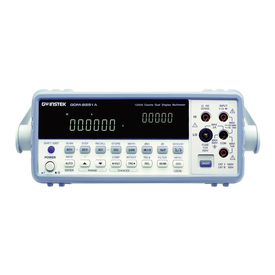
Page 12: Front Panel Overview
GDM-8200A Series User Manual Front Panel Overview Main Measurement 4W Ohm Fuse Display Terminal Main Terminal Terminal DCI/ACI Terminal Power Switch Output On/Off key Turns On or Off the main power. Power Switch For power up sequence, see page20. Shows measurement results and parameters. -
Page 13: Measurement Keys (Upper Row)
GETTING STARTED Accepts ground (COM) line in all COM Terminal measurements except the sense line in 4W Resistance (page30). Accepts input in all measurements Voltage/ 2W Ω / except for DC/AC Current and 4W (Diode) Resistance sense line. Terminal Accepts DC/AC Current input. Current Terminal For DCI/ACI details, see page28. - Page 14 GDM-8200A Series User Manual Starts the step measurement (page79) SHIFT → DCV using the optional scanner. (STEP) When the ACV key and the DCV key ACV + DCV are pressed together, they measure AC+DC Voltage (page24). Measures AC Current (page28).
-
Page 15: Measurement Keys (Lower Row)
GETTING STARTED Measures Temperature (page37). °C/°F (Temperature) Selects the type of thermocouple SHIFT + °C/°F used in the Temperature (SENSOR) measurement (page38). Measurement keys (Lower row) As the AUTO key, selects the AUTO/ENTER measurement range automatically. As the ENTER key, confirms the entered value. - Page 16 GDM-8200A Series User Manual Measures the Maximum or the MX/MN Minimum value (page45). (MAX/ MIN) Selects the digital filter type for the SHIFT → signal sampling (page62). MX/MN (FILTER) As the 2 key, selects the (Display) / measurement item on the 2...
-
Page 17: Rear Panel Overview
GETTING STARTED Rear Panel Overview Optional Item Power Cord Slot x2 Socket Digital I/O CAL Key RS-232C Fuse USB Device Port Port Port T3.15A/250V Port Accepts the power cord. AC Power Cord Socket 100–240V, 50–60Hz. For power on sequence, see page20. Holds the main fuse: T3.15A 250V, Fuse Socket 20VA. - Page 18 GDM-8200A Series User Manual Accepts a digital I/O cable for the Digital I/O port Hi/Lo limit test; DB-9 pin, female connector. For digital I/O details, see page90. Accepts up to two optional scanner modules. 16 Optional slot x2 channels are available per scanner. When two modules are used, maximum 32 channels are available.
-
Page 19: Set Up
GETTING STARTED Set Up Tilt Stand Pull out the Tilt stand steps handle sideways and rotate it. Place the unit horizontally, Or in the tilt stand position. Place the handle vertically for hand carry. -
Page 20: Power Up
GDM-8200A Series User Manual Power Up 1. Connect the power Power up steps cord to the AC Voltage input. Make sure the ground connector of the power cord is connected to a safety ground. This will affect the Note measurement accuracy. -
Page 21: Basic Measurement
BASIC MEASUREMENT ASIC MEASUREMENT Overview Basic Measurement Overview ........ 22 Common attribute: refresh rate ......22 Common attribute: reading indicator ..... 23 Common attribute: manual/automatic triggering .. 23 Voltage AC/DC/AC+DC Voltage Measurement ....24 Select Voltage range ..........25 Voltage conversion table ........26 Crest factor table ............ -
Page 22: Basic Measurement Overview
GDM-8200A Series User Manual Basic Measurement Overview Basic measurement refers to the eight types of Background measurements assigned to the upper row keys on the front panel. AC Voltage Measurement type ACV DC Voltage AC+DC Voltage ACV+DCV AC Current DC Current... -
Page 23: Common Attribute: Reading Indicator
The reading indicator next to the 1st display flashes Background according to the refresh rate setting. Common attribute: manual/automatic triggering The GDM-8200A series triggers according to the refresh Automatic rate. See the previous page for refresh rate setting details. triggering (default) -
Page 24: Ac/Dc/Ac+Dc Voltage Measurement
GDM-8200A Series User Manual AC/DC/AC+DC Voltage Measurement 0 ~ 750V Voltage type 0 ~ 1000V 0 ~ 1000V AC+DC (AC = true RMS) Press the ACV (AC Voltage) key or 1. Activate ACV/ DCV (DC Voltage) key. For AC+DC Voltage, press the ACV key and the DCV key together. -
Page 25: Select Voltage Range
BASIC MEASUREMENT Select Voltage range To turn the automatic range selection Auto range On/Off, press the AUTO key. Press the Up or the Down key to select Manual range the range. AUTO indicator turns Off automatically. If the appropriate range is unknown, select the highest range. -
Page 26: Voltage Conversion Table
GDM-8200A Series User Manual Voltage conversion table This table shows the relationship between AC, DC, and AC+DC reading in various waveforms. Waveform Peak to Peak AC + DC (True RMS) (True RMS) Sine 2.828 1.000 0.000 1.000 PK-PK Rectified Sine 1.414... -
Page 27: Crest Factor Table
BASIC MEASUREMENT Crest factor table Crest factor is the ratio of the peak signal amplitude to the Background RMS value of the signal. It determines the accuracy of AC measurement. If the crest factor is less than 3.0, voltage measurement will not result in error due to dynamic range limitations at full scale. -
Page 28: Ac/Dc/Ac+Dc Current Measurement
GDM-8200A Series User Manual AC/DC/AC+DC Current Measurement 0 ~ 10A Current type 0 ~ 10A 0 ~ 10A AC+DC (AC = true RMS) Press the ACI (AC Current) key or 1. Activate ACV/ the DCI (DC Current) key. For AC+DC Current, press the ACI key and the DCI key together. -
Page 29: Select Current Range
BASIC MEASUREMENT Select Current range To turn the automatic range selection Auto range On/Off, press the AUTO key. Press the Up or the Down key to select Manual range the range. AUTO indicator turns Off automatically. If the appropriate range is unknown, select the highest range. -
Page 30: 2W/4W Resistance Measurement
GDM-8200A Series User Manual 2W/4W Resistance Measurement Uses the standard V-COM ports. Measurement 2-wire Recommended for measuring resistances type larger than 1kΩ. Compensates the test lead effect using the 4-wire 4W compensation ports, in addition to the standard V-COM ports. -
Page 31: Resistance 2W/4W Resistance Measurement
BASIC MEASUREMENT Select Resistance range To turn the automatic range selection Auto range On/Off, press the AUTO key. Press the Up or the Down key to select Manual range the range. AUTO indicator turns Off automatically. If the range is unknown, select the highest range. -
Page 32: Diode Test
GDM-8200A Series User Manual Diode Test Diode test checks the forward bias characteristics of a Background diode by running a constant forward bias current, approx. 0.5mA, through the DUT. Press the key once. 1. Activate diode test 2. Diode mode... -
Page 33: Continuity Test
BASIC MEASUREMENT Continuity Test Continuity test checks that the resistance in the DUT is Background low enough to be considered continuous (of conductive nature). Press the key twice. 1. Activate continuity test 2. Continuity mode display appears + Ω Indicates Continuity test CONT 2nd display shows the title Connect the test lead between the Ω... -
Page 34: Set Continuity Threshold
GDM-8200A Series User Manual Set continuity threshold Continuity threshold defines the maximum resistance Background allowed in the DUT when testing the continuity. 0 ~ 1000Ω, 1Ω resolution, 10Ω default Threshold Range 1. Press the Shift key, the 2ND key, 1. Activate the Right key. -
Page 35: Select Beeper Setting
BASIC MEASUREMENT Select beeper setting Beeper setting defines how the GDM-8200A series Background notifies the continuity test result to the user. Beeps when the test result is pass Beeper Pass parameter Beeps when the test result is fail Fail Beep function is turned Off 1. -
Page 36: Frequency/Period Measurement
GDM-8200A Series User Manual Frequency/Period Measurement To measure Frequency, press the 1. Activate Hz/P key once. frequency/period measurement To measure Period, press the Hz/P key twice. 2. Frequency (Period) mode display appears Hz (S) Indicates Frequency (period) measurement FREQ 2nd display shows the title... -
Page 37: Temperature Measurement
BASIC MEASUREMENT Temperature Measurement The GDM-8200A series accepts thermocouple input and Background calculates the temperature from the voltage fluctuation. Thermocouple type and reference junction temperature are also being considered. For Celsius unit, press the °C/°F key 1. Activate once. temperature measurement For Fahrenheit unit, press the °C/°F... -
Page 38: Select Thermocouple Type
GDM-8200A Series User Manual Select thermocouple type The GDM-8200A series assumes that a certain type of Background thermocouple, which reads voltage fluctuation induced by temperature changes, is used to measure the temperature. Parameter Type Range Resolution 0 ~ +300°C 0.01°C 0 ~ +300°C... -
Page 39: Set Reference Junction Temperature
When a thermocouple is connected to the GDM-8200A Background series, the temperature difference between the thermocouple lead and the the GDM-8200A series input terminal should be taken into account and be cancelled; otherwise an erroneous temperature might be added. Type... -
Page 40: Advanced Measurement
GDM-8200A Series User Manual DVANCED MEASUREMENT Overview Advanced Measurement Overview ......41 Common attribute: refresh rate ......41 Common attribute: reading indicator ..... 42 Common attribute: manual/automatic triggering .. 42 dBm/dB dBm/dB Measurement ........... 43 Measure dBm ............43 Measure dB ............44 Max/Min Max/Min Measurement ......... -
Page 41: Advanced Measurement Overview
ADVANCED MEASUREMENT Advanced Measurement Overview Advanced measurement mainly refers to the type of Background measurement which uses the result obtained by one of the basic measurements: ACV, DCV, ACI, DCI, 2/4W, Diode/Continuity, Frequency/Period, and Temperature. Advanced Basic Measurement Measurement AC/DCV AC/DCI 2/4W Hz/P °C/°F... -
Page 42: Common Attribute: Reading Indicator
When there is no captured data, the reading indicator When no data is flashes once per two seconds (slower than the normal captured refresh rate), showing the GDM-8200A series is in the waiting mode. Common attribute: manual/automatic triggering The GDM-8200A series triggers according to the refresh Automatic rate. -
Page 43: Dbm/Db Measurement
Applicable to (NOT applicable to ACV+DCV) Using the ACV or DCV measurement result, the Background GDM-8200A series calculates the dB or dBm value based on a reference resistance value in the following way. 10 x log (1000 x Vreading / Rref) dBm –... -
Page 44: Measure Db
Measure dB dB is defined as [dBm−dBmref]. When the dB Background measurement is activated, the GDM-8200A series calculates the dBm using the reading at the first moment and stores it as dBmref. Press the Shift key followed by the Activate dB Hz/P key. -
Page 45: Max/Min Measurement
ADVANCED MEASUREMENT Max/Min Measurement Applicable to Maximum and Minimum measurement stores the highest Background (maximum) or lowest (minimum) reading and shows it on the 2nd display. For Max measurement, press the MX/MN 1. Activate key once. Max/Min For Min measurement, press the MX/MN key twice. -
Page 46: Relative Value Measurement
GDM-8200A Series User Manual Relative Value Measurement Applicable to Relative measurement stores a value, typically the data at Background the moment, as the reference. The following measurement is shown as the delta between the reference. Press the REL key. The 1. - Page 47 ADVANCED MEASUREMENT 3. Press the Enter key to confirm the value, or the Exit key to cancel. The display switches to (confirm) measurement. (cancel) To cancel the Relative measurement, Deactivate press the Shift key followed by the Relative REL key, or simply activate another measurement measurement.
-
Page 48: Hold Measurement
GDM-8200A Series User Manual Hold Measurement Applicable to Hold measurement retains the current measurement data Background and updates it only when the reading fluctuates more than the threshold setting as the percentage of the retained data. Press the HOLD key. -
Page 49: Compare Measurement
ADVANCED MEASUREMENT Compare Measurement Applicable to Compare measurement checks and updates if the Background measurement data stays between the upper (high) and lower (low) limit specified. Press the Shift key, then the HOLD 1. Activate (Comp) key. Compare measurement 2. High limit setting Shows the high limit value 1st display... - Page 50 GDM-8200A Series User Manual 3. Low limit setting Shows the low limit value 1st display Indicates low limit setting 2nd display 1. Use the Left/Right key to move the cursor (flashing point) between high/low setting, digits, and decimal point. 2. Change the parameter using the Up/Down key.
- Page 51 ADVANCED MEASUREMENT If the 2 display 5. Result High shows High, the result is above the High limit. Digital I/O: FAIL Out (Pin 6) and HIGH Limit FAIL Out (Pin 7) are activated. If the 2 display shows Low, the result is below the Low limit.
-
Page 52: Math Measurement
GDM-8200A Series User Manual Math Measurement Applicable to Math measurement runs three types of mathematical Background operation, MX+B, 1/X, and percentage, based on the other measurement results. Multiplies the reading (X) by the factor (M) Math type MX+B and adds/subtracts offset (B). - Page 53 ADVANCED MEASUREMENT 2. Change the parameter using the Up/Down key. 3. Press the ENTER key to confirm editing and move to offset setting. 3. Set the offset Shows the offset (B) 1st display Indicates MX+B (The letter B flashes) 2nd display 1.
-
Page 54: Measure 1/X
GDM-8200A Series User Manual Measure 1/X Press the Shift key, the 2/4W (Math) 1. Activate 1/X key, the Down key twice. The 1/X setting appears. Press the ENTER key to view the 1/X measurement result. Shows the 1/X value 1st display... -
Page 55: Dual Display Measurement
ADVANCED MEASUREMENT 1. Use the Left/Right key to move the cursor (flashing point) between high/low setting, digits, and decimal point. 2. Change the parameter using the Up/Down key. 3. Press the ENTER key to confirm editing and move to offset setting. 4. - Page 56 GDM-8200A Series User Manual ● ● ● ● ● 2W* (see Note) ● ● ● ● ● Hz/P — — — — — °C/°F — — — — — In the dual display mode, the resistance needs to be Note ...
-
Page 57: System/Display Configuration
SYSTEM/DISPLAY CONFIGURATION YSTEM/ ISPLAY CONFIGURATION Refresh Rate Refresh Rate Setting ..........58 Trigger Manual/Automatic triggering ......... 59 Use external trigger ..........59 Set trigger delay ............. 60 Digital Filter Overview ..............62 Filter setting ............63 Display Display Setting ............64 Display on/off setting (+ key lock) ...... -
Page 58: Refresh Rate Setting
GDM-8200A Series User Manual Refresh Rate Setting Refresh rate defines how frequently the GDM-8200A Background series captures and updates the measurement data. Faster refresh rate yields lower accuracy and resolution. Slower refresh rate yields higher accuracy and resolution. Consider the trade-off when selecting the refresh rate. -
Page 59: Trigger Setting
SYSTEM/DISPLAY CONFIGURATION Trigger Setting Manual/Automatic triggering The GDM-8200A series triggers according to the refresh Automatic rate. See the previous page for refresh rate setting details. triggering (default) Press the TRIG key to trigger Manual measurement manually. triggering Use external trigger... -
Page 60: Set Trigger Delay
GDM-8200A Series User Manual Press the Shift key followed by the 1. Activate TRIG key. The EXT indicator external trigger appears on the display. Press the TRIG key to start 2. Start trigger triggering manually. The indicator turns On. The reading indicator stays On before triggering. - Page 61 SYSTEM/DISPLAY CONFIGURATION 3. Move the flashing point (cursor) using the Left/Right key. Change the value using the Up/Down key. 4. Press the ENTER key to confirm editing and press the EXIT key. The display goes back to previous mode. 1 ~ 1000ms, 1ms resolution Range...
-
Page 62: Digital Filter Setting
GDM-8200A Series User Manual Digital Filter Setting Overview The GDM-8200A series internal digital filter converts the Filter basic analog input signal into digital format before passing it to internal circuits for processing. The filter affects the amount of noise included in the measurement result. -
Page 63: Filter Setting
SYSTEM/DISPLAY CONFIGURATION Filter setting 1. Press the Shift key followed by Step the MX/MN (Filter) key. Shows the filter count 1st display Shows the filter type (flashing) 2nd display 2. Select the filter type using the Up/Down key. 3. Move the cursor to filter count using the Left/Right key. -
Page 64: Display Setting
GDM-8200A Series User Manual Display Setting Display light setting Display light setting adjusts the brightness of the display Background reading. Use level 3 or more (brighter) when working indoor; use level 2 or 1 (darker) when working outdoor under the sun. -
Page 65: Display On/Off Setting (+ Key Lock)
SYSTEM/DISPLAY CONFIGURATION Display on/off setting (+ key lock) The display can be turned off when not used for a long Background time. Note that when this function is used, the panel keys are also locked except for the Output On/Off key. The display is turned on by default. -
Page 66: Store/Recall
GDM-8200A Series User Manual TORE/ ECALL For storing and recalling measurement results using the Scanner, see page71. Store Measurement Record ....... 67 Recall Measurement Record ......68 Save Instrument Settings ........69 Recall Instrument Settings ........ 70... -
Page 67: Store Measurement Record
STORE/RECALL Store Measurement Record The GDM-8200A series can store the measurement Background history which can be recalled later for observation and analysis as in Maximum, Minimum, and Average value. 1 ~ 9999 Data count Store/recall measurement history is not applicable to... -
Page 68: Recall Measurement Record
GDM-8200A Series User Manual Recall Measurement Record The GDM-8200A series can recall the stored Background measurement history for observation and analysis as in Maximum, Minimum, and Average value. Store/recall measurement history is not applicable to Not applicable to Diode/Continuity test... -
Page 69: Save Instrument Settings
STORE/RECALL Save Instrument Settings The GDM-8200A series can save up to ten instrument Background settings. The settings can save the state, function, I/O and range. Upon powering up, the current instrument setting is displayed. Press the Shift key, the 2ND key, Set Instrument Down and then Left twice. -
Page 70: Recall Instrument Settings
GDM-8200A Series User Manual Recall Instrument Settings The Recall function to enables saved settings to be Background recalled power up. Press the Shift key, then the 2ND Set Instrument (Menu) key, Down and Left once. Setting The Recall menu appears. -
Page 71: Scanner (Optional)
SCANNER (OPTIONAL) CANNER (OPTIONAL) The optional scanner GDM-SC1 lets you effectively measure multiple channels connected to a single the GDM-8200A series. Installation GDM-SC1 Scanner Specifications ......72 Configure scanner ..........72 Select Channel group and enable scanner....74 Connect wire ............75 Insert scanner ............ -
Page 72: Gdm-Sc1 Scanner Specifications
GDM-8200A Series User Manual GDM-SC1 Scanner Specifications 16 pairs 2A (ch17, ch18) 2-wire channel Maximum current 8 pairs 2/4 wire 4-wire channel Resistance N/A (internal) Single wire channel Cold junction 250V Screw terminal Maximum voltage Connection Scanner Installation Configure scanner 1. - Page 73 SCANNER (OPTIONAL) 3. The connection terminals appear. 16 general purpose channels are available, 8 on the left Overview row, 8 on the right row. Current (ACI, DCI) measurement uses 2 extra channels. All channels are fully isolated (Hi and Lo). Refer to the below table for measurement and test line Scan/Step connection.
-
Page 74: Select Channel Group And Enable Scanner
GDM-8200A Series User Manual Select Channel group and enable scanner 2 groups, 16 channels each, are available for the scanner. Background CH101 ~ 118 Group1 CH201 ~ 218 Group2 Set the jumper J8 in the center of the board accordingly. -
Page 75: Connect Wire
SCANNER (OPTIONAL) Connect wire Make sure the wires have at least the same Voltage and Wire selection Current capacity as the maximum ratings in the measurement. 1. Turn the screw left (loose) using the screw driver and Connection insert the wire. Turn the screw right (tight) and secure the connection. -
Page 76: Insert Scanner
4. Close the top cover and tighten the screw from the bottom. Print out the configuration record list on page78, fill in Configuration the details, and keep it with the GDM-8200A series. Record Insert scanner Turn the Power Off and take off the power cord. - Page 77 SCANNER (OPTIONAL) Take off the two screws on the slot corners to remove the Open the optional slot cover. Keep the screws for later reuse. GDM-8200A series rear panel slot Insert the scanner (already configured according to the Insert the procedures on page72) to either of the two slots, upper or scanner lower.
-
Page 78: Scanner Configuration Record
GDM-8200A Series User Manual Scanner Configuration Record Channel Wire color Measure type Note CH10 CH11 CH12 CH13 CH14 CH15 CH16 CH17 CH18 CARD INPUT H CARD SENSE H AMPS... -
Page 79: Setup Scan
(Continuous) of loop count. Then it goes into the idle mode. The GDM-8200A series stays in the idle External mode by default. The trigger timing is (Manual) manually controlled by the user from the front panel (TRIG key). -
Page 80: Setup Simple Scan
GDM-8200A Series User Manual Setup Simple Scan 1. Press the Shift key, the 2 Panel operation (MENU), the Left key. The Scan menu appears. 2. Press the Down key. The Simple Scan menu appears. 3. Press the Down key again. The Starting (Minimum) channel setting appears. - Page 81 SCANNER (OPTIONAL) 6. Move the cursor to the channel using the Left/Right key, and change the value using the Up/Down key. 101 ~ 118, 201 ~ 218 (must be the same Range or bigger than the Start (Min) channel) 7. When finished, press the ENTER key.
-
Page 82: Setup Advanced Scan
GDM-8200A Series User Manual Setup Advanced Scan 1. Press the Shift key, the 2 Panel operation (MENU), the Left key. The Scan menu appears. 2. Press the Down key followed by the Right key. The Advanced Scan menu appears. 3. Press the Down key. The Starting (Minimum) channel setting appears. - Page 83 SCANNER (OPTIONAL) 6. Move the cursor to the channel using the Left/Right key, and change the value using the Up/Down key. 101 ~ 118, 201 ~ 218 (must be the same Range or bigger than the Start (Min) channel) 7. When finished, press the ENTER key.
- Page 84 GDM-8200A Series User Manual 13. Set the measurement condition. To select measurement item, C/ F press the target key. To select Auto range, press the AUTO key. To manually select the range, press the Up/Down key. 14. When finished, press the Right key to confirm edit and to move to the next channel.
-
Page 85: Use External Trigger
SCANNER (OPTIONAL) Use external trigger The GDM-8200A series uses the internal trigger by Background default. Using an external trigger allows customized triggering. Connect the external trigger signal to the Digital I/O Signal port located on the rear panel. connection DB-9, female... -
Page 86: Run Scan
GDM-8200A Series User Manual Run Scan Overview Measures all specified channel range at Scan operation Scan each trigger event. Timer setting (page80) type applies between each scan. Measures a single channel in the specified Step range at each trigger event. Timer setting (page80) applies between each channel. -
Page 87: Recall Scan/Step Result
SCANNER (OPTIONAL) Recall Scan/Step result 1. After the Scan/Step is Panel operation completed, the data is stored internally. Press the Shift key followed by the ACI (Recall) key. 2. The first channel appears. (example: channel 101) 3. To view the Max/Min/Average data, press the Left key. - Page 88 GDM-8200A Series User Manual 3. Press the Down key. The channel selection appears. 4. Move the cursor to the channel using the Left/Right key, and change the value using the Up/Down key. 5. When finished, press the ENTER key. The Monitoring...
-
Page 89: Digital I/O
DIGITAL I/O IGITAL I/O The rear panel Digital I/O terminal outputs the result of Compare measurement to external devices. Terminal Digital I/O Terminal Configuration ......90 configuration Application Application: Compare measurement ...... 91 Application: External trigger ........93... -
Page 90: Digital I/O Terminal Configuration
GDM-8200A Series User Manual Digital I/O Terminal Configuration The digital I/O terminal outputs the result of Compare Background measurement to control external devices. By providing separate VCC for the terminal, the outputs can also be used as power source for TTL and CMOS logics. - Page 91 DIGITAL I/O Application: Compare measurement Applicable to Compare measurement checks and updates if the Background measurement data stays between the upper (high) and lower (low) limit specified. Press the Shift key, then the HOLD 1. Activate (Comp) key. Compare measurement 2.
- Page 92 GDM-8200A Series User Manual Set the low limit in the same way as in the high limit. Press the ENTER key to confirm editing. The compare measurement starts right away. 4. Compare measurement appears Indicates Compare mode COMP Shows the compare measurement result: display Pass, High, or Low.
- Page 93 DIGITAL I/O Application: External trigger The GDM-8200A series uses the internal trigger by Background default, for example to count the frequency and the period. Using an external trigger allows customized triggering condition. Connect the external trigger signal to the Digital I/O Signal port located on the rear panel.
-
Page 94: Remote Control
GDM-8200A Series User Manual EMOTE CONTROL Interface Overview ..............95 Configure USB interface ......... 95 Configure RS-232C interface ........96 Command Syntax Command Syntax ........... 98 Command Set CONFigure command ..........99 SENSe command ..........100 UNIT command ........... 101 TRIGger command .......... -
Page 95: Configure Interface
REMOTE CONTROL Configure Interface Overview USB 1.1 or 2.0, TypeA, female Interface type USB Device connector. D-sub 9 pin, male connector. Baud RS-232C rate: 115200/57600/38400/19200/ 9600. In order to switch back to the Return to Local Local control mode (front panel control mode operation), press the LOCAL key. -
Page 96: Configure Rs-232C Interface
GDM-8200A Series User Manual 5. Press the ENTER key to confirm USB selection. 6. Connect the USB cable to the rear panel terminal (upper K E Y C A L port). Configure RS-232C interface Configuration step 1. Press the Shift key, the 2ND (Menu) key, the Right key twice. - Page 97 REMOTE CONTROL RS-232C pin 9 8 7 6 Pin 2: RxD assignment Pin 3: TxD Pin 5: GND Pin 1, 4, 6 ~ 9: No Connection 5 4 3 2 1 Null-modem connection, in which transmit (TxD) and PC – GDM receive (RxD) lines are cross-linked, is required.
-
Page 98: Command Syntax
Floating point number: 4.5e-1, 8.5e+1,... The GDM-8200A series automatically min, max translates to Minimum (min) or Maximum (max) value available. The GDM-8200A series automatically translates the Automatic command parameter into the closest available value. parameter range selection conf:volt:dc_1 (Sets the measurement Example 1 item to DC Voltage and the range to 1V). -
Page 99: Command Set
REMOTE CONTROL Command Set Commands are non-case sensitive. Underline means a single space (dc_1→DC 1V). When the parameter does not match the real value, the closest possible option is automatically selected (dc_2 [DC 2V range]→DC 10V) CONFigure command conf:volt:dc Sets measurement to DC Voltage and specifies range. -
Page 100: Sense Command
GDM-8200A Series User Manual conf:per Sets measurement to Period and specifies range. conf:cont Sets measurement to Continuity. conf:diod Sets measurement to Diode. conf:temp Sets measurement to Temperature. conf:stat:func? Returns function of 1 display. Parameter: 1 (DCV), 2 (ACV), 3 (DCA-10A), 4 (ACA-10A), 5... -
Page 101: Unit Command
REMOTE CONTROL sens:aver:tcon Selects digital filter type. Parameter: mov (moving), rep (repeating) Example: sens:aver:tcon_mov (moving digital filter) sens:aver:tcon? Returns digital filter type. Parameter: MOV (moving), REP (repeating) sens:aver:coun Sets digital filter count. Parameter: 2 ~ 100 Example: sens:aver:coun_100 (filter count 100) sens:aver:coun? Returns current digital filter count. - Page 102 GDM-8200A Series User Manual calc:aver:min? Returns minimum value stored. calc:aver:max? Returns maximum value stored. calc:aver:aver? Returns average value stored. calc:aver:coun? Returns number of data count. calc:rel:ref Sets reference value in Relative value measurement. Parameter: NR2, min, max Example: calc:rel:ref_1.0 (reference value set to 1.0) calc:rel:ref? Returns reference value in Relative value measurement.
-
Page 103: Trigger Command
REMOTE CONTROL calc:math:perc Sets target value in Math measurement. Parameter: NR2 Example: calc:math:perc_50 (target set to 50) calc:hold:ref Set percentage of Hold function. Parameter: 0 to 99, min, max calc:hold:ref? Return percentage of Hold function. Parameter: 0 to 99 TRIGger command read? Returns 1 and 2... -
Page 104: System Related Command
GDM-8200A Series User Manual trac:cle Clears buffer contents. SYStem related command syst:disp Turns display On or Off. Parameter: Boolean Example: disp_1 (display On) syst:disp? Returns display status, On of Off. Parameter: Boolean syst:beep:stat Select beep mode. Parameter: 0 (Off), 1 (Pass), 2 (Fail) -
Page 105: Route Command
Sets SRER contents. Example: *SRE 7 SRER=00000111 *stb? Returns SBR (Status Byte Register) contents. Example: 81 means SBR=01010001 *trg Manually triggers the GDM-8200A series. ROUTe command rout:clos Close specified scanner channel. Parameter: NR1, min, max Example: rout:clos_102 (close channel102 rout:open:all Opens all scanner channels. -
Page 106: Configure2 Command
GDM-8200A Series User Manual rout:chan Configure channel in advanced mode. Parameter: Channel, Function, Range, Auto Range Example: rout:chan 101, 1, 2, 0 (Channel 101, Function 1 (DCV), Range 2 (DCV 1V), Disable Auto Range) rout:chan? Return channel configurations in advanced mode. - Page 107 REMOTE CONTROL conf2:freq Configure 2 display to Frequency. conf2:per Configure 2 display to Period. conf2:temp Configure 2 display to Temperature. conf2:off Turn off the dual display mode (2 display is off) conf2:stat:func? Returns function of 2 display. Parameter: 1 (DCV), 2 (ACV), 3 (DCA-10A), 4 (ACA-10A), 5 (DCA-mA), 6 (ACA-mA), 7 (2WR), 8 (Freq), 9 (TempC), 10 (AC+DCA-10A), 11 (AC+DCV), 12 (AC+DCA-mA), 13 (Diode), 14 (Period), 15 (TempF), 16 (4WR), 17 (Cont.)
-
Page 108: Faq
● What is the Output key used for? ● I pressed the EXIT key but cannot get out of Scanner mode. ● The GDM-8200A series performance does not match the specifications. What is the Output key used for? The Output key is used for turning the display output on or off. -
Page 109: Appendix
APPENDIX PPENDIX System Info Firmware Version ..........109 Fuse Replace AC source fuse ........111 Replacement Replace input current fuse ........112 Specifications General ..............113 Reading rates (readings/sec)........113 DC Voltage ............113 AC Voltage ............114 DC Current ............115 AC Current ............116 2W Resistance ............117 4W Resistance ............117 Diode/Continuity ..........118 Frequency .............118... -
Page 110: Firmware Version
GDM-8200A Series User Manual Firmware Version Firmware version is available for viewing system Background information. Shows the GDM-8200A series Firmware firmware version number. version 1. Press the Shift key followed by View firmware the 2ND (Menu) key. The version system menu appears. -
Page 111: Fuse Replacement
APPENDIX Fuse Replacement Replace AC source fuse 1. Take off the power cord and remove the fuse socket Step using a minus driver. 2. Replace the fuse in the holder. T3.15A, 250V Rating... -
Page 112: Replacement Replace Input Current Fuse
GDM-8200A Series User Manual Replace input current fuse 1. Press the Fuse holder. Step 2. The fuse holder comes out. Replace the fuse inserted at the end of the holder. T2A, 250V Rating... -
Page 113: Specifications
APPENDIX Specifications General All specifications are ensured only under a single display. At least 30 minutes of warm-up time is required before applying these specifications. Note Make sure the power ground is connected. Type Digit Slow (S) 5 ½... -
Page 114: Dc Voltage
GDM-8200A Series User Manual DC Voltage Max. Input: 1000V DC or Peak on all range Note Rate Range Resolution Full Scale Full Scale Accuracy (8251A) (8255A) 100.000mV 1μV 120.000mV 199.999mV 0.012%+8 1.00000V 10μV 1.20000V 1.99999V 0.012%+5 10.0000V 100μV 12.0000V 19.9999V 0.012%+5 100.000V... -
Page 115: Dc Current
APPENDIX 100.0mV 100μV 120.0mV 199.9mV 1.000V 1.200V 1.999V 10.00V 10mV 12.00V 19.99V 100.0V 100mV 120.0V 199.9V 750V(*) 750V 750V Rate Range Accuracy (reading%+digits) 20~45Hz 45~10kHz 10k~30kHz 30k~100kHz 100.000mV 1% + 100 0.2% + 100 1.5% + 300 5% + 300 1.00000V 1% + 100 0.2% + 100 1% + 100 3% + 200 10.0000V 1% + 100 0.2% + 100 1% + 100 3% + 200 100.000V 1% + 100 0.2% + 100 1% + 100 3% + 200... -
Page 116: Ac Current
GDM-8200A Series User Manual AC Current The specifications are only applicable for sinusoidal signals with amplitudes greater than 5% of the Full Scale reading, excluding the GDM-8251A which must have amplitudes greater than 1.0mA when using a range of 10.0000mA. -
Page 117: 2W Resistance
APPENDIX 2W Resistance Max. Input: 500V DC or 500V rms AC *: Relative mode Note Full Scale Full Scale Accuracy Rate Range (GDM-8251A) (GDM-8255A) reading%+digits 100.000Ω 120.000Ω 199.999Ω 0.1% + 8* 1.00000kΩ 1.20000kΩ 1.99999kΩ 0.08% + 5* 10.0000kΩ 12.0000kΩ... -
Page 118: Diode/Continuity
GDM-8200A Series User Manual 10.000kΩ 12.000kΩ 19.999kΩ 0.05% + 3 100.00kΩ 120.00kΩ 199.99kΩ 0.05% + 3 1.0000MΩ 1.2000MΩ 1.9999MΩ 0.05% + 3 10.000MΩ 12.000MΩ 19.999MΩ 1.5% + 3 100.00MΩ 120.00MΩ 199.99MΩ 5.0% + 5 100.0Ω 120.0Ω 199.9Ω 0.05% + 2 0.05% + 2... - Page 119 APPENDIX Optional Scanner 2-wire: 16 pairs, 4-wire: 8 pairs, single-wire: N/A Channel 250V Maximum voltage 2A (ch17, ch18) Maximum current 2/4 wire Resistance N/A (internal) Cold junction Screw terminal Connection...
-
Page 120: Ec Declaration Of Conformity
GDM-8200A Series User Manual EC Declaration of Conformity GOOD WILL INSTRUMENT CO., LTD. (1) No.7-1, Jhongsing Rd., Tucheng City, Taipei County, Taiwan (2) No. 69, Lu San Road, Suzhou City (Xin Qu), Jiangsu Sheng, China declare, that the below mentioned product... -
Page 121: Index
INDEX NDEX display setting command set ....104 2nd display front panel key ........16 EN 55011 declaration of conformity ..120 measurement overview ...... 55 EN 61010 declaration of conformity ....120 measurement category ......6 beeper pollution degree ........ - Page 122 GDM-8200A Series User Manual command set ........102 front panel key ........13 front panel key ........14 step operation ........86 setting ..........52 scanner monitor channel ........87 command set ........105 get out of scanner mode ....108 ...
Need help?
Do you have a question about the GDM-8200A Series and is the answer not in the manual?
Questions and answers