GW Instek GDM-8245 User Manual
Dual display digital multimeter
Hide thumbs
Also See for GDM-8245:
- Service manual (100 pages) ,
- User manual (56 pages) ,
- Short instruction (9 pages)
Advertisement
Quick Links
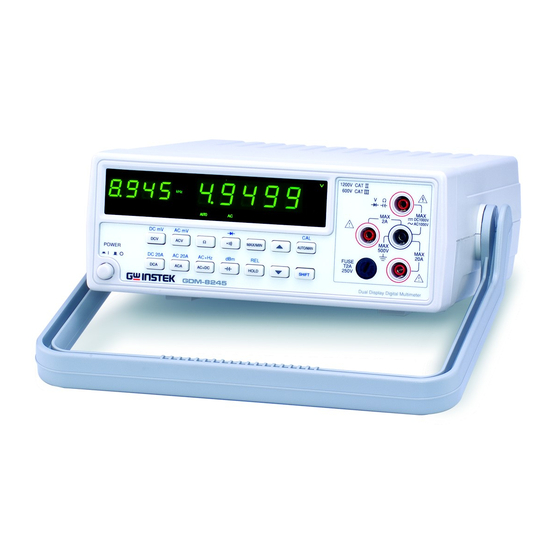
DUAL DISPLAY DIGITAL
MULTIMETER
MODEL: GDM-8245
User Manual
Good Will Instrument Co., Ltd.
GW Part No. 82DM-82450MD
Printed in Taiwan December 2003
Declaration of Conformity
We
GOOD WILL INSTRUMENT CO., LTD.
No. 95-11, Pao-Chung Rd., Hsin-Tien City, Taipei Hsien, Taiwan
GOOD WILL INSTRUMENT (SUZHOU) CO., LTD.
No.69 Lushan Road, Suzhou New District Jiangsu, China.
declares that the below mentioned product
GDM-8245
is herewith confirmed to comply with the requirements set out in the Council Directive
on the Approximation of the Law of Member States relating to Electromagnetic
Compatibility (89/336/EEC, 92/31/EEC, 93/68/EEC) and Low Voltage Equipment
Directive (73/23/EEC, 93/68/EEC).
For the evaluation regarding the Electromagnetic Compatibility and Low Voltage
Equipment Directive, the following standards were applied:
¡ ·
EMC
EN 61326-1:
Electrical equipment for measurement, control and laboratory use ––
EMC requirements (1997+A1: 1998)
Conducted and Radiated Emissions
CISPR 22 class B: 1993
Current Harmonic
EN 61000-3-2: 1995+A12: 1996
Voltage Fluctuation
EN 61000-3-3: 1995
-------------------------
-------------------------
-------------------------
¡ ·
Safety
Low Voltage Equipment Directive 73/23/EEC & amended by 93/68/EEC
EN 61010-1 : 2001
IEC 61010-1: 2001
Electrostatic Discharge
EN 61000-4-2: 1995
Radiated Immunity
EN 61000-4-3: 1996
Electrical Fast Transients
EN 61000-4-4: 1995
Surge Immunity
EN 61000-4-5: 1995
Conducted Susceptibility
EN 61000-4-6: 1996
Voltage Dips/ Interrupts
EN 61000-4-11: 1994
Advertisement

Related Manuals for GW Instek GDM-8245


Summary of Contents for GW Instek GDM-8245
- Page 1 MULTIMETER No.69 Lushan Road, Suzhou New District Jiangsu, China. declares that the below mentioned product MODEL: GDM-8245 GDM-8245 is herewith confirmed to comply with the requirements set out in the Council Directive on the Approximation of the Law of Member States relating to Electromagnetic Compatibility (89/336/EEC, 92/31/EEC, 93/68/EEC) and Low Voltage Equipment Directive (73/23/EEC, 93/68/EEC).
-
Page 2: Table Of Contents
DUAL DISPLAY DIGITAL MULTIMETER DUAL DISPLAY DIGITAL MULTIMETER USER MANUAL USER MANUAL 1.SAFETY SUMMARY TABLE OF CONTENTS PAGE SAFETY SUMMARY……………………………………………… Please take a moment to review these safety terms and symbols which may appear in this manual or on Equipment to prevent INTRODUCTION………………………………………………….. - Page 3 DUAL DISPLAY DIGITAL MULTIMETER DUAL DISPLAY DIGITAL MULTIMETER USER MANUAL USER MANUAL FOR UNITED KINGDOM ONLY DANGER High Voltage NOTE: This lead/appliance must only be wired by competent persons WARNING: THIS APPLIANCE MUST BE EARTHED ATTENTION refer to Manual IMPORTANT: The wires in this lead are coloured in accordance with the following code: Protective Conductor Terminal Green/ Yellow: Earth...
-
Page 4: Introduction
DUAL DISPLAY DIGITAL MULTIMETER DUAL DISPLAY DIGITAL MULTIMETER USER MANUAL USER MANUAL The wire which is coloured Blue must be connected to the 2. INTRODUCTION This instrument is a portable, bench-type dual display digital terminal which is marked with the letter N or coloured Blue multimeter with a good-performance 50000 counts designed for general or Black. -
Page 5: Specification
DUAL DISPLAY DIGITAL MULTIMETER DUAL DISPLAY DIGITAL MULTIMETER USER MANUAL USER MANUAL 3.SPECIFICATIONS RANGE RESOLUTION INPUT IMPEDANCE The specifications are operated under the essential conditions as follows: 10£ g V 10M£ [ 500mV A 1-year calibration cycle. 100£ g V 11.1 M£... - Page 6 DUAL DISPLAY DIGITAL MULTIMETER DUAL DISPLAY DIGITAL MULTIMETER USER MANUAL USER MANUAL 500£ g A,5mA,50mA,500mA,2A 5 ranges fuse protection. Protection 20A range no fuse,15 seconds max. 7.RESISTANCE When the input exceeds the full scale of the selected range, the display will appear RANGE RESOLUTION ACCURACY...
-
Page 7: Operation Instruction
An input is over-range if it exceeds the full scale of the selected range. Approx. 2.6 kg Weigh GDM-8245 indicates an input is over-range by lighting the “¡ X OL¡ X ” pattern on display. 4-5 No specification indication WARNING¡ G To avoid electrical shock, the power cord... - Page 8 DUAL DISPLAY DIGITAL MULTIMETER DUAL DISPLAY DIGITAL MULTIMETER USER MANUAL USER MANUAL 4-6 Input overload protection Figure 4-1 Front Panel The maximum allowable input is shown as table 4-1. Please proceed the measurement accordingly. Table 4-1: FUNCTION RANGE MAXIMUN INPUT 1200Vdc or peak ac 5V~1200V ACV (AC+DC)
-
Page 9: Measurement Tutorial
DUAL DISPLAY DIGITAL MULTIMETER DUAL DISPLAY DIGITAL MULTIMETER USER MANUAL USER MANUAL 5. MEASUREMENT TUTORIAL 5-3. Resistance, capacitance, continuity beeper measurements 1).Press the button to select function. 2).Press [¡ ¶ ]or[¡ ¿ ]to the desired range. Press [AUTO/MAN] button to 5-1. - Page 10 DUAL DISPLAY DIGITAL MULTIMETER DUAL DISPLAY DIGITAL MULTIMETER USER MANUAL USER MANUAL 5-8 MAX/MIN measurements For example, if [dBm] is pressed when measuring voltage in the max The MAX/MIN mode causes the DMM to hold the lowest and highest mode, the maximum value is converted to dBm. To release the dBm readings.
-
Page 11: Measurement Techniques
DUAL DISPLAY DIGITAL MULTIMETER DUAL DISPLAY DIGITAL MULTIMETER USER MANUAL USER MANUAL 6.MEASUREMENT TECHNIQUES Figure 6-1: Voltage Conversion 6-1 dBm measurement technique dBm is defined as above or below a 1mW reference. A voltage measurement is converted to dBm using the following formula: dBm=10*log (1000*voltage value /reference impedance.) - Page 13 DUAL DISPLAY DIGITAL MULTIMETER DUAL DISPLAY DIGITAL MULTIMETER USER MANUAL USER MANUAL Figure 6-2: Crest Factor 6-3 AC+DC measurement A signal includes an ac component and a dc level. The relationship between the total rms value of the signal and the ac component and the dc component is: rms total= component...
-
Page 15: Maintenance
DUAL DISPLAY DIGITAL MULTIMETER DUAL DISPLAY DIGITAL MULTIMETER USER MANUAL USER MANUAL 7.MAINTENANCE 7-3 Line voltage conversion The primary winding of the power transformer is tapped to permit The following instructions are executed by qualified personnel only. To operation from 100/120V, or 230V AC 50/60Hz line voltage. avoid electrical shock, do not perform any servicing other than the Conversion from one line voltage to another is done by changing the operating instructions unless you are qualified to do so.
Need help?
Do you have a question about the GDM-8245 and is the answer not in the manual?
Questions and answers