Sign In
Upload
Download
Table of Contents
Contents
Add to my manuals
Delete from my manuals
Share
URL of this page:
HTML Link:
Bookmark this page
Add
Manual will be automatically added to "My Manuals"
Print this page
×
Bookmark added
×
Added to my manuals
Manuals
Brands
Thermador Manuals
Oven
CM302B
Service manual
Thermador CM302B Service Manual
Built-in
Hide thumbs
1
Table Of Contents
2
3
4
5
6
7
8
9
10
11
12
13
14
15
16
17
18
19
20
21
22
23
24
25
26
27
28
29
30
31
32
33
34
35
36
37
38
39
40
41
42
43
44
45
46
47
48
49
50
51
52
53
54
55
56
57
58
59
60
61
62
63
64
65
66
67
68
69
70
71
72
73
74
75
76
77
78
79
80
81
82
83
84
85
86
87
88
89
90
91
92
93
94
95
96
97
98
99
100
101
102
103
104
105
106
107
108
109
110
111
112
page
of
112
Go
/
112
Contents
Table of Contents
Troubleshooting
Bookmarks
Table of Contents
Table of Contents
General
Data Plate Location
Symbols You will See in the Manual
Avoid Exposure to Excessive Microwave Energy
Cautions to Observe When Troubleshooting
Avoid Electrical Shock
Measuring for Microwave Radiation Leakage
Thermador Warranty
Servicing Components
Component Locations
Removing Trim, & Top Plenum Covers
Removing Electronic Oven Control Board
Removing Fuseblock & Microwave PCB Control
Removing Light Transformer
Double Line Break Relay
Removing Stirrer Motor
Transformer Air Switch Assembly
Removing Magnetron Fan Assembly
Removing Crossflow Top Cooling Blower
Removing High Voltage Microwave Capacitor
Removing High Voltage Diode
Removing High Voltage Microwave Transformer
Removing Magnetron, & Magnetron Thermal Cutout
Removing Control Panel Assembly
Display Board, & Touch Panel Glass
Removing Upper (or Single) Oven Door Switch
Monitor & Secondary Switch Assembly
Removing a Halogen Light Assembly
Removing Broil Element & Stirrer Blade Assembly
Removing Waveguide
Removing Convection Element & Motor
Removing Meat Probe Jack
Removing the Hidden Bake Element
Removing Oven Thermal Sensor
Removing Upper (or Single) Oven Door Gasket
Removing, Reinstalling Microwave Oven Door
Removing the Oven Door
Removing Upper (or Single) Oven Door Handle & Outer Glass Assembly
Removing an Oven Door Hinge, Actuator Arm, Center Glass, RF Screen, & Inner Glass
Troubleshooting
Testing Components, 20A Time-Delay Fuse
Transformer Cooling Fan Motor
Light Transformer, Double Line Break Relay
Stirrer Motor, High Voltage Diode
High Voltage Capacitor, High Voltage Transformer
Magnetron, Magnetron Thermal Cutout (TCO)
Magnetron Fan Motor, Crossflow Blower Motor
Door Latch Assembly
Door Latch Assembly, Monitor & Secondary Switches 55 Door Switch, Oven Thermal Sensor
Broil Element, Bake Element
Convection Element, Convection Motor
M/W Transformer Air Switch, Meat Probe Jack
Microwave PCB Control
Microwave Components Description
Interlock Switches
Latch Mounted Switch
Oven Mounted Switches
Switches Activated by Hook
20-Ampere Fuse, Fuse Failure
Diode, High Voltage Transformer, Magnetron Tube
Microwave Board, Stirrer Motor, Microwave Transformer Cooling Fan & Air Switch
"CM" Lower Oven
"CM" Relay Board Matrix
"CM" Dac Relay Board
Wire Harness
Wire Harnesses
Troubleshooting Chart for
Relay Board Headers Pin Failures
"CM" Oven Control Panel
Electronic Oven Controls
Control Panel Assembly
Glass Touch Panel
Display Head
Troubleshooting Chart for Display Head Pin Failures
CM Lower Oven Illustration
Removing Hidden Bake Element
Removing the Oven Temperature Sensor
Removing the Convection Bake Element
Removing a Convection Fan Motor
Removing a Halogen Lamp Holder
Removing Lamp Transformer
Lower Oven Double Line Break Relay
Removing Oven Light Switch, Oven Door Latch Assembly and High Temp Cut-Out
Removing the Air Switches
Side View
Removing a Blower
Removing Lower Oven Door
Removing Oven Door Gasket
Removing Oven Door Components
Removing Oven Module
Troubleshooting
Blower Motor, Air Switch
Convection Fan Motor, Lamp Transformer
The Convection Fan Motor
Oven Door Latrch Assembly
Hidden Bake Element, Broil Element
Convection Bake Element, Hi-Temp Cutout
The Convection
Fault Codes
Schematic & Wiring Diagrams
CM301 Schematic Diagram
CM301 Electronic Oven Control Wiring
CM302 Electronic Oven Control Wiring
CM301 Wiring Diagram
Advertisement
Quick Links
1
Fault Codes
Download this manual
SERVICE MANUAL
for
®
THERMADOR
BUILT-IN OVENS
Model CM302S
MODELS:
CM301B / CM301W / CM301S
CM302B / CM302W / CM302S
Lit. No. 94-30-006B
August, 2000
Table of
Contents
Previous
Page
Next
Page
1
2
3
4
5
Advertisement
Table of Contents
Troubleshooting
Cautions To Observe When Troubleshooting
6
Troubleshooting
51
Troubleshooting Chart for
78
Troubleshooting Chart for Display Head Pin Failures
85
Troubleshooting
105
Need help?
Do you have a question about the CM302B and is the answer not in the manual?
Ask a question
Questions and answers
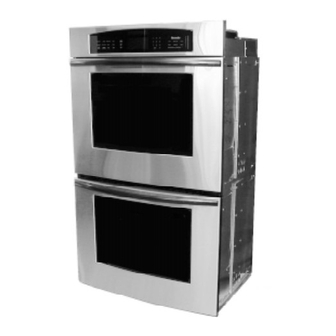
Related Manuals for Thermador CM302B
Oven Thermador CM302 Care And Use Manual
Thermador built-in ovens cm301, cm302 care & use manual (64 pages)
Oven Thermador CM301 Care And Use Manual
Built-in combination ovens (64 pages)
Oven Thermador C272 Installation Instructions Manual
(8 pages)
Oven THERMADOR SEC271 Installation Instructions Manual
Built-in electric convection ovens (32 pages)
Oven THERMADOR CM301 Care And Use Manual
Built-in combination ovens (64 pages)
Oven Thermador C272 Installation Instructions Manual
Built-in electric oven (8 pages)
Oven Thermador CMT-18 Service Manual
(54 pages)
Oven Thermador CM301B Service Manual
Built-in (112 pages)
Oven Thermador C271 Care And Use Manual
Thermador built-in double oven care & use manual (40 pages)
Oven Thermador C302 Service Manual
Built-in ovens (84 pages)
Oven Thermador CJ302 Care And Use Manual
Thermador built-in oven care & use manual (68 pages)
Oven Thermador CJ302 Care & Use Manual
(64 pages)
Oven Thermador CJ302B Service Manual
(121 pages)
Oven Thermador SMW272 Care & Use Manual
Thermador care & use manual for thermador built-in oven model: smw272 (64 pages)
Oven Thermador SC301 Care And Use Manual
Built-in oven (40 pages)
Oven Thermador Masterpiece Series Use And Care Manual
Built-in single, double and combination ovens (92 pages)
Summarization of Contents
GENERAL INFORMATION AND SAFETY
DATA PLATE LOCATION
Location of the oven's data plate, usually behind the cooling vent.
SAFETY AND OPERATIONAL PRECAUTIONS
SYMBOLS USED IN THE MANUAL
Explains warning, caution, tech tip, and service alert symbols.
AVOID MICROWAVE ENERGY EXPOSURE
Precautions to prevent exposure to microwave radiation during servicing.
TROUBLESHOOTING CAUTIONS
General safety precautions for troubleshooting microwave ovens.
AVOID ELECTRICAL SHOCK
Warnings and precautions related to avoiding electrical shock.
MICROWAVE RADIATION LEAKAGE MEASUREMENT
Steps for safely measuring microwave radiation leakage from the oven.
THERMADOR WARRANTY DETAILS
SERVICING OVEN COMPONENTS
COMPONENT LOCATIONS OVERVIEW
Identifies the location of various oven components.
REMOVING TRIM AND TOP PLENUM COVERS
Instructions for removing the oven's trim and top plenum covers.
REMOVING ELECTRONIC OVEN CONTROL BOARD
Step-by-step guide to remove the electronic oven control board.
REMOVING FUSEBLOCK AND MICROWAVE PCB
Instructions for removing the fuseblock and microwave PCB.
REMOVING LIGHT TRANSFORMER AND DOUBLE LINE BREAK RELAY
Steps to remove the light transformer and double line break relay.
REMOVING STIRRER MOTOR
Procedure for removing the stirrer motor from the oven.
REMOVING TRANSFORMER COOLING FAN AND AIR SWITCH
Guide to removing the transformer cooling fan and air switch.
REMOVING MAGNETRON FAN ASSEMBLY
Steps to remove the magnetron fan assembly.
REMOVING CROSSFLOW TOP COOLING BLOWER
Instructions for removing the crossflow top cooling blower.
REMOVING HIGH VOLTAGE MICROWAVE CAPACITOR
Procedure for removing the high voltage microwave capacitor.
REMOVING HIGH VOLTAGE DIODE
Steps to remove the high voltage diode.
REMOVING HIGH VOLTAGE MICROWAVE TRANSFORMER
Guide to removing the high voltage microwave transformer.
REMOVING MAGNETRON AND THERMAL CUTOUT
Instructions for removing the magnetron and its thermal cutout.
REMOVING CONTROL PANEL, DISPLAY BOARD, AND TOUCH PANEL GLASS
Steps to remove the control panel, display board, and touch panel glass.
REMOVING UPPER OVEN DOOR SWITCH
Procedure for removing the upper oven door switch.
REMOVING DOOR LATCH, HI-TEMP CUTOUT, MONITOR & SECONDARY SWITCHES
Steps to remove door latch, high-temp cutout, monitor, and secondary switches.
REMOVING HALOGEN LIGHT ASSEMBLY
Guide for removing the halogen lamp holder assembly.
REMOVING BROIL ELEMENT AND STIRRER BLADE ASSEMBLY
Instructions for removing the broil element and stirrer blade assembly.
REMOVING WAVEGUIDE
Steps for removing the waveguide.
REMOVING CONVECTION ELEMENT AND MOTOR
Guide to removing the convection element and motor.
REMOVING HIDDEN BAKE ELEMENT
Instructions for removing the hidden bake element.
REMOVING OVEN THERMAL SENSOR
Procedure for removing the oven thermal sensor.
REMOVING UPPER OVEN DOOR GASKET
Steps for removing the upper oven door gasket.
REMOVING AND REINSTALLING MICROWAVE OVEN DOOR
Procedure for removing and reinstalling the microwave oven door.
REMOVING UPPER OVEN DOOR HANDLE AND OUTER GLASS
Instructions for removing the oven door handle and outer glass.
REMOVING DOOR HINGE, ACTUATOR ARM, CENTER GLASS, RF SCREEN, AND INNER GLASS
Steps to remove door hinge, actuator arm, center glass, RF screen, and inner glass.
REMOVING OVEN MODULE (30" Convection Kit)
Steps to remove the 30" convection oven module.
TROUBLESHOOTING AND COMPONENT TESTING
GENERAL COMPONENT TESTING
General guidance on testing oven components.
TESTING BLOWER MOTOR AND AIR SWITCH
Testing procedures for blower motor and air switch.
TESTING CONVECTION FAN MOTOR AND LAMP TRANSFORMER
Testing procedures for convection fan motor and lamp transformer.
TESTING OVEN DOOR LATCH ASSEMBLY
Testing procedures for the oven door latch assembly.
TESTING HIDDEN BAKE AND BROIL ELEMENTS
Testing procedures for hidden bake and broil elements.
TESTING CONVECTION BAKE ELEMENT AND HI-TEMP CUTOUT
Testing procedures for convection bake element and hi-temp cutout.
FAULT CODE REFERENCE
WIRING DIAGRAMS
CM301 ELECTRONIC OVEN CONTROL WIRING
Wiring diagram for the CM301 electronic oven control.
CM302 ELECTRONIC OVEN CONTROL WIRING
Wiring diagram for the CM302 electronic oven control.
Table of Contents
Print
Rename the bookmark
Delete bookmark?
Delete from my manuals?
Login
Sign In
OR
Sign in with Facebook
Sign in with Google
Upload manual
Upload from disk
Upload from URL
Need help?
Do you have a question about the CM302B and is the answer not in the manual?
Questions and answers