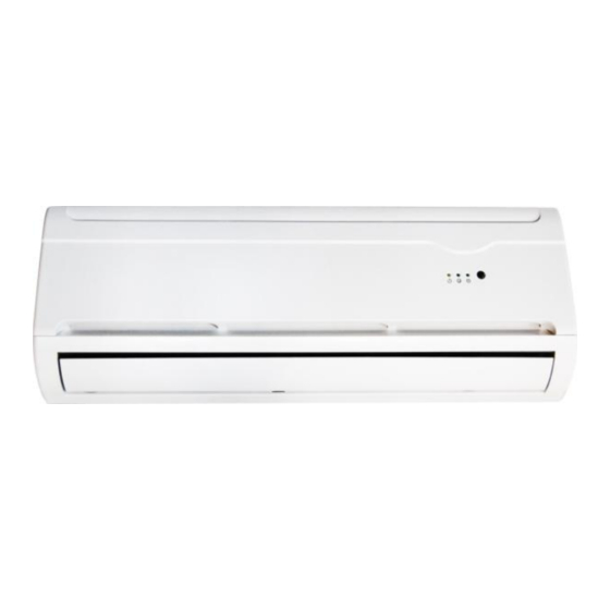
Summarization of Contents
1. Product Summary
Indoor Unit Models
Displays various indoor unit models with their capacities.
Outdoor Unit Models
Displays various outdoor unit models with their capacities.
2. Model Number Explanation
Model Code Breakdown
Detailed explanation of how to interpret the air conditioner's model number.
3. Installation and Safety
Safety Precautions
Instructions to prevent injury and damage during installation and operation.
Installation Warnings
Critical warnings regarding electrical safety and proper installation procedures.
Operation and Cautionary Notes
Operational Precautions
Guidelines for safe and effective operation of the air conditioner.
Installation Details
Installation Torque Specifications
Specific technical details and torque specifications for installation.
5. Refrigerant Cycle Diagrams
Cooling Cycle Diagram
Illustrates the refrigerant flow during the cooling operation mode.
Heat Pump Cycle Diagram
Illustrates the refrigerant flow for heat pump cooling and heating modes.
7. Wiring Diagrams
Indoor Unit Wiring Diagrams
Detailed circuit diagrams for the indoor unit's electrical components and connections.
Outdoor Unit Wiring Diagrams
Detailed circuit diagrams for the outdoor unit's electrical components and connections.
8. PCB Schematics
38 and 65 Series PCB Schematics
Schematic diagrams for 38 section and 65 Mitsubishi main chip PCBs.
85 Series PCB Schematics
Schematic diagrams for 85 section and 18NV 85 compatible PCBs.
Jin Dynasty 85 PCB Schematic
Schematic diagram for the Jin dynasty 85 model electrically controlled motherboard.
9. PCB Functions
Display Panel Functionality
Explains the various LED indicators and their meanings on the display panel.
Operation Mode Logic
Details the conditions and sequences for Cooling, Heating, and other operation modes.
Defrosting Procedures
Intelligent Defrost Process
Describes the automatic defrosting process based on sensor readings.
Outdoor PCB Defrost Control
Explains defrosting control logic managed by the outdoor PCB.
Outdoor Sensor Defrost Logic
Conditions for initiating and ending defrost based on outdoor sensor data.
Special Operating Modes
Dehumidification Mode
How the unit removes moisture from the air.
Ventilation and Automatic Modes
Describes the unit's performance in ventilation and automatic modes.
Control Features and Failure Codes
Time, Sleep, and Emergency Controls
Explains timer, sleep mode, and emergency key functions.
Failure Display Code Explanations
Explains LED indications for various fault conditions and their troubleshooting.
Detailed Failure Code Explanations
Comprehensive list of failure codes (E2-E4) and their troubleshooting steps.
More Failure Code Explanations
Continuation of failure codes (E5-E7) and troubleshooting steps.
Final Failure Code Explanations
Covers remaining failure codes (E8) and troubleshooting steps.
10. Troubleshooting Guides
Sensor Error Troubleshooting
Steps to diagnose and fix indoor Tr and TP1 sensor errors.
Indoor Fan Motor Issues
Troubleshooting guide for when the indoor fan motor does not operate.
Compressor Operation Problems
Diagnostic steps for issues related to the compressor not operating.
Remote Control and Transmission Issues
Troubleshooting steps for problems with the remote control and signal transmission.
General Unit Operation Checks
Flowchart for checking power, unit display, and basic operation.
Unit Not Operating Troubleshooting
Guide for when both indoor and outdoor units fail to operate.


Need help?
Do you have a question about the 9000BTU and is the answer not in the manual?
Questions and answers