Table of Contents
Advertisement
Thank you for choosing these Air Conditioners, please read this owner's manual carefully
before operation and retain it for future reference.
DC Inverter U-match Series
Floor Ceiling Type Unit
Installation Manual
Air Conditioners
Models:
Indoor Unit
ASKEL4H4R18
ASKEL4H4R24
ASKEL4H4R36
ASKEL4H4R48
Outdoor Unit
ASKCI4H4R18
ASKCI4H4R24
ASKCI4H4R36
ASKCI4H4R48
Advertisement
Table of Contents

Related Manuals for Air-Con ASKCI4H4R18


Summary of Contents for Air-Con ASKCI4H4R18
- Page 1 DC Inverter U-match Series Floor Ceiling Type Unit Installation Manual Air Conditioners Models: Indoor Unit Outdoor Unit ASKEL4H4R18 ASKCI4H4R18 ASKEL4H4R24 ASKCI4H4R24 ASKEL4H4R36 ASKCI4H4R36 ASKEL4H4R48 ASKCI4H4R48 Thank you for choosing these Air Conditioners, please read this owner’s manual carefully before operation and retain it for future reference.
-
Page 3: Table Of Contents
Contents 1 Safety Precautions ..................1 2 Outline of the Unit and Main Parts..............2 3 Preparative for Installation ................3 3.1 Standard Accessory Parts ................3 3.2 Selection of the Installation Location ............4 3.3 Connection Pipe Requirement ..............6 3.4 Electrical Requirement ................ -
Page 4: Safety Precautions
DC Inverter U-match Series Floor Ceiling Type Unit 1 Safety Precautions This mark indicates procedures which, if improperly performed, might lead to the WARNING! death or serious injury of the user. This mark indicates procedures which, if improperly performed, might possibly result CAUTION! in personal harm to the user, or damage to property. -
Page 5: Outline Of The Unit And Main Parts
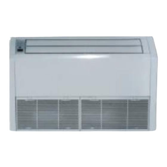
DC Inverter U-match Series Floor Ceiling Type Unit 2 Outline of the Unit and Main Parts Indoor 1. Guide louver 2. Air filter 3. Wired controller Outdoor 4. Wireless Controller Air inlet 5. Binding tape 6. Drain Pipe 7. Gas Pipe 8. -
Page 6: Preparative For Installation
DC Inverter U-match Series Floor Ceiling Type Unit 3 Preparative for Installation 3.1 Standard Accessory Parts The standard accessory parts listed below are furnished and should be used as required. Table 3.1 Indoor Unit Accessories Name Appearance Q'ty Usage To fix the hook on the cabinet Nut with Washer of the unit. -
Page 7: Selection Of The Installation Location
DC Inverter U-match Series Floor Ceiling Type Unit 3.2 Selection of the Installation Location WARNING! The unit must be installed where strong enough to withstand the weight of the unit and fixed securely, otherwise the unit would topple or fall off. CAUTION! ①... - Page 8 DC Inverter U-match Series Floor Ceiling Type Unit 3.2.2 Outdoor Unit WARNING! ① . Install the unit where it will not be tilted by more than 5°. ② . During installation, if the outdoor unit has to be exposed to strong wind, it must be fixed securely. If possible, do not install the unit where it will be exposed to direct sunlight.
-
Page 9: Connection Pipe Requirement
Item Length Indoor Unit and Diameter × wall Liquid Model Outdoor Unit (m) thickness) (mm) φ17×1.75 ASKEL4H4R18 ASKCI4H4R18 φ17×1.75 ASKEL4H4R24 ASKCI4H4R24 φ17×1.75 ASKEL4H4R36 ASKCI4H4R36 φ17×1.75 ASKEL4H4R48 ASKCI4H4R48 (1). The connecting pipe should be thermally insulated properly. (2). The pipe wall thickness shall be 0.5-1.0mm and the pipe wall shall be able to withstand the pressure of 6.0 MPa. - Page 10 DC Inverter U-match Series Floor Ceiling Type Unit accessible. The specifications of the breaker and power cable listed in the table above are determined ③ . based on the maximum power (maximum amps) of the unit. ④ . The specifications of the power cable listed in the table above are applied to the conduit- guarded multi-wire copper cable (like, YJV copper cable, consisting of PE insulated wires and a PVC cable jacket) used at 40°С...
-
Page 11: Installation Of The Unit
DC Inverter U-match Series Floor Ceiling Type Unit 4 Installation of the Unit 4.1 Installation of the Indoor Unit 4.1.1 Indoor unit dimension WARNING ! Install the indoor unit in a location which can withstand a load of at least five times the weight ①... - Page 12 DC Inverter U-match Series Floor Ceiling Type Unit 4.1.3 Indoor Unit Installation (1). Determine the location of the hanger through the paper template, and then remove the paper template. Anchor bolt Fig.4.2 (2). Insert the anchor bolts into the drilled holes, and drive the pins completely into the anchor bolts with a hammer.
-
Page 13: Installation Of The Outdoor Unit
DC Inverter U-match Series Floor Ceiling Type Unit ◆ Ceiling type Ceiling Suspension bolt Spring washer Right side Left side panel panel Hanger Fig.4.4 (6). Adjust the height of the unit to make the drain pipe slant slightly downward so that the drainage will become much smoother. - Page 14 DC Inverter U-match Series Floor Ceiling Type Unit 4.2.1 Outdoor unit dimension Fig.4.6 Table 4.2 Unit: mm Item Model ASKCI4H4R18 ASKCI4H4R24 ASKCI4H4R36 1107 1100 ASKCI4H4R48 1349 4.2.2 Condensate Drainage of the Outdoor Unit(Only for the heat pump unit) (Fig.10) (1). It is required to install a drain pipe for the outdoor unit to drain out the condensate water during heating operation.
-
Page 15: Installation Of The Connection Pipe
DC Inverter U-match Series Floor Ceiling Type Unit 4.3 Installation of the Connection Pipe 4.3.1 Flare Processing (1). Cut the connection pipe with the pipe cutter and remove the burrs. (2). Hold the pipe downward to prevent cuttings from entering the pipe. (3). - Page 16 DC Inverter U-match Series Floor Ceiling Type Unit 4.3.3 Connecting the Pipe at the Indoor Unit Side Detach the caps and plugs from the pipes. CAUTION! ① . Be sure to apply the pipe against the port on the indoor unit correctly. If the centering is improper, the flare nut cannot be tightened smoothly.
- Page 17 DC Inverter U-match Series Floor Ceiling Type Unit Table 4.3 Flare nut tightening torque Pipe Diameter Tightening Torque 1/4˝(Inch) 15-30 (N·m) 3/8˝(Inch) 35-40 (N·m) 5/8˝(Inch) 60-65 (N·m) 1/2˝(Inch) 45-50 (N·m) 3/4˝(Inch) 70-75 (N·m) 7/8˝(Inch) 80-85 (N·m) CAUTION! Be sure to connect the gas pipe after connecting the liquid pipe completely. 4.3.4 Connecting the Pipe at the Outdoor Side Unit Tighten the flare nut of the connection pipe at the outdoor unit valve connector.
-
Page 18: Vacuum And Gas Leakage Inspection
DC Inverter U-match Series Floor Ceiling Type Unit 4.3.7Liquid Pipe and Drain Pipe Sealed If the outdoor unit is installed lower than the indoor unit (See Fig.4.15) Saddle (1). A drain pipe should be above ground and the end of the pipe does not dip into water. - Page 19 DC Inverter U-match Series Floor Ceiling Type Unit assembly should be kept closed, otherwise evacuation would fail. (5). The evacuation duration depends on the unit’s capacity, generally, 20 minutes for the 18K units, 30 minutes for the 24/36K units, 45 minutes for the 48K units, And verify if the pressure gauge at the low pressure side of the manifold valve assembly reads -1.0Mp (-75cmHg), if not, it indicates there is leak somewhere.
-
Page 20: Installation Of The Drain Pipe
DC Inverter U-match Series Floor Ceiling Type Unit an oil bend should be employed for every 6 meters. Outdoor Oil bend Indoor Oil bend Fig.4.18 4.5 Installation of the Drain Pipe 4.5.1 Precautions When Doing the Piping Work (1). Keep piping as short as possible and slope it downwards at a gradient of at least 1/100 so that air may not remain trapped inside the pipe. - Page 21 DC Inverter U-match Series Floor Ceiling Type Unit 4.5.2 Installing the Drain Pipes (1). For determining the position of the drain hose, perform the following procedures. (2). Insert the drain pipe to the drain outlet of the unit and then tighten the clamp securely with tape.
-
Page 22: Electrical Wiring
DC Inverter U-match Series Floor Ceiling Type Unit Ceiling type Floor type Fig.4.25 4.6 Electrical Wiring 4.6.1 Wiring Precautions WARNING ! ① . Before obtaining access to terminals, all supply circuits must be disconnected. ② . The rated voltage of the unit is as shown as Table 3.4 and Table 3.5. ③... - Page 23 DC Inverter U-match Series Floor Ceiling Type Unit 4). Shape the loop wire properly, place it on the terminal board and tighten securely with the terminal screw using a screwdriver. (2). For strand wiring (Fig.4.26) 1). Cut the wire end with a wire cutter or wire-cutting pliers, then strip the insulation about 25 (15/16") 2).
- Page 24 DC Inverter U-match Series Floor Ceiling Type Unit (4). Electric wiring between the indoor and outdoor units Single-phase units(18/24/36/48K) ASKCI4H4R18 + ASKEL4H4R18 ① . Power cord 3×1.5mm (H07RN-F) ② . Power cord 3×1.0mm (H05RN-F) ③ . Communication Cords 2×0.75mm (H05RN-F)
- Page 25 DC Inverter U-match Series Floor Ceiling Type Unit CAUTION! ① . The power cord and the wire of the fresh air valve are high-voltage, while the communication cord and connection wire of the wired controller are low-voltage. They should run separately against electromagnetic interference.
-
Page 26: Installation Of Controllers
DC Inverter U-match Series Floor Ceiling Type Unit Power lines should go along the right side plate and be fixed to the fixation hook with binding wires to keep Routing of External no contact with pipelines. Communication lines between Power Lines indoor and outdoor units also should go along the right side plate and keep away from power lines. - Page 27 DC Inverter U-match Series Floor Ceiling Type Unit IPM protection DC fan motor error Drive desynchronizing protection Pfc protection Activation failure Compressor phase sequence protection Compressor stalling protection Power protection Indoor and outdoor mismatch 4-way valve direction changing protection Drive reset protection Over-current protection Communication error between main control and drive Drive module sensor error...
-
Page 28: Working Temperature Range
DC Inverter U-match Series Floor Ceiling Type Unit 6.2 Working Temperature Range Table 6.2 Indoor Side Outdoor Side Test Condition DB(°C) WB(°C) DB(°C) WB(°C) Nominal Cooling − Nominal Heating − Rated Cooling − Low Temp. Cooling − Rated Heating − Low Temp. -
Page 29: Routine Maintenance
Note: After carrying out the check of the above items and taking relevant measures to solve the problems found but the air-conditioning unit still does not function well, please stop the operation of the unit immediately and contact the local service agency designated by AIR-CON. Only ask professional serviceman to check and repair the unit. - Page 30 DC Inverter U-match Series Floor Ceiling Type Unit 2. Clean the filer screen Clean the filer screen by a vacuum cleaner or wash it by flashing water. If the oil stain on the filter can not be removed or cleaned up, wash it by warm water meld with the detergent.
Need help?
Do you have a question about the ASKCI4H4R18 and is the answer not in the manual?
Questions and answers