
Related Manuals for Air-Con ACZEM4C4R18


Summary of Contents for Air-Con ACZEM4C4R18
-
Page 1: Service Manual
Service Manual Model: ACZEM4C4R18/ACZCI4C4R18 ACZEM4H4R18/ACZCI4H4R18 ACZEM4C4R24/ACZCI4C4R24 ACZEM4H4R24/ACZCI4H4R24 (Refrigerant:R410A) GREE ELECTRIC APPLIANCES,INC.OF ZHUHAI... -
Page 2: Table Of Contents
Service Manual Table of Contents Part Ⅰ : Technical Information ................. 1 1. Summary ........................1 2. Specifications ......................2 2.1 Specification Sheet ......................2 2.2 Operation Characteristic Curve ..................6 2.3 Capacity Variation Ratio According to Temperature ............6 2.4 Cooling and Heating Data Sheet in Rated Frequency ............ - Page 3 Service Manual 9. Maintenance ......................... 36 9.1 Malfunction Analysis ......................36 9.2 Flashing LED of Indoor/Outdoor Unit and Primary Judgement ........... 40 9.3 How to Check Simply the Main Part ..................45 10. Exploded Views and Parts List ..............61 10.1 Indoor Unit .........................
-
Page 4: Part Ⅰ : Technical Information
Service Manual Part Ⅰ : Technical Information 1. Summary Indoor Unit: ACZEM4C4R18 ACZEM4H4R18 ACZEM4C4R24 ACZEM4H4R24 Outdoor Unit: ACZCI4C4R18 ACZCI4H4R18 ACZCI4C4R24 ACZCI4H4R24 Remote Controller: YX1FF T-ON T-OFF AUTO SWING COOL SLEEP LOCK SPEED HEAT ON/OFF MODE SWING SLEEP TIMER Technical Information... -
Page 5: Specifications
Service Manual 2. Specifications 2.1 Specification Sheet Model ACZEM4C4R18/ACZCI4C4R18 ACZEM4H4R18/ACZCI4H4R18 Product Code CB162008600_L17107 CB162008000_L14385 V ~ Rated Voltage 208/230 208/230 Power Rated Frequency Supply Phases Power Supply Mode Outdoor Outdoor Btu/h Cooling Capacity(Min ~ Max) 18000(2201~20001) 18000(2201~20001) Btu/h Heating Capacity(Min ~ Max) 19000(3050~23500) Cooling Power Input(Min ~... - Page 6 Service Manual Outdoor Unit Model ACZCI4C4R18 ACZCI4H4R18 Outdoor Unit Product Code CB145W04100_L17107 CB145W04200_L14385 ZHUHAI LANDA COMPRESSOR ZHUHAI LANDA COMPRESSOR Compressor Manufacturer CO.,LTD CO.,LTD QXA-B141zF030A QXA-B141zF030A Compressor Model Compressor Oil 68EP 68EP Compressor Type Rotary Rotary Compressor LRA. Compressor RLA Compressor Power Input 1440 1440 Compressor Overload Protector...
- Page 7 Service Manual Model ACZEM4C4R24/ACZCI4C4R24 ACZEM4H4R24/ACZCI4H4R24 Product Code CB162008500_L17107 CB162007900_L14385 V ~ Rated Voltage 208/230 208/230 Power Rated Frequency Supply Phases Power Supply Mode Outdoor Outdoor Btu/h Cooling Capacity(Min ~ Max) 22000(8630~23200) 22000(8630-23200) Btu/h Heating Capacity(Min ~ Max) 23000(8650~26000) Cooling Power Input(Min ~ Max) 2310(600~2700) 2310(600~2700) Heating Power Input(Min ~...
- Page 8 Service Manual Outdoor Unit Model ACZCI4C4R24 ACZCI4H4R24 Outdoor Unit Product Code CB145W03900_L17107 CB145W04000_L14385 ZHUHAI LANDA COMPRESSOR ZHUHAI LANDA COMPRESSOR Compressor Manufacturer CO.,LTD CO.,LTD QXA-B141zF030A QXA-B141zF030A Compressor Model Compressor Oil 68EP 68EP Compressor Type Rotary Rotary Compressor LRA. Compressor RLA Compressor Power Input 1440 1440 Compressor Overload Protector...
-
Page 9: Operation Characteristic Curve
Service Manual 2.2 Operation Characteristic Curve Cooling Heating 220V •Conditions 220V Indoor DB 80F/WB 67 F Outdoor : DB 95F/WB75F Indoor air flow : Turbo Pipe length : 24.6 ft. 230V 230V 240V •Conditions Indoor : DB 70F/WB 60F 240V Outdoor : DB 47F/WB 43F Indoor air flow : Turbo Pipe length : 24.6 ft. -
Page 10: Cooling And Heating Data Sheet In Rated Frequency
(DB/WB) indoor outdoor unit (rps) unit unit Indoor Outdoor T1 (°F) T2 (°F) P (MPa) ACZEM4C4R18/ACZCI4C4R18 0.9 to 1.1 53.6 to 57.2 109.4 to 105.8 ACZEM4H4R18/ACZCI4H4R18 Turbo High 80/67 95/75 ACZEM4C4R24/ACZCI4C4R24 0.8 to 1.0 50 to 53.6 181.4 to 113... -
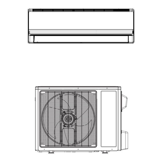
Page 11: Outline Dimension Diagram
Service Manual 3. Outline Dimension Diagram 3.1 Indoor Unit 27 1/3 7 2/3 ACZEM4C4R18 ACZEM4H4R18 Ф2 1/6 Ф2 1/6 1 2/9 3 6/7 5 3/7 7 2/7 ACZEM4C4R24 ACZEM4H4R24 Ф2 3/4 Ф2 3/4 Unit:inch 3 1/2 2 5/9 Model ACZEM4C4R18... -
Page 12: Outdoor Unit
Service Manual 3.2 Outdoor Unit 13 2/5 15 3/5 37 3/5 Unit:inch Technical Information... -
Page 13: Refrigerant System Diagram
Di s charge Heat Accumlator Suction exchanger Compressor (evaporator) Heat exchanger Liquid pipe (condenser) side Valve Strainer Capillary Strainer COOLING HEATING Refrigerant pipe diameter Liquid pipe : 1/4" Gas pipe : 1/2"(For ACZEM4C4R18/ACZCI4C4R18 ACZEM4H4R18/ACZCI4H4R18) Gas pipe : 5/8"(For ACZEM4C4R24/ACZCI4C4R24 ACZEM4H4R24/ACZCI4H4R24) Technical Information... -
Page 14: Electrical Part
Grounding wire YEGN Yellow/Green Black Violet Orange Note: Jumper cap is used to determine fan speed and the swing angle of horizontal lover for this model. ● Indoor Unit Models: ACZEM4C4R18 ACZEM4H4R18 TUBE TEMP. ROOM TEMP. SENSOR SENSOR FAN MOTOR... - Page 15 Service Manual Models: ACZEM4C4R24 ACZEM4H4R24 WARNING Please don't touch any electronic component ROOM TUBE TEMP. TEMP. or terminal when the machine is running, stopping or has been powered off for less SENSOR SENSOR than 3 minutes to prevent electric shock ! MAGNETIC CONNECTING RING...
-
Page 16: Printed Circuit Board
Service Manual ●Outdoor Unit Models: ACZCI4C4R18 ACZCI4C4R24 WARNING Please don't touch any electronic component or terminal when the COMP. machine is running , stopping or YEGN COMP has been powered off for less than 30 minutes to prevent the risk of electric shock ! MAGNETIC RING TERMINAL... -
Page 17: Pcb Printed Diagram
Service Manual 5.2 PCB Printed Diagram ● Indoor Unit Models: ACZEM4C4R18 ACZEM4H4R18 ● Top view Live wire interface Neutral wire interface Fuse PG Motor Auto button Up and down swing terminal interface PG feedback IDU and ODU communication interface Display terminal interface Jumper Ambient temp. - Page 18 Service Manual Models: ACZEM4C4R24 ACZEM4H4R24 ● Top view DC fan interface Auto button Up and down swing terminal interface Display terminal interface Jumper cap Ambient temp. sensor Tube temp. sensor IDU and ODU communication interface Live wire interface Fuse Neutral wire interface Earth wire terminal interface ●...
- Page 19 Service Manual Outdoor Unit ● Top view Compressor wiring connection terminal ODU heat exchanger middle copper pipe temp. sensor terminal Compressor overload protection terminal ODU temp. sensor terminal EXV terminal Outdoor fan terminal Four-way valve terminal Chassis electric heating wiring terminal Communication cable with IDU Power supply live wire...
-
Page 20: Function And Control
Service Manual 6. Function and Control 6.1 Remote Controller Introduction Buttons on Remote Controller ON/OFF button T-ON T-OFF AUTO MODE button SWING COOL SLEEP LOCK SPEED HEAT +/- botton MODE ON/OFF FAN button SWING SWING button SLEEP TIMER SLEEP button TIMER button Icon Display on Remote Controller Timer on Timer off... - Page 21 Service Manual When selecting auto mode, air conditioner will operate automatically according to Ambient Temperature. Set temperature can't be adjusted and won't be displayed either. Press FAN button to adjust fan speed. (This function is not available in this air conditioner.) When selecting cool mode, air conditioner will operate under cool mode.
- Page 22 Service Manual Replacement of Batteries in Remote Controller battery 1. Press the back side of remote controller on the spot marked with , and then push out the cover of battery box along the arrow direction. 2. Replace two No.7 (AAA 1.5V) dry batteries and make sure the positions of + and -- polar are correct.
-
Page 23: Brief Description Of Modes And Functions
Service Manual 6.2 Brief Description of Modes and Functions 1 General introduction (1) Buzzer When the controller is energized or receives any command or signal from the buttons or the remote controller, the buzzer will give out a beep. (2) Display Dual-8 nixie After energizing, the unit will display all icons. - Page 24 Service Manual Start cooling Tamb. Tpreset -32.9F Original operating status Tpreset –35.6 F Stop cooling 7 min. 3 min. 7 min. Graphic instruction: (Same as below) Compressor Indicates operation Outdoor fan motor Indicates stop Indoor fan motor Set fan speed ②...
- Page 25 Service Manual fan motor blows residual heat for a while at set speed to prevent high temperature inside the unit. ◆ When Tset+38.3 F < Tamb. < Tset+41 F, the unit will maintain its previous operation status. ◆ When the unit stops due to malfunction or protection, the compressor, IDU fan motor and ODU fan motor stop operation. ◆...
- Page 26 Service Manual ◆ Timer ON: If timer ON is set during operation of the unit, the unit will continue to operate. If timer ON is set at unit OFF, upon ON time reaches the unit will start to run according to previous setting status. ◆...
- Page 27 Service Manual ④ Swing function is available only when swing function is set and IDU fan motor is operating. (8) Display of nixie tube on indoor unit ◆ When energized & started for the first time, the nixie tube defaults to displaying current set temperature. ◆...
- Page 28 Service Manual closed by pressing the HEALTH button on remote controller or turning off the unit. ② If the unit is equipped with the remote controller without HEALTH button, the unit defaults health function ON. Health function will be closed when turning off the unit. (2) I FEELfunction When I FEEL command is received, the controller will operate according to the ambient temperature sent by the remote controller (For defrosting and cold air prevention, the unit operates according to the ambient temperature sensed by the air conditioner).
- Page 29 Service Manual (9) Compressor overload protection (indoor unit displays H3 in cooling, heating or dry mode) ① If disconnection of compressor overload switch is detected for 3S continuously, the system will stop for compressor overload protection; when the protection is eliminated and the compressor has stopped for 3min, the unit will resume running; ②...
-
Page 30: Part Ⅱ : Installation And Maintenance
Service Manual Part Ⅱ : Installation and Maintenance 7. Notes for Installation and Maintenance Safety Precautions: 10. If the power cord or connection wire is not long enough, please get the specialized power cord or connection wire Important! from the manufacture or distributor. Prohibit prolong the wire by yourself. - Page 31 Service Manual Main Tools for Installation and Maintenance 1. Level meter, measuring tape 2. Screw driver 3. Impact drill, drill head, electric drill 4. Electroprobe 5. Universal meter 6. Torque wrench, open-end wrench, inner hexagon spanner 7. Electronic leakage detector 8.
-
Page 32: Installation
Service Manual 8. Installation 8.1 Installation Dimension Diagram Space to the wall Space to the wall At least 5 8/9 inch At least 5 8/9 inch Drainage pipe Installation and Maintenance... -
Page 33: Installation Procedures
Service Manual Installation procedures Start installation Preparation before installation Read the requirements select installation Prepare tools for electric connection location Select indoor unit Select outdoor unit installation location installation location Install the support of outdoor unit Install wall-mounting (select it according to the actual situation) frame, drill wall holes Connect pipes of indoor Fix outdoor unit... -
Page 34: Installation Parts-Checking
Owner’s manual, Connecting conditioner. cable(power cord) remote controller Air switch capacity Air-conditioner Wall pipe ACZEM4C4R18/ACZCI4C4R18 Note: ACZEM4H4R18/ACZCI4H4R18 1.Please contact the local agent for installation. ACZEM4C4R24/ACZCI4C4R24 2.Don't use unqualified power cord. ACZEM4H4R24/ACZCI4H4R24 (4) Properly connect the live wire, neutral wire and grounding wire of power socket. - Page 35 Service Manual in the holes. 5. Connect the Pipe of Indoor Unit (3) Fix the wall-mounting frame on the wall with tapping screws (1) Aim the pipe joint at the corresponding bellmouth.(As show (ST4.2X25TA) and then check if the frame is firmly installed by in Fig.5) pulling the frame.
- Page 36 Service Manual 7. Connect Wire of Indoor Unit 8. Bind up Pipe (1) Open the panel, remove the screw on the wiring cover and (1) Bind up the connection pipe, power cord and drain hose then take down the cover.(As show in Fig.11) with the band.(As show in Fig.14) (2) Reserve a certain length of drain hose and power cord Panel...
-
Page 37: Installation Of Outdoor Unit
Service Manual Refer to the following table for wrench moment of force: 8.6 Installation of Outdoor Unit 1. Fix the Support of Outdoor Unit(select it according to the actual installation situation) Hex nut diameter(inch) Tightening torque(ft·Ibf) (1) Select installation location according to the house structure. Φ1/4 11.10~14.75 (2) Fix the support of outdoor unit on the selected location with... -
Page 38: Vacuum Pumping And Leak Detection
Service Manual Note: 2. Leakage Detection (1) The through-wall height of drain hose shouldn't be higher (1) With leakage detector: than the outlet pipe hole of indoor unit.(As show in Fig.25) Check if there is leakage with leakage detector. (2) Slant the drain hose slightly downwards. The drain hose (2) With soap water: can't be curved, raised and fluctuant, etc.(As show in Fig.26) If leakage detector is not available, please use soap water for... -
Page 39: Maintenance
Service Manual 9. Maintenance 9.1 Malfunction Analysis Note: When replacing the controller, be sure to insert the wire jumper into the new controller, otherwise the unit will display C5 Measure insulation resistance The breaker trips at once when it to ground to see if there is any is set to “ON”. - Page 40 Service Manual Improper set of temperature Adjust set temperature If cooling (heating) load is Check the forecasted load of cooling (heating) proper Check and fill the leakage, then The refrigerant has leakage or is vacuumize it and supplement the re- insufficient frigerant as required Leakage between the high pres-...
- Page 41 Service Manual The indoor fan motor is burned or breaks or has the heat protector Replace the fan motor or the defective part. malfunction. The built-in heat protector of the Replace the fan motor The fan does not motor breaks frequently because the run when it is set motor is abnormal.
- Page 42 Service Manual The torque of the swing motor is not enough First, check whether the connection is Wrong connection The swing fan wrong. If no, replace the parts does not run. The controller is damaged(IC2003 is damaged, the swing relay can not close, etc) C o n t r o l l e r m a l f u n c t i o n ( I C 2 0 0 3 Change controller...
-
Page 43: Flashing Led Of Indoor/Outdoor Unit And Primary Judgement
Service Manual 9.2 Flashing LED of Indoor/Outdoor Unit and Primary Judgement Indoor unit displaying method Outdoor unit display(LEDs have 3 Indicator display(LED blinks status)□OFF ■ON ☆ Blinks Double Name of 0.5s-ON/0.5s-OFF) AC status Malfunctions malfunction 8 code Running Cooling Heating D42/ D43/ display... - Page 44 Service Manual 1.Exhaust temp sensor Cooling,dehumidifying;after Outdoor hasn’t connected well,or runing for 3mins later,the air exhaust Off 3s damaged,plwease refer to compressor will stop to blinks 5 □ □ the sensor resistance value ☆ ☆ sensor open run,indoor fan motor will start circuit,short for checking.
- Page 45 Service Manual Cooling, dehumidifying;compressor Off 3s 23 PFC protection blink 6 □ ■ stops running,indoor fan Pls refer to troubleshooting ☆ ☆ motor works. times Heating: all will stop running Cooling, dehumidifying;compressor Off 3s Compressor blink 7 □ ■ stops running,indoor fan Pls refer to troubleshooting ☆...
- Page 46 Service Manual All loads work normally but Anti-freezing Indoor unit air return is poor ■ ■ ■ □ the running frequency limited lImit/decrease or fan speed is to low. frequency or decrease 1.The wire terminal of outdoor fan motor is Cooling:outdoor fan loosed,fix the terminal.
- Page 47 Service Manual Test value under normal condition Test point No. Test point Related elements Neutralwire, live wire Test 1 Between A and C 160V-265V Neutralwire, live wire Test 2 Between B and C 160V-265V Test 3 Between D and E Electrolytic capacitor of DC bas bar DC 180V-380V Between F and G...
-
Page 48: How To Check Simply The Main Part
Service Manual 9.3 How to Check Simply the Main Part Confirm the malfunction type according to the malfunction indicator of indoor/outdoor unit and malfunction sheet (usually the sheet will be stuck on the electric box cover or top cover of the unit). As long as there is a malfunction, the indicator of the outdoor controller board will display the corresponding malfunction directly;... - Page 49 Service Manual 1.Malfunction of Temperature Sensor F1,F2 Troubleshooting for F1,F2 malfunction the wiring terminal between the temperature sensor and the controller loosened or poorly contacted? Insert the temperature sensor tightly Is malfunction eliminated Is there short circuit due to trip - over of the parts? Make the parts upright Is malfunction...
- Page 50 Service Manual 2. Malfunction of Blocked Protection of IDU Fan Motor H6 ACZEM4C4R18 ACZEM4H4R18 Troubleshooting for H6 malfunction Stir the blade with a tool to see whether the blade rotates smoothly Tighten the screw; reassemble the blade, motor and shaft bearing rubber base sub-assy to make...
-
Page 51: Installation And Maintenance
Service Manual ACZEM4C4R24 ACZEM4H4R24 Start Turn the fan blades by hand under power-off condition Adjust the motor and blade Whether the fan blades assembly so that rotor can run can run smoothly? smoothly. Turn unit on to check whether the malfunction is eliminated. - Page 52 Service Manual 3. Malfunction of Protection of Jumper Cap C5 Troubleshooting for C5 malfunction Appearance of Is there jumper cap on the the jumper cap mainboard ? Assemble the jumper cap with the same model Is malfunction eliminated the jumper cap inserted correctly and tightly ? Insert the...
- Page 53 Service Manual 4. Communication malfunction E6 Start Cut off power, check if the wire between indoor unit and outdoor unit, and the wire inside electric box are connected correctly Reconnect the wire Malfunction is according to Connected correctly? eliminated wiring diagram Is there incorrect Match them match between the mainboard...
- Page 54 Service Manual 5. Malfunction of Zero-crossing Inspection Circuit Malfunction of the IDU Fan Motor U8 Troubleshooting for U8 malfunction Re-energize1 minute after de-erergization The unit returns to normal. Conclusion:U8 is displayed due U8 is still to instant energization afte de- displayed energization while the capacitor discharges slowly.
- Page 55 Service Manual 6. Capacitor charging malfunction (outdoor unit malfunction) Outdoor unit malfunction indicator status □ ■ □ ■ Main detection point: ●Detect if the voltage of L and N terminal of wiring board is between 210AC-240AC by alternating voltage meter; ●Is reactor (L) well connected? Is connection wire loosened or pull-out? Is reactor (L) damaged? Malfunction diagnosis process: Turn on the unit...
- Page 56 Service Manual 7. IPM protection, desynchronizing malfunction, phase current of compressor is overcurrent (outdoor unit malfunction) Outdoor unit malfunction indicator status Malfunction □ ☆ □ ■ IPM protection Desynchronizing malfunction □ ☆ ■ ☆ Compressor overcurrent □ ☆ □ □ Main detection point: ●If control board AP1 and compressor COMP is well connected? If they are loosened? If the connection sequence is correct? ●Is voltage input in the normal range (Test the voltage between L, N of wiring board XT by DC voltage meter)?
- Page 57 Service Manual Energize and switch on Use AC voltmeter Check the supply to measure the If the voltage IPM protection voltage and voltage between between terminal L and N on wiring occurs after the machine has run for restore it to terminal L and N board XT is within a period of time?
- Page 58 Service Manual 8. Diagnosis for high temperature, overload protection (check outdoor unit in cooling mode and check indoor unit in heating mode) Outdoor unit malfunction indicator status ■ □ ■ ■ Main detection point: ●If the outdoor ambient temperature is in normal range; ●If the indoor and outdoor fan is running normally;...
- Page 59 Service Manual 9. Diagnosis for failure start up malfunction (outdoor unit malfunction) Outdoor unit malfunction indicator status □ ☆ □ ☆ Main detection point: ●If the compressor wiring is correct? ●If the stop time of compressor is enough? ●If the compressor is damaged? ●If the refrigerant charging is too much? Malfunction diagnosis process: Energize the unit...
- Page 60 Service Manual 10. Diagnosis for compressor synchronism (outdoor unit malfunction) Outdoor unit malfunction indicator status □ ☆ ■ ☆ Main detection point: ●If the system pressure is over-high? ●If the working voltage is over-low? Malfunction diagnosis process: Synchronism Synchronism after occurred during energize the unit operation...
- Page 61 Service Manual 11. Diagnosis for overload and discharge malfunction (outdoor unit malfunction) Outdoor unit malfunction indicator status Malfunction Overload □ ☆ ☆ □ Discharge ■ □ ■ ☆ Main detection point: ●If the electron expansion valve is connected well? Is the expansion valve damaged? ●If the refrigerant is leakage? ●If the overload protector is damaged? ●If the discharge temp sensor is damaged?
- Page 62 Service Manual 12. Communication malfunction Outdoor unit malfunction indicator status □ □ □ ☆ Main detection point: ●Check if the connection wire and the built-in wiring of indoor and outdoor unit is connected well and no damaged; ●If the communication circuit of indoor mainboard is damaged? If the communication circuit of outdoor mainboard (AP1) is damaged? Malfunction diagnosis process: Start If the unit is operating...
- Page 63 Service Manual Diagnosis process for outdoor communication circuit (refer to the key detection points of outdoor unit) Start Test voltage valueof Test10 position in diagram with voltage meter Number jumping Test voltage value of Test 13 position in diagram with voltage meter Number jumping Outdoor unit...
-
Page 64: Exploded Views And Parts List
Service Manual 10. Exploded Views and Parts List 10.1 Indoor Unit Models: ACZEM4C4R18 ACZEM4H4R18 T-ON T-OFF AUTO SWING COOL SLEEP LOCK SPEED HEAT ON/OFF MODE SWING SLEEP TIMER Installation and Maintenance... - Page 65 Service Manual Part Code Description ACZEM4C4R18 ACZEM4H4R18 Product Code CB162N08600_L17107 CB162N08000_L14385 Front Panel Assy 20012286_L17107 20012286_L14385 Filter Sub-Assy 1112208901 1112208901 Screw Cover 24252016 24252016 Front Case Sub-Assy 20022172 20022172 Guide Louver 10512115 10512115 Air Louver 1 10512708 10512708 Helicoid tongue...
- Page 66 Service Manual Models: GWC24MD-D3DNA5K/I GWH24MD-D3DNA5K/I T-ON T-OFF AUTO SWING COOL SLEEP LOCK SPEED HEAT ON/OFF MODE SWING SLEEP TIMER Installation and Maintenance...
- Page 67 Service Manual Part Code Description ACZEM4C4R24 ACZEM4H4R24 Product Code CB162N08500_L17107 CB162N07900_L14385 Front Panel Assy 20012368_L17107 20012368_L14385 Filter Sub-Assy 11122091 11122091 Screw Cover 24252016 24252016 Front Case-Assy 2001232901 2001232901 Air Louver 10512141 10512141 Helicoid tongue 26112187 26112187 Left Axile Bush 10512037 10512037 Rear CaseAssy 2220211701...
-
Page 68: Outdoor Unit
Service Manual 10.2 Outdoor Unit Model: ACZCI4C4R18 Installation and Maintenance... - Page 69 Service Manual Part Code Description ACZCI4C4R18 Product Code CB145W04100_L17107 Front Grill 01473049 Cabinet 01433047P Axial Flow Fan 10335008 Fan Motor 1501506402 Chassis Sub-assy 02803281P Clapboard Assy 01233153 Compressor and Fittings 00105249G Inhalation Tube Sub-assy 03833913 Discharge Tube Sub-assy 03833912 Valve Support Assy 01715010P Cut off Valve Assy 1/2 07133774...
- Page 70 Service Manual Model: ACZCI4H4R18 9 10 11 12 13 Installation and Maintenance...
- Page 71 Service Manual Part Code Description ACZCI4H4R18 Product Code CB145W04200_L14385 Front Grill 01473049 Cabinet 01433047P Axial Flow Fan 10335008 Fan Motor 1501506402 Chassis Sub-assy 0280336701P Drainage hole Cap 06813401 Clapboard Assy 0123315301 Gas-liquid Separator 07223048 4-Way Valve Assy 03073322 Compressor and Fittings 00105249G Valve Support Assy 01715010P...
- Page 72 Service Manual Model: ACZCI4C4R24 10 11 12 Installation and Maintenance...
- Page 73 Service Manual Part Code Description ACZCI4C4R24 Product Code CB145W03900_L17107 Front Grill 01473049 Cabinet 01433047P Axial Flow Fan 10335008 Chassis Sub-assy 02803214P Clapboard Assy 01233153 Compressor and Fittings 00105249G Inhalation Tube Sub-assy 03833916 Discharge Tube Sub-assy 03833914 Valve Support Sub-Assy 01713098P Cutoff Valve 07133157 Cutoff Valve Sub-Assy...
- Page 74 Service Manual Model: ACZCI4H4R24 Installation and Maintenance...
- Page 75 Service Manual Part Code Description ACZCI4H4R24 Product Code CB145W04000_L14385 Front Grill 01473049 Cabinet 01433047P Axial Flow Fan 10335008 Fan Motor 1501506402 Motor Support Sub-Assy 0170512001 Condenser Support Plate 01173415 Drainage Connecter 06123401 Clapboard Assy 01233153 Gas-liquid Separator 07223048 Compressor and Fittings 00105249G Chassis Sub-assy 02803367P...
-
Page 76: Removal Procedure
Service Manual 11. Removal Procedure Caution: discharge the refrigerant completely before removal. 11.1 Removal Procedure of Indoor Unit Models: ACZEM4C4R18 ACZEM4H4R18 Steps Procedure 1. Remove filter Open the panel. Panel Loosen the clasp shown in the fig and then pull the left filter and right filer outwards to remove them. - Page 77 Service Manual Procedure Steps 3. Remove panel Open the front panel; separate the panel Panel rotation shaft from the groove fixing the Front panel front panel and then removes the front panel. Note: The display of some models is fixed on Panel rotation the panel;...
- Page 78 Service Manual Steps Procedure 6. Remove vertical louver Loosen the connection clasps between vertical louver and bottom case to remove vertical louver. Bottom case Vertical louver Clasps 7. Remove electric box assy Loosen the connection clasps between shield cover of electric box sub-assy and electric box, and then remove the shield cover of electric box sub-assy.
- Page 79 Service Manual Steps Procedure Remove two screws fixing display. Note: The display of some models is fixed on the panel; unscrew the screws fixing the display on the panel before removing the Display Screws panel. Screws Remove the screw fixing electric box assy and then remove the electric box assy.
- Page 80 Service Manual Steps Procedure 9. Remove stepping motor Step motor Screws Remove the screw fixing step motor and then remove the step motor. 10. Remove motor and cross flow blade Remove the screws fixing motor clamp and then remove the motor clamp. Motor clamp Cross flow Remove the screws at the connection...
- Page 81 Service Manual Models: ACZEM4C4R24 ACZEM4H4R24 Steps Procedure 1. Remove filter panel Open the panel. Loosen the clasp shown in the fig and then pull the left filter and right filer outwards to remove them. clasp left filter and right filer 2.
- Page 82 Service Manual Steps Procedure 3. Remove horizontal louver Push out the axile bush on horizontal louver. Bend the horizontal louver with hand and then horizontal louver separate the horizontal louver from the crankshaft of step motor to remove it. location of step motor axile bush 4.
- Page 83 Service Manual Steps Procedure 6. Remove vertical louver Loosen the connection clasps between vertical bottom louver and bottom case to remove vertical case louver. vertical louver clasps electric box 7. Remove electric box assy Loosen the connection clasps between shield cover of electric box sub-assy and electric box, and then remove the shield cover of electric box sub-assy.
- Page 84 Service Manual Steps Procedure Remove two screws fixing display. Note: The display of some models is fixed on the panel; unscrew the screws fixing the display on the panel before removing the panel. screws display electric box Remove the screw fixing electric box assy and then remove the electric box assy.
- Page 85 Service Manual Steps Procedure 9. Remove stepping motor Remove the screw fixing step motor and then remove the step motor. screws 10. Remove motor and cross flow blade motor clamp Remove the screws fixing motor clamp and then remove the motor clamp. cross flow screws Remove the screws at the connection place of...
-
Page 86: Removal Procedure Of Outdoor Unit
Service Manual 11.2 Removal Procedure of Outdoor Unit Caution: Be sure to wait for a minimum of 20 minutes after turning off all power supplies and discharge the Models: ACZCI4C4R18 ACZCI4H4R18 NOTE: Take heat pump for example. refrigerant completely before removal. Steps Procedure screw... - Page 87 Service Manual Procedure Steps 4. Remove cabinet cabinet Remove the screws connecting the outer case with motor support, isolation plate and chassis; lift the outer case upwards; loosen the clasps of outer case with right side plate and left side plate, and then remove the cabinet.
- Page 88 Service Manual Procedure Steps 7. Remove rear guard grill and right side plate right side plate Remove the screws 1 connecing the left side plate and right side plate and then remove rear grill. screw 2 Remove the screws 2 connecting the right side plate with the chassis, the valve support and the electric box, and then remove the right side plate.
- Page 89 Service Manual Steps Procedure motor support 9.Remove motor support sub-assy stopper Remove the screws connecting the motor support and chassis, and then loosen the stopper to remove the motor support. chassis screw 10.Remove electric box assy electric box assy Remove the screws fixing electric box assy ;...
- Page 90 Service Manual Steps Procedure 12. Remove 4-way valve assy 4-way valve Unsolder the spot joints connecting the 4-way valve assy with capillary sub-assy, compressor and condenser; remove the 4-way valve. Inhalation tube Note: Before unsoldering the welding joint, wrap the 4-way spot valve with a wet cloth completely to avoid damage to the valve caused by high temperature.
- Page 91 Service Manual Steps Procedure 15.Remove Valve support sub-assy Remove two screws fixing the gas valve, then remove the gas valve. Remove two screws fixing the liquid valve, then remove the liquid valve. Screw off the screw fixing the valve support valve support and then remove the valve support.
- Page 92 Service Manual Models: ACZCI4C4R24 ACZCI4H4R24 NOTE: Take heat pump for example. Steps Procedure handle 1. Remove big handle Remove the screw fixing big handle; slide out the big handle upwards to make the clasp of big handle separate from the groove of right screws side plate, and then remove the big handle.
- Page 93 Service Manual Steps Procedure 4. Remove panel screws Remove the screws connecting the panel with the chassis and the motor support,and then remove the panel. panel screws 5. Remove rear grill and right side plate Remove the screws 1 connecing the left side plate and right side plate and then screws2 remove rear grill.
- Page 94 Service Manual Steps Procedure 6. Remove left side palte screws Remove the screws connecting the left side plate with the chassis,the valve support and thenelectric box,and the remove the left side plate assy. left side palte screws 7. Remove axial flow blade Remove the nut fixing axial flow blade and then remove the axial flow blade.
- Page 95 Service Manual Steps Procedure 9. Remove electric box assy electric box assy Remove the screws fixing electric box assy ; pull out each wiring terminal; lift the screws electric box assy upwards to remove it. Note: When pulling out the wiring terminal, pay attention to loose the clasp and don’t pull it so hard.
- Page 96 Service Manual Steps Procedure 12. Remove inhalation tube and discharge pipeand reactor gas-liquid separator screws Remove the 2 screws connecting the isolation plate and condenser side plate; remove the 3 screws connecting the isolation plate and chassis, and then remove the isolation plate and gas-liquid separator.
- Page 97 Service Manual Steps Procedure 15. Remove condenser Remove one screw fixing the condenser, then remove the condenser. condenser screw screw Installation and Maintenance...
-
Page 98: Appendix
Service Manual Appendix: Appendix 1: Reference Sheet of Celsius and Fahrenheit Conversion formula for Fahrenheit degree and Celsius degree: Tf=Tcx1.8+32 Set temperature Fahrenheit Fahrenheit Fahrenheit Fahrenheit Fahrenheit Fahrenheit display display display Celsius (℃) Celsius (℃) Celsius (℃) temperature temperature temperature (℉)... -
Page 99: Appendix 3: Pipe Expanding Method
Service Manual Appendix 3: Pipe Expanding Method Pipe Note: Improper pipe expanding is the main cause of refrigerant leakage.Please Pipe cutter expand the pipe according to the following steps: Leaning Uneven Burr A:Cut the pip ● Confirm the pipe length according to the distance of indoor unit and outdoor unit. ●... -
Page 100: Appendix 4: List Of Resistance For Temperature Sensor
Service Manual Appendix 4: List of Resistance for Temperature Sensor Resistance Table of Ambient Temperature Sensor for Indoor and Outdoor(15K) Resistance(kΩ) Resistance(kΩ) Resistance(kΩ) Resistance(kΩ) Temp.( Temp.( Temp.( Temp.( -2.2 138.1 18.75 138.2 3.848 208.4 1.071 -0.4 128.6 69.8 17.93 3.711 210.2 1.039 121.6... - Page 101 Service Manual Resistance Table of Tube Temperature Sensors for Indoor and Outdoor (20K) Resistance(kΩ) Resistance(kΩ) Resistance(kΩ) Resistance(kΩ) Temp.( Temp.( Temp.( Temp.( -2.2 181.4 25.01 138.2 5.13 208.4 1.427 -0.4 171.4 69.8 23.9 4.948 210.2 1.386 162.1 71.6 22.85 141.8 4.773 1.346 153.3 73.4...
- Page 102 Service Manual Resistance Table of Discharge Temperature Sensor for Outdoor(50K) Resistance(kΩ) Resistance(kΩ) Resistance(kΩ) Resistance(kΩ) Temp.( Temp.( Temp.( Temp.( -20.2 853.5 120.2 18.34 190.4 4.754 -18.4 799.8 51.8 93.42 17.65 192.2 4.609 -16.6 53.6 89.07 123.8 16.99 4.469 -14.8 703.8 55.4 84.95 125.6 16.36...
- Page 103 JF00302262...
Need help?
Do you have a question about the ACZEM4C4R18 and is the answer not in the manual?
Questions and answers