Table of Contents
Advertisement
Quick Links
Advertisement
Table of Contents

Related Manuals for Air-Con Blue HYPER ABHCI/EM4H4S09


Summary of Contents for Air-Con Blue HYPER ABHCI/EM4H4S09
- Page 1 Service Manual...
- Page 2 MODEL: Note: “ ** ” mean code of Front Panel ABHCI/EM4H4S09 ABHCI/EM4H4S18 ABHCI/EM4H4S12 ABHCI/EM4H4S24...
-
Page 3: Table Of Contents
Contents 1. Safety Considerations ................................ 4 2. Product Specifications ............................... 6 3. Product Picture and Drawing ............................10 3-1. Product Pictures ..............................10 3-2. Product dimensions .............................. 13 4. Installation Instruction ..............................15 4-1. Installation Place and Condition ......................... 15 4-2. -
Page 4: Safety Considerations
1. Safety Considerations IMPORTANT! Please Read Before Starting This air conditioning system meets strict safety and operating standards. As the installer or service person, it is an important part of your job to install or service the system, so it operates safely and efficiently. For safe installation and trouble-free operation, you must: ●... - Page 5 When Installing ● In a Ceiling or Wall Make sure the ceiling/wall is strong enough to hold the unit’s weight. It may be necessary to construct a strong wood or metal frame to provide added support. ● In a Room Properly insulate any tubing run inside a room to prevent“sweating”...
-
Page 6: Product Specifications
2. Product Specifications Note: “ ** ” mean code of Front Panel(See in 3-1 .Product Pictures) Model No. ABHCI/EM4H4S09 ABHCI/EM4H4S12 T1, H/P, INVERTER T1, H/P, INVERTER Type Ratings Btu/h Btu/h 9000 12000 Cooling Capacity Btu/h Btu/h 10000 12000 Heating Capacity Rated Input-Cooling Rated Input-Heating Moisture Removal... - Page 7 Display on Front Panel LCD Wireless Remote Controller Removable and washable Panel Washable PP Filter 24 Hours Timer 3 Speed and Auto Indoor Fan Control Vertical Auto Swing Louver Manual Adjustable Horizontal Swing Louver Sleep Operation Smart Function Super Function Auto Restart Dimmer Other...
- Page 8 Model No. ABHCI/EM4H4S18 ABHCI/EM4H4S24 T1, H/P, INVERTER T1, H/P, INVERTER Type Ratings Btu/h 18000 Cooling Capacity '24000 Btu/h 19000 Heating Capacity '26000 1360 Rated Input-Cooling 1920 1620 Rated Input-Heating 2460 Moisture Removal 1100 Air Circulation High m3/h 1200 3.87 EER for Cooling 3.66 3.51 COP for Heating...
- Page 9 Removable and washable Panel Washable PP Filter 24 Hours Timer 3 Speed and Auto Indoor Fan Control Vertical Auto Swing Louver Manual Adjustable Horizontal Swing Louver Sleep Operation Smart Function Super Function Auto Restart Dimmer Other 1130×315×227 Indoor Unit 1290×348×263 Net Dimensions W x H x D (mm) 860×310×650...
-
Page 10: Product Picture And Drawing
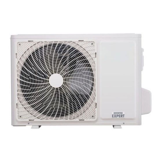
3. Product Picture and Drawing 3-1. Product Pictures Indoor units: Front Panel 09-18K View Front Panel View Outdoor Units:... - Page 11 09-12K 18-24K Capacity (Btu) View Remote controller:...
- Page 12 4056861 Model View...
-
Page 13: Product Dimensions
3-2. Product dimensions Indoor units: Model W (mm) H (mm) D (mm) ABHEM4H4S09 ABHEM4H4S12 ABHEM4H4S18 1130 ABHEM4H4S24 1290... -
Page 14: Outdoor Units
Outdoor units: Model (mm) (mm) (mm) (mm) (mm) (mm) (mm) ABHCI4H4S09 ABHCI4H4S12 ABHCI4H4S18 ABHCI4H4S24 Note: “ ** ” mean code of Front Panel. -
Page 15: Installation Instruction
4. Installation Instruction To prevent abnormal heat generation and the possibility of fire, do not place obstacles, enclosures and grilles in front of or surrounding the air conditioner in a way that may clock air flow. And, more than 1 meter away from any antenna or power lines or connecting wires used for TV, radio, telephone, security system, or intercom. - Page 16 * If total tubing length becomes 5 to 15 m (max.), charge additional refrigerant as the table1 for reference. And no additional compressor oil is necessary. Outdoor unit △ Heat sources, exhaust fans, etc. Avoid: △ Damp, humid or uneven locations. △...
- Page 17 Recommended Wire Diameter:...
-
Page 18: Electric Wiring Diagram
4-2. Electric Wiring Diagram Model Indoor Unit DIAGRAM Outdoor Unit DIAGRAM ABHCI/EM4H4S09 1984907 1854707 ABHCI/EM4H4S12 1984907 1854707 ABHCI/EM4H4S18 1984907 1854707 ABHCI/EM4H4S24 2146248 1854707 Note: “ ** ” mean code of Front Panel. 1984907 2146248... - Page 19 Outdoor: 1854707...
-
Page 20: Refrigerant Flow System
4-3. Refrigerant Flow System NOTE: In different models, the throttle assembly may be Capillary or Electronic expansion valve. -
Page 21: Air Purging And Leakage Test
4-4. Air Purging and Leakage Test 1. Connect charging hose of manifold valve to charge end of low pressure valve (both high/low pressure valves must be tightly shut). 2. Connect joint of charging hose to vacuum pump. 3. Fully open the handle of Lo manifold valve. 4. -
Page 22: Test Running
4-5. Test Running △ Check after Installation Items to be checked Possible malfunction Has it been fixed firmly? The unit may drop, shake or emit noise. Have you done the refrigerant leakage test? It may cause insufficient cooling(heating)capacity Is heat insulation sufficient? It may cause condensation and dripping. -
Page 23: Function Operation
5. Function Operation 5-1. Operation Range (cooling and heating) Temperature Cooling operation Heating operation 90℉(32℃) 81℉(27℃) Indoor temperature 70℉(21℃) 45℉(7℃) 115℉(46℃) 75℉(24℃) outdoor temperature 5℉(-15℃) -22℉(-30℃) *Optimum performance will be achieved within these operating temperature. If air conditioner is used outside of the above conditions, the protective device may trip and stop the appliance. -
Page 24: Remote Controller Operation & Function
5-2. Remote Controller Operation & Function △ Remote Controller Instruction 4056861... -
Page 25: Function Instruction
△ Function Instruction 1.Major general technical parameters 1-1 Remote receiver distance(front of the air conditioner): 8 m. 1-2 Remote receiver angle: Less than 60 degrees. 1-3 Temperature control accuracy: ±1℃(1°F). 1-4 Time error: Less than 1%.、 2. Functions of the controller 2-1 Display panel I. - Page 26 3-3 Timer function Real time of Timer setting (1) The max Timer ranges is 24 hours. (2) Timer ON/OFF (3) Timer ON/OFF can be set available in turn. (4) The Timer accurate more than 97% (5) The Timer can be adjusted by 1 min increase. (6) The appliance can be set the ON-Timer and OFF-Timer in the same time, but no any timer setting indicated.
- Page 27 is set to LOW and the fan speed can be adjusted After the appliance start the smart operation, the setting temperature can be adjusted 2℃ or 7℃ (based on the remote mode)(the min accuracy is 1℃) up and down base on the automatic temperature setting, also the presetting temperature of PCB circuit.
- Page 28 3-7 Heating-run mode 3-7-1 Temperature compensation The temperature compensation is 5º in heating mode. For example, if the set temperature is 25℃(77°F) by the remote control, when the room temperature is detected with 31℃(88°F), the compressor will turn off. The main reason is that the hot air is condensed at the top of the house.
- Page 29 The setting temperature - 2℃ MEDIAN The setting temperature - 4℃ High When the difference between the setting temperature and the room temperature equal to 2℃ or 4℃, the indoor fan speed will keep in current speed. 3-7-3 Air flow direction control The horizontal louver is controlled by a step motor, press the SWING button to swing or stop the louver.
-
Page 30: Special Function Instruction
Dehumidifying area I: Operation at the frequency in the range (30–60Hz) according to Dt (T indoor ambient-Test). f(Hz) Dt(℃) ≥2 Dehumidifying area II: The compressor stops for 5 minutes and operators for 5 minutes at the lowest frequency. Dehumidifying area III: The compressor stops. 3-10 Fan Only Mode Operation During the appliance run in this mode, the compressor and outdoor fan stop, the indoor fan operate under the pre-setting of air volume, and the louver swing, and the indoor fan speed same as the Heating Mode. - Page 31 frequency rising temperature”. Either of the above two conditions is met, the product will enter anti-freezing prohibition of frequency rising state. Anti-freezing prohibition of frequency rising operation: the compressor is kept at the current frequency, which may decrease according to situations while cannot rise. The outdoor fan runs. Condition for the end of anti-freezing prohibition of frequency rising state: when the temperature of indoor heat exchanger rises to “anti-freezing releasing temperature”, the state of anti-freezing prohibition of frequency rising is released.
-
Page 32: Electrical Characteristics
6. Electrical Characteristics 6-1. Print Circuit Board (Indoor & Outdoor) Model Print Circuit Board of Indoor unit Print Circuit Board of outdoor unit ABHCI/EM4H4S09 2157689 2127255 ABHCI/EM4H4S12 2157689 2127255 ABHCI/EM4H4S18 2157689 2127255 ABHCI/EM4H424 2201230 2127255 Note: “ ** ” mean code of Front Panel 、... - Page 33 Model of outdoor unit: 2127255 Terminal of Terminal of compressor 4-way valve DRED function compressor U/V/W phase terminal(BLACK) overload (OPTIONAL) (RED/WHITE/BLUE) protector(RED) Terminal of reactor wire Heater Over pressure Display tool terminal(RED) sensor(OPTIONAL) terminal(WHITE) (BROWN/ORANGE) Terminal of live wire, Outdoor ambient Terminal of DC/AC EEPROM program connect to the terminal...
-
Page 34: Temperature Sensor
6-3. Temperature Sensor Parameter table attached: 1. THE PARAMETER OF THE INDOOR COIL AND INDOOR ROOM SENSOR ,THE PARAMETER OF THE OUTDOOR COIL AND OUTDOOR ENVIRONMENT SENSOR: (R(0)=15k B(0/100)=3450) Resistance(k) Voltage(V) Resistance(k) Voltage(V) Temperature(℃) Temperature(℃) 38.757 0.58143512 4.292 2.715076661 36.844 0.60795346 4.137 2.76063657... - Page 35 7.051 2.09859271 1.213 4.039284017 6.778 2.14682606 1.177 4.062450215 6.516 2.19524793 1.142 4.085229093 6.267 2.24333597 1.109 4.106941536 6.028 2.29151689 1.076 4.12888601 2.33944954 1.045 4.149715216 5.581 2.38741691 1.015 4.17007359 5.372 2.43506494 0.986 4.189944134 5.172 2.48247664 0.957 4.210004953 4.981 2.52951096 0.93 4.228855721 4.797 2.57653834 0.904 4.247168554...
- Page 36 138.696 0.23368340 2.328767123 132.086 0.24480509 7.546 2.369998606 125.833 0.25634646 7.301 2.411176512 119.916 0.26831655 7.065 2.452217815 114.315 0.28072493 6.843 2.492120501 109.01 0.29358432 6.624 2.532777116 103.984 0.30690352 6.414 2.573028606 99.222 0.32068816 6.212 2.612972641 94.708 0.33494897 6.017 2.652726847 90.427 0.34969710 5.829 2.692216328 86.366 0.36494000 5.648 2.731362468...
-
Page 37: Compressor
6-4. Compressor Drawings attached: OVERLOAD PROTECTION INVERTER POWER & CONTROLLER Test in resistance. TOOL: Multimeter. Test the resistance of the winding. The compressor is fault if the resistance of winding 0(short circuit)or∞(open circuit) Familiar trouble: 1)Compressor motor lock. 2)Discharge pressure value approaches static pressure value .3)Compressor motor winding abnormality. -
Page 38: Trouble Shooting
7.Trouble Shooting 7-1. Error Code Table 1.Indication on the outdoor unit: When the unit has the following trouble and the compressor stops running, The LED of outdoor control board will show the error sequence automatically: ★: NOTE: LIGHT FLASH × :... - Page 39 Compressor a. the compressor exhaust temperature sensor is exhaust ★ failure; × temperature too b. the refrigerant of the unit is not enough high protection a. the outdoor ambient temperature sensor Outdoor ambient connect loose; ★ ★ temperature b. the outdoor ambient temperature sensor is ×...
- Page 40 a. the PFC is failure; PFC protection × × b. the outdoor drive board is failure Compressor pre ★ it is normal mode in cold weather heating process Chip in outdoor a. Using the wrong drive board; ★ × board in trouble b.
- Page 41 ★ ★ Frequency decreasing prohibition × frequency rising caused by anti-freezing of refrigeration or anti-overload in heating ★ ★ Frequency decreasing prohibition × frequency rising caused by too high compressor discharge temperature ★ ★ ★ Operation at fixed frequency (in the case of capability measuring or compulsory operation at fixed frequency) Protective frequency decreasing against outdoor...
- Page 42 a. The outdoor temperature sensor loose; The failure for temperature sensor b. the outdoor temperature sensor is failure; of outdoor coil c. The indoor control board is failure a. the compressor exhaust temperature sensor connect loose; Compressor exhaust temperature sensor b.
- Page 43 Compressor shell a. the compressor exhaust temperature sensor connect loose temperature too high b. the refrigerant of the unit is not enough protection a. the indoor coil temperature sensor connect loose; Anti-freeze protection b. the indoor coil temperature sensor is failure; with cooling or c.
- Page 44 The failure for a. The indoor coil temperature sensor loose; temperature sensor b. The indoor coil temperature sensor is failure; of indoor coil c. The indoor control board is failure. temperature a. the communication cable connect loose; b. the communication cable is failure; c.
-
Page 45: Test The Jumper Terminals
7-2. Test the jumper terminals Note: When the whole machine is powered up, if the external unit does not work, to rule out the communications failures, adopt screening method such as short circuit on the jumper terminals to see if the external unit can be started normally or similar method. - Page 46 compressor and outdoor fan stop, but indoor fan runs normally. Condition for ending over-current protection: when the current drops below “current value for releasing the refrigeration current protection (E2 value)”, over-current protection will be released. 2.Frequency decreasing for over-current Conditions for over-current frequency decreasing: if the current is equal to or greater than “current value for starting the refrigeration current protective frequency decreasing (E2 value)”, over-current frequency decreasing starts.
-
Page 47: Trouble Diagnosis Of Compressor
7-4. Trouble Diagnosis of Compressor Judging the connecting terminals of inverter compressor: It is impossible to identify terminals U, V and W of inverter compressor with multi-meter. Just connect the terminals in the same way as the original unit when replacing the compressor. A wrong connection will lead to reverse and loud noise of the compressor. - Page 48 Switch on the power supply Does it receive the Is the remote Does the screen remote controller controller display normally? signal? setting right? Is the fuse (5A/250V) burn? Check the code Is the remote controller in good Replace the batteries condition? Are the wires Make sure all wires...
- Page 49 Error code 9 Maximum current protection Is the windings of the Compressor conpressor right or fault,replace the not(each winding and compressor winding to the earth) The outdoor control board fault,replace the board...
- Page 51 Error code 16 cooling mode Anti-freeze protection indoor unit Is indoor heat Check the coil Change the indoor exchanger iced up? sensor right or not board Change the coil Refrigeration system protection,check the sensor air inlet and outlet of indoor unit Error code 16 heating mode Overload protection indoor unite Is indoor heat...
- Page 52 DC fan motor test point:...
- Page 53 Error code 33 Take out the red Indoor connector temperature sensor.Measure the Does the resistance sensor resistance of sensor Replace the of the sensor have indoor control the characteristics on board Take out the white sensor parameter Error code 34 connector Indoor Coil sensor.Meaure the...
- Page 54 Error code 19 Compressor drive in trouble Is fastening screw fastening of IPM fastened? Check the wiring Corrent the connection between main or replace the wires control board and connectors and compressor Change the control Check the board or replace it Replace the fan or the Check the outdoor fan is outdoor unit...
- Page 55 test point: Forward of IPM P-U/P-V/P-W test : Reverse of IPM P-U/P-V/P-W test: Forward of IPM N-U/N-V/N-W test : Reverse of IPM N-U/N-V/N-W test :...
- Page 56 test point: The resistance of the compressor U-W\V-W Error code 36 Communication trouble Is the order of all wires including the indoor and Adjust the order of wires outdoor unit correct? Are all lead wires connecting Retighten the wires connecting indoor and outdoor unit indoor and outdoor unit loosen loosen?
Need help?
Do you have a question about the Blue HYPER ABHCI/EM4H4S09 and is the answer not in the manual?
Questions and answers