
Related Manuals for Nokia IP290 - Security Appliance


Summary of Contents for Nokia IP290 - Security Appliance
-
Page 1: Installation Guide
Nokia IP290 Security Platform Installation Guide Part No. N450000746 Rev 001 Published August 2008... - Page 2 IMPORTANT NOTE TO USERS This software and hardware is provided by Nokia Inc. as is and any express or implied warranties, including, but not limited to, implied warranties of merchantability and fitness for a particular purpose are disclaimed. In no event shall Nokia, or its affiliates, subsidiaries or suppliers be liable for any direct, indirect, incidental, special, exemplary, or consequential damages (including, but not limited to, procurement of substitute goods or services;...
- Page 3 Singapore 119968 Nokia Customer Support Web Site: https://support.nokia.com/ Email: tac.support@nokia.com Americas Europe Voice: 1-888-361-5030 or Voice: +44 (0) 125-286-8900 1-613-271-6721 Fax: 1-613-271-8782 Fax: +44 (0) 125-286-5666 Asia-Pacific Voice: +65-67232999 Fax: +65-67232897 050602 Nokia IP290 Security Platform Installation Guide...
- Page 4 Nokia IP290 Security Platform Installation Guide...
-
Page 5: Table Of Contents
About the Nokia IP290 Security Platform ....... . . 15... - Page 6 Before You Begin ..........57 Replacing a Nokia Encryption Accelerator Card ......60 Before You Begin .
- Page 7 Table 4 NIC PCI Frequency ........39 Nokia IP290 Security Platform Installation Guide...
- Page 8 Nokia IP290 Security Platform Installation Guide...
- Page 9 Figure 8 Power Switch Location ........33 Figure 9 Nokia Network Voyager Reference Access Points ....37 Figure 10 Two-Port Copper Gigabit Ethernet NIC Front Panel .
- Page 10 Nokia IP290 Security Platform Installation Guide...
-
Page 11: About This Guide
About this Guide This guide describes how to install and use the Nokia IP290 security platform. Installation and maintenance should be performed by experienced technicians or Nokia-approved service providers only. This preface provides the following information: In This Guide Conventions This Guide Uses... -
Page 12: Conventions This Guide Uses
Notes provide information of special interest or recommendations. Command-Line Conventions Table 1 describes the elements of commands that are available in Nokia business security products. You might encounter one or more of the following elements in a command-line path. Table 1 Command-Line Conventions... -
Page 13: Text Conventions
Related Documentation You can find this guide in PDF on the Nokia support Web site (https:// support.nokia.com/) and on the Nokia IPSO operating system CD-ROM issued with your Nokia IP290 security platform. Nokia IP290 Security Platform Installation Guide... - Page 14 CLI Reference Guide for the version of Nokia IPSO you are using Getting Started Guide and Release Notes for the version of Nokia IPSO you are using Nokia IPSO Boot Manager Reference Guide, which describes how to use the Nokia IPSO...
-
Page 15: Overview
Overview This chapter provides an overview of the Nokia IP290 security platform and the requirements for using the appliances. The following topics are covered: About the Nokia IP290 Security Platform on page 15 Nokia IP290 Appliance Overview on page 15... -
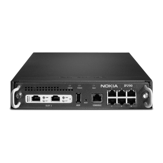
Page 16: Built-In Gigabit Ethernet Ports
Reset switch Console port Figure 2 Component Locations Rear View Fan vent Power plug 00558 Power switch Built-in Gigabit Ethernet Ports Figure 3 shows the layout of the six built-in 10/100/1000 Ethernet ports and their LEDs. Nokia IP290 Security Platform Installation Guide... -
Page 17: Console Port
1, to establish a modem connection for managing the appliance remotely or out-of-band. Use USB cables with a standard USB A-style connector and pinout for the AUX port. For Nokia approved modem connections, you will need a USB to RS232 adaptor. -
Page 18: System Status Leds
Overview Note The only modem approved for use with Nokia security appliances with USB AUX ports is the Radicom model V92MB-U-E, and you must be using Nokia IPSO 6.1 or greater. System Status LEDs You can monitor the basic operation of Nokia IP290 appliances by checking their status LEDs. -
Page 19: Site Requirements
No recognizable boot device with a valid kernel found. Kernel panic (followed in 20 seconds by CPU reset). Site Requirements Before you install a Nokia IP290 appliance, ensure that your computer room or wiring closet conforms to the environmental specifications listed in Appendix A, “Technical Specifications.”... -
Page 20: Safety Warnings And Cautions
Managing Nokia IP290 Appliances You can manage Nokia IP290 appliances by using one of the following interfaces: Nokia Network Voyager—an SSL-secured, Web-based element management interface to Nokia IP security platforms. Network Voyager is preinstalled on the IP290 appliance and enabled through the IPSO operating system. - Page 21 Everything that you can accomplish with Nokia Voyager—to manage and configure the IP290 appliance—you can also do with the CLI. For information about how to access the CLI, see the Nokia CLI Reference Guide for the version of IPSO you are using.
- Page 22 Overview Nokia IP290 Security Platform Installation Guide...
-
Page 23: Installing The Nokia Ip290 Appliance
Installing the Nokia IP290 Appliance You can rack mount Nokia IP290 appliances in the following ways: A single appliance in a one-unit space (1U) or in a two-appliance shell with the second appliance space covered by a filler panel. Two appliances in a 1U space in a two-appliance shell. -
Page 24: Rack Mounting A Single Nokia Ip290 Appliance
RE SET CO NS OL E 00614a Rack Mounting a Single Nokia IP290 Appliance Before you mount the appliance on the rack, install the two side brackets with four screws on each side as shown in Figure 6. The brackets and screws are included with the materials you receive with the appliance. -
Page 25: Figure 6 Installing The Mounting Brackets
Rack Mounting a Single Nokia IP290 Appliance Figure 6 Installing the Mounting Brackets ST A T U S P O W FA U SL O IP 2 A U X RE SE CO N SO LE Bracket position A ST A... -
Page 26: Rack Mounting Two Nokia Ip290 Appliances Side-By-Side
00560 Rack Mounting Two Nokia IP290 Appliances Side-by-Side The following procedure describes how to install two Nokia IP290 appliances in a 1U rack space. This method does not allow you to change the position of the mounting brackets, as you can when you use the single-appliance installation method. - Page 27 Rack Mounting Two Nokia IP290 Appliances Side-by-Side Note The procedure assumes that you are using an empty shell, but it might be populated with one or two appliances when you receive your product depending on what was ordered from the factory.
- Page 28 To remove the appliance, use a screwdriver to turn the locking latch counterclockwise until you cannot turn it with light force. To secure the appliance To release the appliance 00562 Nokia IP290 Security Platform Installation Guide...
- Page 29 Rack Mounting Two Nokia IP290 Appliances Side-by-Side The following figure shows how the installation appears if you are using two appliances side-by-side in a 1U space. 00564 Nokia IP290 Security Platform Installation Guide...
- Page 30 Installing the Nokia IP290 Appliance Nokia IP290 Security Platform Installation Guide...
-
Page 31: Performing The Initial Configuration
Network Interface Cards.” Connecting to the Console Port If you do not use DHCP to perform the initial configuration of your Nokia IP290 appliance, you must use a serial console connection (RJ-45 null-modem cable included). After you perform the initial configuration, the console connection is no longer required. -
Page 32: Connecting Power And Turning The Power On
Connecting Power and Turning the Power On A power switch and a receptacle for the power cord are located on the power on the back of the appliance as shown in Figure Nokia IP290 Security Platform Installation Guide... -
Page 33: Figure 8 Power Switch Location
To reduce stress on the power supply, after you turn the appliance on, wait at least ten seconds before you turn it off. Likewise, after you turn the power supply off, wait at least ten seconds before you turn it back on. Nokia IP290 Security Platform Installation Guide... -
Page 34: Performing The Initial Configuration
Power is turned on to the power strip or wall receptacle into which you plugged the appliance. If the fan is still not running, or if the power LED does not illuminate, contact your Nokia service provider as listed in “Nokia Contact Information”... -
Page 35: Connecting Network Interfaces
Enter. For more information about how to respond to the prompts during the initial configuration process, see the Getting Started Guide and Release Notes for the version of Nokia IPSO you are using. 5. After you complete the initial configuration, you can use Network Voyager to configure the remaining network ports. -
Page 36: Using Nokia Network Voyager
Network Voyager interface, as shown in Figure Nokia Network Voyager Reference Guide—This guide is the comprehensive reference source for Nokia Network Voyager. To access this source, look at the list in the navigation tree on the left side of the window (as shown in Figure 9).You can also access the Nokia... -
Page 37: Using The Command-Line Interface
Link to inline help (context sensitive help) Using the Command-Line Interface You can also use the Nokia IPSO command-line interface (CLI) to manage and configure Nokia IP290 appliances from the command line. Everything that you can accomplish with Network Voyager you can also do with the CLI. -
Page 38: Using Nokia Horizon Manager
Performing the Initial Configuration You can now execute CLI commands from the CLI shell and the Nokia IPSO shell. The Nokia IPSO shell is what you see when you initially log on to the appliance. Execute from To Implement Purpose... -
Page 39: About Ip290 Appliance Network Interface Cards
About IP290 Appliance Network Interface Cards This chapter describes the network interface cards (NICs) available for the Nokia IP290 appliance and how to connect those NICs to your network. The following NICs are described: Two-Port Copper Gigabit Ethernet NIC Two-Port Fiber-Optic Gigabit Ethernet NICs For instructions about how to add or replace NICs, see Chapter 5, “Installing and Replacing... -
Page 40: Copper Gigabit Ethernet Nic Features In The Ip290
Note The two-port copper Gigabit Ethernet NIC you use in IP290 appliances must be the Version 2 type, as indicated on the right end of the NIC faceplate. These NICs are sold by Nokia under the order code NIF4425. After the power is turned on and the cables are connected, the Ethernet Link LEDs on both the appliance and on the remote equipment illuminate to indicate the connection. -
Page 41: Copper Gigabit Ethernet Nic Connectors And Cables
11, the RJ-45 cable output connector is numbered from right to left, with the copper pins facing up and toward you. Figure 11 Gigabit Ethernet Cable Connector Pin Assignments 1000 Mbps 10/100 Mbps Pin# Assignment Assignment BI_DA+ 00270 BI_DA- BI_DB+ BI_DC+ BI_DC- BI_DB- BI_DD+ BI_DD- Nokia IP290 Security Platform Installation Guide... -
Page 42: Two-Port Fiber-Optic Gigabit Ethernet Nics
To connect the appliance to other network components, you can order appropriate adapter cables separately from a cable vendor of your choice. Two-Port Fiber-Optic Gigabit Ethernet NICs The IP290 appliance supports Nokia-approved, two-port, fiber-optic Gigabit Ethernet NICs installed in the PMC expansion slot. The IP290 appliance can accommodate one Gigabit Ethernet NIC. -
Page 43: Fiber-Optic Gigabit Ethernet Nic Connectors And Cables
The long-range single-mode fiber (SMF) fiber-optic Gigabit Ethernet NICs in the IP290 run on Nokia IPSO v4.2 or higher. You can configure and monitor Gigabit Ethernet NIC interfaces with Nokia Network Voyager. Specifically, you set the port speed and full-duplex mode with Network Voyager. - Page 44 Gigabit Ethernet NICs. You can order additional cables from a cable vendor of your choice. Cables that connect to the Gigabit Ethernet NIC must be IEEE 802.3z compliant to prevent potential data loss. Nokia IP290 Security Platform Installation Guide...
-
Page 45: Installing And Replacing Network Interface Cards
Deactivating Configured Interfaces If you are removing or replacing an installed NIC, use Nokia Network Voyager to deactivate any configured ports on the NIC before removing it. Deactivate all of the logical interfaces on the NIC. -
Page 46: Installing Nics
To install a network interface card 1. Use Nokia Network Voyager or command-line interface (CLI) to perform an orderly shutdown of the IP290 appliance. For information about how to access Network Voyager and the related reference materials, “Using Nokia Network Voyager”... - Page 47 5. Slide the chassis tray assembly forward, and completely remove the chassis to expose the motherboard components. ST AT PO W FA U SL O IP 2 AU X RE SE CO N SO LE 00563 6. Place the chassis tray assembly on a table top. Nokia IP290 Security Platform Installation Guide...
- Page 48 C O N S O L 00570 If you are installing a NIC in an unoccupied slot, remove the blank bezel that occupies the space in the appliance front panel and retain it for future use. Nokia IP290 Security Platform Installation Guide...
- Page 49 S L O I P 2 A U X R E S C O N S O L 00572 Make sure that the NIC edge is completely seated into the connectors on the chassis tray assembly. Nokia IP290 Security Platform Installation Guide...
- Page 50 A U X R E S C O N S O L 00571 10. From beneath the chassis tray assembly, screw in the bezel retaining screws. 11. Slide the chassis tray assembly back into the appliance. Nokia IP290 Security Platform Installation Guide...
-
Page 51: Configuring And Activating Interfaces
The IP290 appliance automatically detects any new NIC when the appliance is restarted. Use Nokia Network Voyager to configure and activate the logical and physical interfaces on the NIC. For information about how to access Network Voyager and the related reference materials, see “Using Nokia Network Voyager”... - Page 52 Installing and Replacing Network Interface Cards Nokia IP290 Security Platform Installation Guide...
-
Page 53: Installing And Replacing Components Other Than Network Interface Cards
(NICs) in your appliance. The following topics are covered: Installing a Hard-Disk Drive Replacing or Upgrading Memory Replacing a Nokia Encryption Accelerator Card Replacing the Battery For information about how to add or replace NICs, see Chapter 5, “Installing and Replacing Network Interface Cards.”... -
Page 54: Before You Begin
If you fail to use the following procedure when you remove the hard-disk drive, the drive might become damaged or you might lose data. 1. Use Nokia Network Voyager or the command-line interface (CLI) to perform an orderly shutdown of the IP290 appliance. - Page 55 Figure 5 on page 24. ST AT PO W FA UL SL OT IP 2 AU X RE SET CO N SO LE 00563 6. Place the chassis tray assembly on a table top. Nokia IP290 Security Platform Installation Guide...
-
Page 56: Replacing Or Upgrading Memory
The appliance has two dual inline memory-module (DIMM) sockets that are double data rate (DDR2), which perform at high speed. This section describes how to upgrade or replace the memory by using a Nokia-approved memory upgrade kit. Nokia IP290 Security Platform Installation Guide... -
Page 57: Before You Begin
To upgrade or replace your appliance memory, you need: Physical access to the appliance Nokia memory upgrade kit Access to the appliance by using Nokia Network Voyager or command-line interface (CLI) A Phillips-head screwdriver Grounding wrist strap Nokia IP290 Security Platform Installation Guide... - Page 58 To replace DIMMs 1. Use Nokia Network Voyager or the command-line interface (CLI) to perform an orderly shutdown of the appliance. For information about how to access Network Voyager and the related reference materials, “Using Nokia Network Voyager”...
- Page 59 The top of the DIMM is smooth. The bottom edge has two different-length sets of contacts, which mate with the slots on the socket. Be sure the contacts and slots are properly aligned before you insert the DIMM. Nokia IP290 Security Platform Installation Guide...
-
Page 60: Replacing A Nokia Encryption Accelerator Card
VPN performance. The IP290 appliance uses a PMC format accelerator card. The accelerator card has no external connections and requires no cables. The accelerator card software package is part of Nokia IPSO, so the appliance automatically detects and configures the card. -
Page 61: Before You Begin
To install the accelerator card 1. Use Nokia Network Voyager or the command-line interface (CLI) to perform an orderly shutdown of the IP290 appliance. For information about how to access Network Voyager and the related reference materials, “Using Nokia Network Voyager”... - Page 62 7. Position the male PMC connector on the card over the female PMC connector on the motherboard. The connectors should be aligned with each other. The three screw holes and three standoffs should also be aligned with each other. Nokia IP290 Security Platform Installation Guide...
- Page 63 Replacing a Nokia Encryption Accelerator Card 8. Push down on the card until it is properly seated on the motherboard. 00568 9. Place the screws through the standoff holes on the card and into the standoffs on the motherboard. Screw...
-
Page 64: Configuring Software To Use Hardware Acceleration
The Nokia encryption accelerator software package is part of the Nokia IPSO operating system, so the appliance automatically detects and configures the Nokia encryption accelerator card. For the Nokia IP290 appliances, SecureXL is on by default. After you install the Nokia encryption accelerator card and reboot the appliance, SecureXL automatically uses the Nokia encryption accelerator card for encryption acceleration. - Page 65 To install the battery 1. Use Nokia Network Voyager or the command-line interface (CLI) to perform an orderly shutdown of the IP290 appliance. For information about how to access Network Voyager and the related reference materials, “Using Nokia Network Voyager”...
- Page 66 For details, see Figure 5 on page 24. ST AT PO W FA UL SL OT IP 2 AU X RE SET CO N SO LE 00563 6. Locate the battery on the motherboard. Nokia IP290 Security Platform Installation Guide...
- Page 67 Caution You must place the new battery into the battery holder observing the correct polarity. 9. Slide the chassis tray assembly back into the appliance. 10. Resecure the two chassis tray assembly retaining screws. Nokia IP290 Security Platform Installation Guide...
- Page 68 When you resecure the chassis tray assembly retaining screws, do not exceed a torque of 4.5 inch-pounds. 11. Replace the power cord. 12. Turn on the power. After you replace the battery, you need to reset the date and time using Network Voyager or the CLI. Nokia IP290 Security Platform Installation Guide...
-
Page 69: Troubleshooting
This chapter provides troubleshooting tips, problems, and solutions related to Nokia IP290 appliance installations. General Troubleshooting Information The information in this section relates to problems you might encounter during the Nokia IP290 appliance installation. Appliance Not Receiving Power Problem Power cord is not properly plugged in. - Page 70 “Nokia Contact Information” page 3. Login Prompt Appears, But Password Not Accepted Problem Database is corrupt Solution Return to default settings or contact the Nokia customer support site listed in “Nokia Contact Information” on page 3. Problem Entered wrong password.
- Page 71 This procedure erases any configuration database on the appliance. For information about how to complete the full installation procedure, see the current release notes. The release notes are located on the Nokia customer support Web site as listed in the “Nokia Contact Information”...
- Page 72 Troubleshooting Problem High collision rate on the hub. Solution Disconnect connections one at a time until the problem is localized to one computer and troubleshoot further. Nokia IP290 Security Platform Installation Guide...
-
Page 73: A Technical Specifications
23.6 lbs. (10.7 kg) shell containing two base systems Space Requirements Nokia IP290 appliances are designed for front-screw mounting in a 19-inch rack. Each IP290 appliance requires the following space in a rack: 1.6 inches (4.1 centimeters) of vertical space for a single appliance 1.7 inches (4.3 centimeters) of vertical space for appliances in a shell... -
Page 74: Other Specifications
To 10, 000 feet or 3300 meters above sea level ° Operating temperature range 41 to 104 Fahrenheit ° 5 to 40 Celsius Input voltage requirement 115 VAC or 220 VAC, 50 or 60 Hz Current Power consumption 35 watts Nokia IP290 Security Platform Installation Guide... -
Page 75: B Compliance Information
IEC 60950-1:2001 EN 60950-1:2001+A11 EMC: EN55024 1998, EN55022A 1998, EN61000-3-2, EN61000-3-3 Supplementary information: Pursuant to ISO/IEC 17050 this product complies with the requirements of the Low Voltage Directive 73/23/EEC and the EMC Directive 2004/108/EC. Nokia IP290 Security Platform Installation Guide... -
Page 76: Compliance Statements
FCC Part 15 Subpart B Class A US/Canada EN55022 (CISPR 22) Class A European Community (CE) Immunity Standards EN55024 European Community (CE) EN61000-4-2 EN61000-4-3 EN61000-4-4 EN61000-4-5 EN61000-4-6 EN61000-4-11 Harmonics and Voltage Fluctuation EN61000-3-2 European Community (CE) EN61000-3-3 European Community (CE) Nokia IP290 Security Platform Installation Guide... -
Page 77: Fcc Notice (Us)
Caution Any changes or modifications not expressly approved by the grantee of this device could void the user’s authority to operate the equipment. 050316 Nokia IP290 Security Platform Installation Guide... - Page 78 Compliance Information Nokia IP290 Security Platform Installation Guide...
-
Page 79: Index
32 monitoring 18 copper Gigabit Ethernet NIC 39, 41 cryptographic processing 60 LC connector 43, 44 data communications equipment device 32 deactivating, network interface cards 45 DHCP server, initial configuration 31 Nokia IP290 Security Platform Installation Guide Index - 79... - Page 80 PMC expansion slots 45 power connections 32 random access memory 57 recycling retired equipment 19 retaining clips, DIMM 60 serial port 17 single-mode, fiber-optic cable 44 specifications space requirements 73 standoffs, motherboard 63 Index - 80 Nokia IP290 Security Platform Installation Guide...
- Page 81 We Welcome Your Comments Nokia is interested in improving our documentation to better serve our customers. Please feel free to send comments and suggestions to docfeedback@nokia.com. If you are using Adobe Acrobat Reader 6.0 or later, we invite you to provide feedback to us by using the following form.
Need help?
Do you have a question about the IP290 - Security Appliance and is the answer not in the manual?
Questions and answers