Table of Contents
Advertisement
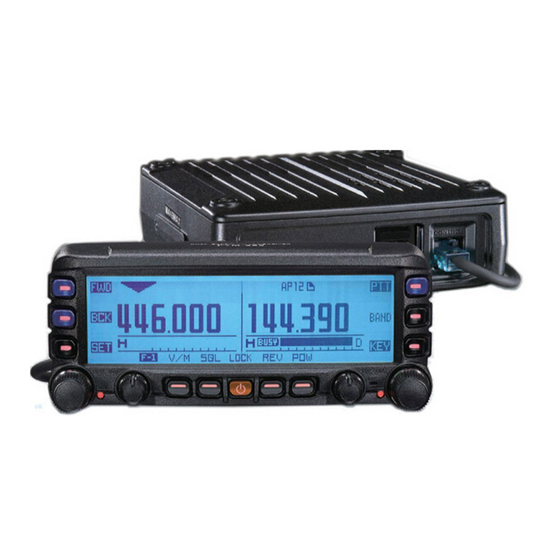
DUAL BAND FM TRANSCEIVER
FTM-350 S
O
M
VERTEX STANDARD CO., LTD.
4-8-8 Nakameguro, Meguro-Ku, Tokyo 153-8644, Japan
VERTEX STANDARD
US Headquarters
10900 Walker Street, Cypress, CA 90630, U.S.A.
YAESU UK LTD.
Unit 12, Sun Valley Business Park, Winnall Close
Winchester, Hampshire, SO23 0LB, U.K.
VERTEX STANDARD HK LTD.
Unit 5, 20/F., Seaview Centre, 139-141 Hoi Bun Road,
Kwun Tong, Kowloon, Hong Kong
VERTEX STANDARD AUSTRALIA PTY., LTD.
Normanby Business Park, Unit 14/45 Normanby Road
Notting Hill 3168, Victoria, Australia
Advertisement
Table of Contents

Related Manuals for Yaesu FTM-350


Summary of Contents for Yaesu FTM-350
- Page 1 DUAL BAND FM TRANSCEIVER FTM-350 S VERTEX STANDARD CO., LTD. 4-8-8 Nakameguro, Meguro-Ku, Tokyo 153-8644, Japan VERTEX STANDARD US Headquarters 10900 Walker Street, Cypress, CA 90630, U.S.A. YAESU UK LTD. Unit 12, Sun Valley Business Park, Winnall Close Winchester, Hampshire, SO23 0LB, U.K.
-
Page 2: Table Of Contents
Front Panel Controls & Switches ......1 Internet Connection Feature ....... 20 SRG ( “Sister Radio Group” ) Mode ....22 Timer Page Operation ..........2 FRG ( “Friendly Radio Group” ) Mode ....21 Radio Page Basic Operation ........3 [ SMART FUNCTION ] Key ........ -
Page 3: Front Panel Controls & Switches
“on” and “off”. [ FUNCTION ] key, the current the transceiver is turned on function of these keys will to toggle the key lockout change and the function will feature on or off. appear above each key. FTM-350 S... -
Page 4: Timer
To return to the “Radio” page, press the [ FWD ] or [ BCK ] To return to the “Radio” page, press the [ FWD ] or [ BCK ] key repeatedly, until the “Radio” Page appears. key repeatedly, until the “Radio” Page appears. FTM-350 S... -
Page 5: Radio Page Basic Operation
Rotate the [ DIAL ] knob to select the operating frequency. Press and hold the [ PTT ] key, and speak into the microphone in a normal voice level. Press and hold the [ POWER ] key for two seconds to turn the transceiver off. FTM-350 S... -
Page 6: Smart Function ] Key
SMART FUNCTION K The FTM-350 Series Transceiver operations are performed using the [ SMART FUNC- TION ] keys. The various functions of the keys are changed by pressing the [ F ] key. [ SMART FUNCTION ] key [ FUNCTION ] key Pressing the [ F ] key repeatedly will change the function command of each [ SMART FUNC- TION ] key as shown in the following tables. -
Page 7: Smart Function ] Key Command Details
Toggles the transceiver power “on and “off”. Press Key Selects the DCS code. D COD Press & Hold Key No Action. Press Key Selects the User Programmed Reverse CTCSS Tone frequency.. P FRQ Press & Hold Key No Action. FTM-350 S... -
Page 8: Memory Operation
On rare occasions the stored data may become corrupted by miss operation, or static electricity. When repairs are made, the memory data may be lost. Please write down or record the memory information so you will be able to restore it if needed. FTM-350 S... -
Page 9: Storing Independent Transmit Frequency
[ V/M ] key for two seconds. Rotate the left side [ DIAL ] knob to select the same memory channel number as used in step 1 above. Press the [ TXIN ] key to store the independent transmit frequency into memory. FTM-350 S... -
Page 10: Memory Recall
When a “Tagged” memory channel is displayed with the Alpha/numeric “Tag”, a small frequency indication will also be shown. You may change the display between “Tag” indication and “Frequency” indication via Set Mode item “D01 MEMORY DISPLAY” in the “MEMORY” group. FTM-350 S... -
Page 11: Memory Edit
1. Rotate the left side [ DIAL ] knob to select the memory channel to delete. 2. Press the [ SEL ] key. The selected column will blink. 3. Press the [ DEL ] key to delete the memory channel data. FTM-350 S... -
Page 12: Memory Channel Sort
If you decide to cancel the memory channel sort, press the [ ESC ] key. 5. Press the left side [ DIAL ] knob again. After several seconds, sorting is complete, and the transceiver will reset automatically. FTM-350 S... -
Page 13: Af Dual Operation
Press the [ AD-F ] key to disable the AF Dual function and return to normal operation. When operating with APRS or Operating Frequency Baud Rate Packet on the left side band, the operating frequency and baud rate of the APRS or Packet op- eration will appear on the dis- play. FTM-350 S... -
Page 14: Band Scope Operation
Press the [ STOP ] key to stop the sweep of the Band Scope temporarily, if desired. Press the [ START ] key to start the sweep of the Band Scope again. Press the “main” band [ DIAL ] knob to disable the Band Scope and return to normal operation. FTM-350 S... -
Page 15: Enhanced Mode
4. Press the left side [ DIAL ] knob, and then rotate the left side [ DIAL ] knob to select “SPECIAL”. 5. Press the left side [ DIAL ] knob to save the new setting. 6. Press the [ ESC ] key, the transceiver is reset automatically. FTM-350 S... -
Page 16: Ctcss/Dcs/Epcs Operation
When operating the APRS with the Voice Alert function (see page 79 on the FTM- 350 Series APRS Manual for details), the CTCSS frequency/DCS code which is set on the left side band will replace the CTCSS frequency/DCS code which is set by the Voice Alert function automatically. FTM-350 S... -
Page 17: Epcs Operation
4. To end the EPCS operation, press the [ TYPE ] key repeatedly, until the “OFF” notation appears. You may customize the EPCS operation so that a ringing “bell” sound alerts you when a EPCS call is received. Use Set Mode item “J01 BELL RINGER” in the “SIGNALING” group. See page 45 for details. FTM-350 S... -
Page 18: Scan Operation
You may customize the functions of the Memory Scan using Set Mode items “D03 MEMORY SCAN TYPE” in the “MEMORY” group, “D04 MEMORY SKIP/SELCT”, “F03 SCAN RESUME”, “F04 SCAN STOP BEEP” in the “SCAN” group, and “G08 RX COVERAGE” in the “SYSTEM” group. FTM-350 S... -
Page 19: Programmable Memory Scan ( Pms )
4. Press the [ DW ] key again to stop the Dual Watch feature. You may customize the functions of the Dual Watch feature via Set Mode items “F01 DUAL WATCH STOP” and “F03 SCAN RESUME” in the “SCAN” group. FTM-350 S... -
Page 20: Operation
7. If the pairing is successful (requires 20 to 30 seconds), the “PAIRING OK !” notation will appear on the display. The transceiver will turn off and back on again. ® Headset is correctly recognized by the FTM-350 Series Trans- When the ®... -
Page 21: Operation
® Charge the battery of the Headset. In the factory default setting of the FTM-350 Series Transceiver, the internal and external speakers, the front panel microphone, and front panel MIC jack are all disabled when the ® Headset is correctly recognized. However, the microphone connected to the transceiver’s MIC jack is still alive. -
Page 22: Internet Connection Feature
The FTM-350 Series Transceiver can be used to access a “node” (repeater or base station), which is tied into the Vertex Standard WiRES™ (Wide-Coverage Internet Repeater En- hancement System) network, operating in the “SRG” (Sister Radio Group) mode. Details may be found at the WiRES-II Web site: http://www.vxstd.com/en/wiresinfo-en/. -
Page 23: Frg ( "Friendly Radio Group" ) Mode
4) Press the [ ] key (located at the left edge of the [ SMART FUNCTION ] key while transmitting) while pressing the PTT switch to transmit the access code. 5. To disable the Internet Connection feature, select the “OFF” selection in the Set Mode item “J06 WiRES”. FTM-350 S... -
Page 24: Srg ( "Sister Radio Group" ) Mode
5. To disable the DTMF Autodialer, select the “OFF” selection in the Set Mode item “J06 DTMF MODE”. You may send a telephone number by pressing the microphone numeric keys ([ 1 ] through [ 9 ]) corresponding to the DTMF memory string you wish to send. FTM-350 S... -
Page 25: Baro/Alti
The FTM-350 Series Transceiver can display the current Barometric Pressure and relative changes in the pressure. Furthermore, when an optional FGPS-1 or FGPS-2 GPS Unit is installed, the FTM-350 Series Transceiver can display the current altitude and relative changes in the altitude. -
Page 26: Gps Operation
“G10 UNIT SELECT” in the “SYSTEM” group (see page 42), and also change the time format via Set Mode item “I02 DATE&TIME FORMAT” in the “TIMER/CLOCK” group (see page 44). : The FGPS-2 GPS Antenna Unit requires CT-133 GPS Antenna Cable and CT-136 GPS Antenna Adapter. FTM-350 S... - Page 27 GPS A “Point” memory The FTM-350 Series Transceiver has 16 “point” memories (four channels in each of four groups), which store the position (Longitude/Latitude) and the date. When your vehicle nears one of the “Point” memories, the “Nav” pop-up window will open for ten seconds even if another page is being displayed.
- Page 28 You may acquire your current position (Longitude/Latitude) from an aftermarket GPS receiver by connecting an aftermarket GPS receiver to the DATA jack, and setting Set Mode item “E16 COM PORT SETTING” in the “APRS/PKT” group to “GPS IN”. See page 72 on the APRS manual for details. FTM-350 S...
- Page 29 FTM-350 S...
-
Page 30: Navi Operation
GPS A The FTM-350 Series Transceiver enables navigating to any destination previously entered into the “Point” memory. Furthermore, you may enable navigating to the location of an- other APRS station by using the APRS feature. See page 32 in the APRS manual for details. - Page 31 ] key to move the cursor. 6. Press the [ ENT ] key to overwrite the setting. 7. Press the [ NAVI ] key to return to the “NAVI” Page, then press the [ NAVI ] key again to initiate navigation. FTM-350 S...
-
Page 32: Audio Playback Operation
The FTM-350 Series Transceiver can record an incoming signal. The recording mode has two types; (a) automatic recording of the last 30 seconds of incoming signal (“Last” mode), or (b) eight recording memories of variable length (“Free” mode; capable of storing up to five minutes of total recording time). - Page 33 FTM-350 S...
-
Page 34: Miscellaneous Setting ( Set Mode Operation )
The FTM-350 Series Transceiver has 89 items in the Set Mode, and they are arranged in 8 groups (A-K). It is convenient to initially select the group by rotating the left side [ DIAL ] knob. Then briefly press the left side [ DIAL ] knob and rotate it again to select the desired operating item. -
Page 35: Audio Group
FRONT+REAR: Receiver audio is routed through the FRONT (located in the front panel) and REAR (located in the transceiver body) speakers. FRONT: Output the receiving audio from the FRONT speaker. OFF: Disable the FRONT and REAR speakers. REAR: Output the receiving audio from the REAR speaker. FTM-350 S... - Page 36 RX MUTE: Disables the sub band’s receiver audio output when receiving a signal on the main band. TRX MUTE: Disables the sub band’s receiver audio output while transmitting on the main band, and when receive the signal on the main band. FTM-350 S...
-
Page 37: Tx/Rx Group
[ B ] key (center key on the right edge of the display). 108 - 137 MHz band 174 - 250 MHz band 300 - 400 MHz band 480 - 999.9875 MHz bands (Cellular blocked) FTM-350 S... - Page 38 B08: WIDE / NARROW AUTO Function: Selects the receiving mode. Available Values: AUTO, WIDE FM, FM, NARROW FM, or AM Default: AUTO B09: WX ALERT Function:Enables/Disables the weather alert scan feature. Available Values: ON or OFF Default: OFF FTM-350 S...
-
Page 39: Display Group
Function: Selects the displays backlight color. Available Values: WHITE-BLUE, SKY-BLUE, MARINE-BLUE, GREEN, YELLOW-GREEN, ORANGE, UMBER or WHITE Default: SKY-BLUE C04: LCD CONTRAST Function: Sets the display’s contrast level. Available Values: MIN, 2, 3, 4, 5, 6, 7, or MAX Default: 4 FTM-350 S... -
Page 40: Memory Group
Function: Selects the “scan flag” to the current memory channel. Available Values: OFF, SKIP, or SELECT Default: OFF OFF: All memory channels will be scanned SKIP: The current memory channel is set to scan “SKIP” channel. SELECT: The current memory channel is set to scan “SELECT” channel. FTM-350 S... -
Page 41: Scan Group
TIME 5 sec: The scanner will hold on a signal it encounters, and scanner will resume after five seconds. F04: SCAN STOP BEEP Function: Enables/Disables the scan stop beep. Available Values: ON or OFF Default: OFF FTM-350 S... -
Page 42: System Group
Activates the PA (Public Address) function which sends your voice audio (microphone input) to the transceiver’s speaker. SQL OFF: Disables the SQL temporarily. T-CALL: Activates a 1750 Hz burst tone, used for repeater access in many countries (especially in Europe). WiRES: Recalls the WiRES memory. FTM-350 S... - Page 43 Recalls the Weather channel. G07: OPERATION MODE Function: Shifting of CPU clock frequency. Available Values: A or B Default: A This Set Mode item is only used to move a spurious response “birdie”, should it fall on a desired frequency. FTM-350 S...
- Page 44 RX mode automatically. Available Values: OFF, 5 min, 10 min, 15min, 20 min, or 30 min Default: OFF G10: UNIT SELECT Function: Selects the measurement units of the environment sensor. Available Values: METER or YARD-POUND Default: YARD-POUND FTM-350 S...
-
Page 45: Navi Group
Available Values: 0.05 mile, 0.1 mile, 0.2 mile, 0.3 mile, 0.5 mile, 1.0 mile, or 2.0 mile Default: 0.1 mile H03: NAVI POPUP Function: Selects the “NAVI” Pop-up function. Available Values: OFF, 1 sec ~ 30 sec, or CONTINUOUS Default: 10 sec FTM-350 S... -
Page 46: Timer/Clock Group
I03: TIME SIGNAL Function: Enables/Disables the Timer Signal “on” and “off”. Available Values: OFF or ON Default: OFF I04: TIME ZONE Function: Sets the time offset between local time and UTC. Available Values: UTC–14:00 ~ UTC+14:00 (0.5H/step) Default: UTC±0:00 LONDON FTM-350 S... -
Page 47: Signaling Group
8. Press the [ ENT ] key to save the setting. J03: DTMF MODE Function: Enables/Disables the DTMF autodialer feature. See page 22 for details. J04: PAGER CODE Function: Sets the Pager Code for Enhanced CTCSS Paging & Code Squelch. See page 15 for details. FTM-350 S... - Page 48 J07: WiRES MEMORY Function: Selects the access number (DTMF digit) for SRG operation of the Internet Con- nection feature (WiRES Available Values: CODE 0 ~ CODE 9, CODE A ~ CODE D, CODE , or CODE # Default: CODE 1 FTM-350 S...
-
Page 49: Option Group
Headset. VOX PTT: Activates the Headset for use with the PTT circuit. VOX VOX HIGH: Activates the Headset with the VOX feature (VOX Gain: High). VOX VOX LOW: Activates the Headset with the VOX feature (VOX Gain: Low). FTM-350 S... - Page 50 Disables the Voice Guide feature (Audio Playback feature only). ANNOUNCE “MANUAL”: Announces the operating frequency of the “Main” band when the [ ENT ] key is pressed. ANNOUNCE “AUTO”: Announces the operating frequency of the “Main” band when the operating band is changed. FTM-350 S...
-
Page 51: Cloning
The FTM-350 Series Transceiver includes a convenient “Clone” feature, which allows the memory and configuration data from one transceiver to be transferred to another FTM-350 Series Transceiver. This can be particularly useful when configuring a number of transceiv- ers for a public service operation. Here is the procedure for Cloning one radio’s data to another: 1. -
Page 52: Installation
Avoid heating vents and window locations that could expose the transceiver to excessive direct sunlight, especially in hot climates. This transceiver should not be used in an environment where the ambient temperature exceeds +140 °F (+60 °C). FTM-350 S... -
Page 53: Safety Information
Do not connect the modular connector of the telephone line to MIC jack. Warning!: High RF voltage is present in the TX RF section of the transceiver while transmitting. Do not touch the TX RF section while transmitting. FTM-350 S... -
Page 54: Special Function Menu
( OK? [ SET ]) is displayed on the LCD. Press the left side [ DIAL ] knob once more to complete the reset procedure. (To cancel the reset procedure, press the [ ESC ] key before pressing the left side [ DIAL ] knob.) FTM-350 S... -
Page 55: Accessories & Options
Control Cable (3 m) ......................1 Speaker Cable ........................1 Spare Fuse (15 A, 32 V) ..................... 1 FTM-350 Series Operating Manual ................... 1 FTM-350 Series APRS Manual ..................1 Connection and Setting Manual ..................1 Warranty Card ........................1... -
Page 56: Specification
Panel + Rear Chassis + Connection Cable Specifications are subject to change without notice, and are guaranteed within the 144/ 222/430 MHz amateur bands only. Cellular Blocked per FCC rule Part 15.121, may not receive 900 MHz Amateur band. FTM-350 S... - Page 57 12 kHz / 30 kHz (–6 dB / –60 dB) 8 W @ 4 Ω for 10 % THD (@ 13.8 V) BTL EXP SP AF Output: 4 W @ 4 Ω for 10 % THD (@ 13.8 V) Normal EXP SP 4-16 Ω AF Output Impedance: FTM-350 S...
-
Page 58: Fcc Notice
The Scanner receiver is not a digital scanner and is incapable of being converted or modified to a digital scanner receiver by any user. : MODIFICATION OF THIS DEVICE TO RECEIVE CELLULAR RADIOTELEPHONE SERVICE SIGNALS IS PROHIBITED UNDER FCC RULES AND FEDERAL LAW. FTM-350 S... - Page 60 Copyright 2010 Printed in Japan VERTEX STANDARD CO., LTD. All rights reserved. No portion of this manual may be reproduced without the permission of VERTEX STANDARD CO., LTD.
Need help?
Do you have a question about the FTM-350 and is the answer not in the manual?
Questions and answers