Yaesu FTM-300DR Instruction Manual
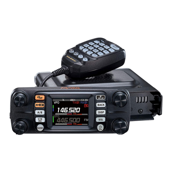
Dual band digital transceiver
Hide thumbs
Also See for FTM-300DR:
- Operating manual (80 pages) ,
- Advance manual (65 pages) ,
- Technical supplement (59 pages)

Related Manuals for Yaesu FTM-300DR


Summary of Contents for Yaesu FTM-300DR
- Page 1 C4FM/FM 144/430MHz DUAL BAND DIGITAL TRANSCEIVER FTM-300DR FTM-300DE Instruction Manual (GM Edition)
-
Page 2: Table Of Contents
Contents What is the GM Function? ..................... 2 GM Operation ........................3 Display the APL (Automatic Position Locating) screen ..........4 Confirm the location of a Group Member station in real time ........5 Display the position of the member station on the compass screen ......5 Registering the Location Information of a Partner Station .......... -
Page 3: What Is The Gm Function
What is the GM Function? The GM (Group Monitor) function automatically monitors on the same frequency for any other stations with the GM function in operation, or stations operating in DN mode, within communication range. The GM function then displays the acquired direction and distance information for each detected call sign on the screen. -
Page 4: Gm Operation
GM Operation 1. Tune to the frequency used by the group that you would like to communicate with. • If you only want to check your group location information, press and hold the [GM] key and set the send and receive DG-ID numbers to the same numbers except “00” at all the partner stations. -
Page 5: Display The Apl (Automatic Position Locating) Screen
Display the APL (Automatic Position Locating) screen The positions of up to four group stations are displayed on the APL (Automatic Position Locating) screen, centered on your own station. The direction and progress of each sta- tion is displayed, and you can check each other's position, distance, and moving direc- tion. -
Page 6: Confirm The Location Of A Group Member Station In Real Time
Confirm the location of a Group Member station in real time The position of the selected member can be confirmed in real time on the compass screen. The member's current position may be registered as the navigation destination. Display the position of the member station on the compass screen 1. -
Page 7: Registering The Location Information Of A Partner Station
Registering the Location Information of a Partner Station You can register the current position of the selected member, and then navigate toward that station. 1. Press the [GM] key. JA1YOE-0AB 2. Rotate the DIAL knob to select the station for which you want to registering location information. -
Page 8: Checking Received Messages And Images
Checking Received Messages and Images Use the GM function to check the messages and images on the LOG list. When using a GM function, a beep sounds when a new message or image is received, and the “LOG MSG” or “LOG PICT” list screen (see step 3 below) appears automatically. 1. - Page 9 press the DIAL knob to reply to the sender of the downloaded message or image data. Refer to “Replying to the Sender of the Checked Message or Image Data” (page 12). • Press the [F(SETUP)] key, then rotate the DIAL knob to select [DEL], then press the DIAL knob to display “DELETE?”.
-
Page 10: Sending Massages Or Images
Sending massages or images There are 4 ways to send messages or images using the GM function: (1) Creating and sending a new message (2) Replying to the sender of the checked message or image data (3) Forwarding the checked message or image data (4) Sending your snapshot images Creating and sending a new message Create and send a new message:... -
Page 11: Using Standard Messages
6. Refer to “Text input screen” in the FTM-300DR/DE Operating Manual to enter a message. • Rotate the DIAL knob to select [MTXT], then press the DIAL knob to easily input a message using a standard form. • In the message input screen, one line is displayed for every 20 characters. Rotate... -
Page 12: Registering A Standard Message
3. Rotate the DIAL to select the standard message you ||||||||||||| want to use. ||||||||||||| 4. Press the DIAL knob. ||||||||||||| ||||||||||||| ||||||||||||| ||||||||||||| 5. The entire message is displayed. |||||||||||||||| To add letters to the message, input letters following steps 6 in “Creating and sending a new message”... -
Page 13: Replying To The Sender Of The Checked Message Or Image Data
Replying to the Sender of the Checked Message or Image Data After checking the message or image data, you may reply to the sender. 1. Select the information (MESSAGE or PICT) to review according to steps 1 to 4 of “Checking Received Messages and Images”... -
Page 14: Sending Your Snapshot Images
Sending Your Snapshot Images Take still images using the optional speaker microphone with built-in snapshot camera (MH-85A11U) and send them to the group members. For details on how to send images taken with the optional speaker microphone built- in snapshot camera (MH-85A11U), refer to “Taking Picture (Snapshot Function)” in FTM- 300DR/DE Operating Manual. -
Page 15: Gm Set Mode List
When communicating with another transceiver, if the DP-IDs of the sta- tions are registered in both transceivers, they can communicate even though the DG-ID numbers are different. For details, refer to the FTM-300DR/DE operating Manual. z 2 RANGE RINGER Explanation: Activates/deactivates the alert sound when detecting stations within com- munication range. - Page 16 Copyright 2020 YAESU MUSEN CO., LTD. All rights reserved. No portion of this manual may be reproduced without the permission of YAESU MUSEN CO., LTD. YAESU MUSEN CO., LTD. Tennozu Parkside Building 2-5-8 Higashi-Shinagawa, Shinagawa-ku, Tokyo 140-0002 Japan YAESU USA 6125 Phyllis Drive, Cypress, CA 90630, U.S.A.
Need help?
Do you have a question about the FTM-300DR and is the answer not in the manual?
Questions and answers