Table of Contents
Advertisement
Quick Links
Download this manual
See also:
User Manual
Advertisement
Table of Contents

Related Manuals for Delta Tau 5xx-603869-xUxx


Summary of Contents for Delta Tau 5xx-603869-xUxx
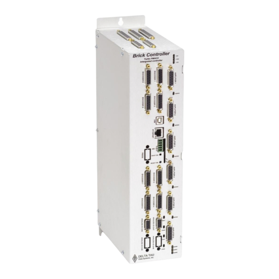
- Page 1 HARDWARE REFERENCE MANUAL Single Source Machine Control 21314 Lassen Street Chatsworth, CA 91311 // Tel. (818) 998-2095 Fax. (818) 998-7807 // www.deltatau.com Brick Motion Controller Programmable Servo Amplifier 5xx-603869-xUxx May 2, 2007 Power // Flexibility // Ease of Use...
-
Page 2: Copyright Information
© 2007 Delta Tau Data Systems, Inc. All rights reserved. This document is furnished for the customers of Delta Tau Data Systems, Inc. Other uses are unauthorized without written permission of Delta Tau Data Systems, Inc. Information contained in this manual may be updated from time-to-time due to product improvements, etc., and may not conform in... - Page 3 After removing the power source from the equipment, wait at least 10 minutes before touching or disconnecting sections of the equipment that normally carry electrical charges (e.g., capacitors, contacts, screw connections). To be safe, measure the electrical contact points with a meter before touching the equipment.
- Page 5 REV. DESCRIPTION MANUAL CREATION REVISION HISTORY DATE 05/02/07 APPVD S. MILICI...
-
Page 7: Table Of Contents
125 ... I Copyright Information... ii Operating Conditions ... ii Safety Instructions... ii INTRODUCTION ...1 Brick Motion Controller Features ...1 SPECIFICATIONS ...3 Part Number ...3 Brick Motion Controller Options...3 RECEIVING AND UNPACKING ...5 Use of Equipment...5 SYSTEM WIRING...7 Noise Problems...7 Wiring Earth-Ground ...7 Earth Grounding Paths...7 Connectors...8... - Page 8 APPENDIX B...38 Schematics...38 X15: Watchdog ...38 J6 and J7: General Purpose I/O...38 J4: Limit Inputs for Axis 1-4 ...40 J5: Limit Inputs for Axis 5-8 ...41 Dimensional Layout and Connector location ...42 Table of Contents...
-
Page 9: Introduction
INTRODUCTION The Brick Motion Controller is a fully scaleable automation controller utilizing the intelligence and capability of its embedded Turbo PMAC2. With the ability to store programs locally and built-in PLC execution, it is programmable for virtually any kind of automation application. This allows for complete machine motion and logic control. - Page 10 • Primary encoder for each axis with TTL differential/single-ended inputs with A, B quadrature channels and C index channel, 10 MHz cycle rate, and digital Hall-effect inputs • Five flags per axis using DB-25: HOME, PLIM, MLIM and USER inputs; EQU compare •...
-
Page 11: Specifications
SPECIFICATIONS Part Number CPU Options - Turbo PMAC 2 Processor C0 : 80Mhz, 8Kx24 Internal, 256Kx24SRAM, 1MB Flash (Default) F3: 240Mhz, 192Kx24 Internal, 1Mx24SRAM, 4MB Flash Number of Axes BC4 - C0 - F00 - 000 – (0000) 4: Four Axes (Default) 8: Eight Axes Axis 5-8 Feedback Options , apply only to BC4 controller Note: For Other Feedback Options See “Special Feedback Options”... -
Page 12: Communication Options
Analog I/O Options • Two 16-bit analog inputs • Four 16-bit analog inputs Communication Options • DPRAM option, size 32K x 16-bit wide (required for use with NC software) • ModBus Ethernet Communication Protocol (Software) option • DPRAM and Modbus options combined •... -
Page 13: Receiving And Unpacking
RECEIVING AND UNPACKING Delta Tau products are thoroughly tested at the factory and carefully packaged for shipment. When the Brick Motion Controller is received, there are several steps that should be performed immediately: 1. Observe the condition of the shipping container and report any damage immediately to the commercial carrier that delivered the drive. - Page 14 Brick Motion Controller Hardware Reference Manual Specifications...
-
Page 15: System Wiring
SYSTEM WIRING Installation of electrical control equipment is subject to many regulations including national, state, local, and industry guidelines and rules. General recommendations can be stated but it is important that the installation be carried out in accordance with all regulations pertaining to the installation. Noise Problems When problems do occur often it points to electrical noise as the source of the problem. -
Page 16: Connectors
Connectors X1-X8: Encoder Input (1 to 8) The main encoder input channels for the Brick Motion Controller support only differential quadrature feedback. 5V supply to power the encoder is provided. • 4-axis drives with no Option 01 or Option 02 have only X1 to X4, for a total of four encoders Option 01 adds two extra S. -
Page 17: X9-10: Analog I/O Ch5 (X9) And Ch6 (X10), (Optional)
X9-10: Analog I/O Ch5 (X9) and Ch6 (X10), (Optional) X9/10 (Female DB-9 Connector) Pin # Symbol AGND ADC5/6+ ADC5/6- For spacing specifications between the DB- connectors, see Appendix A of this manual. X11-12: Analog I/O Ch7 (X11) and Ch8 (X12), (Optional) X11/12 (Female DB-9 Connector) Pin # Symbol... -
Page 18: X13: Usb 2.0 Connector
X14: RJ45, Ethernet Connector This connector is used for Ethernet communications from the Geo PMAC Drive to a PC. Delta Tau Systems strongly recommends the use of RJ45 CAT5e or better shielded cable. Newer network cards have the Auto-MDIX feature that eliminates the need for crossover cabling by performing an internal crossover when a straight cable is detected during the auto-negotiation process. -
Page 19: Tb1: Power Connector
TB1: Power Connector The TB1 connector at the bottom panel allows the user to supply 24V DC power for the Brick Controller. Watchdog (TB1) (Phoenix 3-pin Terminal Block) Pin # Symbol +24VDC Chassis GND +24V return S1: Re-Initialization on Reset Control Hold switch in during power cycle for PMAC re-initialization. -
Page 20: J4 Limit Inputs (1-4 Axis)
J4 Limit Inputs (1-4 Axis) The Brick Motion Controller limit and flag circuits give the flexibility to wire in standard 12V to 24V limits and flags or wire in 5V level limits and flags on a channel basis. The default is set for the standard 12V to 24V inputs, but if the resistor pack is added to the circuit, the card can read 5V inputs. -
Page 21: J5 Limit Inputs (5-8 Axis)
J5 Limit Inputs (5-8 Axis) The Brick Motion Controller limit and flag circuits give the flexibility to wire in standard 12V to 24V limits and flags or wire in 5V level limits and flags on a channel basis. The default is set for the standard 12V to 24V inputs, but if the resistor pack is added to the circuit, the card can read 5V inputs. - Page 22 A sample of the positive limit circuit is shown below. The 4.7K resistor packs used will allow 12-24V flag inputs. If 0-5V flags are used, then a 1KΩ resistor pack (RP) can be placed in: Flags 1-4: RP39 (channel 1), RP43 (channel 2), RP 47 (channel 3), RP51 (channel 4) Flags 5-8: RP89 (channel 5), RP93 (channel 6), RP 97 (channel 7), and RP 101 (channel 8).
-
Page 23: Amp1-Amp8: Amplifier Connections (1 To 8)
AMP1-AMP8: Amplifier connections (1 to 8) AMP1-AMP8 Amplifier connections (1-8) (Female DB-15 Connector) Symbol Function DACnA+ Output DACnB+ Output AE_NCn+ Output AE_NOn+ Output AFAULTn- Input N.C. N.C. AGND Common DACnA - Output DACnB - Output AE_COMn Common AFAULTn+ Input N.C. AGND Common N.C. - Page 24 Brick Motion Controller Hardware Reference Manual Amplifier Fault / Amplifier Enable diagrams System Wiring...
-
Page 25: J6: General Purpose I/O
J6: General Purpose I/O General purpose I/O is available on the Brick Motion Controller. All I/O is electrically isolated from the drive. Inputs can be configured for sinking or sourcing applications. All Inputs are 12-24VDC. All Outputs are 24V nominal operation, 0.5A maximum current. Outputs are robust against ESD and overload. -
Page 26: Suggested M-Variable Addressing For The General Purpose I/O (J6)
Suggested M-Variable Addressing for the General Purpose I/O (J6) Suggested M-var. # Address M0-> Y:$78800,0,1 M1-> Y:$78800,1,1 M2-> Y:$78800,2,1 M3-> Y:$78800,3,1 M4-> Y:$78800,4,1 M5-> Y:$78800,5,1 M6-> Y:$78800,6,1 M7-> Y:$78800,7,1 M8-> Y:$78801,0,1 M9-> Y:$78801,1,1 M10-> Y:$78801,2,1 M11-> Y:$78801,3,1 M12-> Y:$78801,4,1 M13-> Y:$78801,5,1 M14->... -
Page 27: J7: Extra General Purpose I/O (Optional)
J7: Extra General Purpose I/O (Optional) General purpose I/O is available on the Brick Motion Controller. All I/O is electrically isolated from the drive. Inputs can be configured for sinking or sourcing applications. All Inputs are 12-24VDC. All Outputs are 24V nominal operation, 0.5A maximum current. Outputs are robust against ESD and overload. -
Page 28: Suggested M-Variable Addressing For The Optional General Purpose I/O (J7)
Suggested M-Variable Addressing for the optional General Purpose I/O (J7) Suggested M-var. # Address M40-> Y:$78803,0,1 M41-> Y:$78803,1,1 M42-> Y:$78803,2,1 M43-> Y:$78803,3,1 M44-> Y:$78803,4,1 M45-> Y:$78803,5,1 M46-> Y:$78803,6,1 M47-> Y:$78803,7,1 M48-> Y:$78804,0,1 M49-> Y:$78804,1,1 M50-> Y:$78804,2,1 M51-> Y:$78804,3,1 M52-> Y:$78804,4,1 M53->... -
Page 29: J8: Extra General Purpose I/O (Optional)
J8: Extra General Purpose I/O (Optional) General purpose I/O is available on the Brick Motion Controller. All I/O is electrically isolated from the drive. Inputs can be configured for sinking or sourcing applications. All Inputs are 12-24VDC. All Outputs are 24V nominal operation, 0.5A maximum current. Outputs are robust against ESD and overload. -
Page 30: Suggested M-Variable Addressing For The General Purpose I/O (J8)
Suggested M-Variable Addressing for the General Purpose I/O (J8) Suggested M-var. # Address M64-> Y:$78A00,0,1 M65-> Y:$78A00,1,1 M66-> Y:$78A00,2,1 M67-> Y:$78A00,3,1 M68-> Y:$78A00,4,1 M69-> Y:$78A00,5,1 M70-> Y:$78A00,6,1 M71-> Y:$78A00,7,1 M72-> Y:$78A01,0,1 M73-> Y:$78A01,1,1 M74-> Y:$78A01,2,1 M75-> Y:$78A01,3,1 M76-> Y:$78A01,4,1 M77-> Y:$78A01,5,1 M78->... - Page 31 Sample J6/J7, I/O Wiring Diagrams Sourcing 01-16 Inputs Sourcing 01-08 Outputs GPIN01 GPIN02 GPIN03 Inputs GPIN04 GPIN05 01-08 GPIN06 GPIN07 GPIN08 GPIN09 GPIN10 GPIN11 Inputs GPIN12 GPIN13 09-16 GPIN14 GPIN15 GPIN16 IN_COM_01-08 IN_COM_09-16 COM_COL Output 01 GPO1- GPO2- Output 02 GPO3- Output 03 GPO4-...
-
Page 32: Setting Up Quadrature Encoders
Setting up Quadrature Encoders Digital quadrature encoders are the most common position sensors used with Geo Drives. Interface circuitry for these encoders comes standard on board-level Turbo PMAC controllers, UMAC axis- interface boards, Geo drives, and QMAC control boxes. Signal Format Quadrature encoders provide two digital signals that are a function of the position of the encoder, each nominally with 50% duty cycle, and nominally one-quarter cycle apart. -
Page 33: Encoder Loss Setup
Encoder Loss Setup The Brick Motion Controller has encoder-loss detection circuitry for each encoder input. Designed for use with encoders with differential line-driver outputs, the circuitry monitors each input pair with an exclusive-or (XOR) gate. If the encoder is working properly and connected to the Brick Motion Controller, the two inputs of the pair should be in opposite logical states –... -
Page 34: Setting Up The Analog Inputs (Optional)
Brick Motion Controller Hardware Reference Manual For more details about Encoder Loss look into the Turbo USERs Manual chapter: Making Your Application Safe. Setting up the Analog Inputs (optional) The Brick Motion Controller can be ordered with two or four 16-bit hi-resolution analog to digital converters. - Page 35 etc.), then writing values to the M-variable. The analog outputs are intended to drive high-impedance inputs with no significant current draw. The 220Ω output resistors will keep the current draw lower than 50 mA in all cases and prevent damage to the output circuitry, but any current draw above 10 mA can result in noticeable signal distortion.
- Page 36 hardware clock signals are SCLK (encoder sample clock), PFM_CLK (pulse frequency modulator clock), DAC_CLK (digital-to-analog converter clock), and ADC_CLK (analog-to-digital converter clock). Parameters to Set Up Per-Channel Hardware Signals I70n6 is the output mode; “n” is the output channel number (i.e. for channel 1 the variable to set would be I7016, I7026 for channel 2 etc.).
-
Page 37: Setting Up For Pulse And Direction Output
Setting up for Pulse and Direction Output The following section shows how to quickly setup the key variables for a stepper motor (PFM) system. The step and direction outputs are RS422 compatible and are capable of being connected in either differential mode or single ended configurations for 5V input drivers. -
Page 38: Single-Channel I-Variables
I7m04: PFM Pulse Width Control The pulse width is specified in PFM clock cycles and has a range of 1 to 255 cycles. The default value is 15. Since the default value of PFM clock is actually set to 9.8304 MHz, the default output pulse width will be 15/9,830400 = 1.5258 µS. - Page 39 Ixx30: Motor xx Proportional Gain To create a closed loop position response with a natural frequency of approximately 25 Hz and a damping ratio of 1, use the following calculation: Example: PFMCLK is set to default of 9.83 MHz, and Ixx08 is set to default of 96. Ixx30 = 660,000 / (96 * 9.83) = 700.
- Page 40 Example: User wants channels 5 to 8 to be used with stepper motors. First the user needs to wire the Stepper drive, and so as to enable the Stepper output pin 8 needs to be shorted to pin 4 (+5V) for X5 to X8.
-
Page 41: Actions On Watchdog Timer Trip
Watchdog Timer Brick Motion Controller has an on-board watchdog timer. This subsystem provides a fail-safe shutdown to guard against software and hardware malfunction. To keep it from tripping the hardware circuit for the watchdog timer requires that two basic conditions be met. First, it must see a DC voltage greater than approximately 4.75V. - Page 42 • Disconnect any accessories and cables other than the logic power and repeat to see if they are causing the problem • Check for adequate 24V power supply levels (check at the Brick Motion Controller connector side, not at the supply) •...
-
Page 43: Appendix A
APPENDIX A DB- Connector Spacing Specifications X1-8: DB-15 Connectors for encoder feedback 1.541±.015 X9-12: DB-9 Connectors for Analog I/O 1.213+.015 Screw Lock Size for all DB-connectors #4-40 FEMALE SCREWLOCK QTY 2 per connector QTY 2 per connector Steel, Zinc Plated Appendix A 3.115±.05 2.45±.05... -
Page 44: Type Of Cable For Encoder Wiring
Therefore, the following recommendations are based upon some experiences that we at Delta Tau Data Systems have acquired. If possible, the best cabling to use is a double-shielded twisted pair cable. Typically, there are four pairs used in a differential encoder’s wiring. - Page 45 Brick Motion Controller User Manual – Preliminary Documentation Note: If noise is a problem in the application, careful attention must be given to the method of grounding that is used in the system. Amplifier and motor grounding can play a significant role in how noise is generated in a machine. Noise may be reduced in a motor-based system by the use of inductors placed between the motor and the amplifier.
-
Page 46: Appendix B
APPENDIX B Schematics X15: Watchdog NC7SZ08M5 (SOT23-5) J6 and J7: General Purpose I/O Inputs RP152 GPIN01 GPIN02 GPIN03 GPIN04 1.2KSIP8I MMBZ33VALT1 MMBZ33VALT1 MMBZ33VALT1 MMBZ33VALT1 RP158 GPIN05 GPIN06 GPIN07 GPIN08 1.2KSIP8I MMBZ33VALT1 MMBZ33VALT1 IN_COM_01--08 MMBZ33VALT1 MMBZ33VALT1 BWDO MMBD301LT1 (SOT23) FBR12ND05 Opto Gnd Plane MMBZ5V6ALT1 MMBZ5V6ALT1 MMBZ5V6ALT1... - Page 47 Outputs Opto Gnd Plane NZT560A (SOT-223) 2.2K ANO1 CAT1 NZT560A (SOT-223) ANO2 2.2K CAT2 ANO3 CAT3 ANO4 NZT560A CAT4 (SOT-223) PS2701-4 2.2K NZT560A (SOT-223) 2.2K NZT560A (SOT-223) 2.2K ANO1 CAT1 NZT560A (SOT-223) ANO2 2.2K CAT2 ANO3 CAT3 ANO4 NZT560A CAT4 (SOT-223) PS2701-4 2.2K...
-
Page 48: J4: Limit Inputs For Axis 1-4
J4: Limit Inputs for Axis 1-4 PS2705-4 C160 PS2705-4 C164 PS2705-4 C168 PS2705-4 C172 RP37 USER1 PLIM1 MLIM1 HOME1 FL_RT1 4.7KSIP8I RP38 4.7KSIP8I RP39 x1KSIP8I (IN SOCKET) C162 RP40 C161 C163 1KSIP8I RP41 USER2 PLIM2 MLIM2 HOME2 FL_RT2 4.7KSIP8I RP42 4.7KSIP8I RP43 x1KSIP8I... -
Page 49: J5: Limit Inputs For Axis 5-8
J5: Limit Inputs for Axis 5-8 PS2705-4 C200 C201 PS2705-4 C204 C205 PS2705-4 C208 C209 PS2705-4 C212 C213 Appendix C RP87 USER5 PLIM5 MLIM5 HOME5 FL_RT5 4.7KSIP8I RP88 4.7KSIP8I RP89 x1KSIP8I (IN SOCKET) C202 RP90 C203 1KSIP8I RP91 USER6 PLIM6 MLIM6 HOME6 FL_RT6... -
Page 50: Dimensional Layout And Connector Location
Brick Motion Controller Hardware Reference Manual Dimensional Layout and Connector location Appendix C...
Need help?
Do you have a question about the 5xx-603869-xUxx and is the answer not in the manual?
Questions and answers