Table of Contents
Advertisement
Quick Links
Advertisement
Table of Contents

Subscribe to Our Youtube Channel
Related Manuals for Delta Tau TURBO 4AX-603625-XUXX


Summary of Contents for Delta Tau TURBO 4AX-603625-XUXX
- Page 1 HARDWARE REFERENCE MANUAL UMAC-CPCI Turbo CPU Board Single Source Machine Control 21314 Lassen Street Chatsworth, CA 91311 // Tel. (818) 998-2095 Fax. (818) 998-7807 // www.deltatau.com Turbo CPU Board 4Ax-603625-xUxx January 28, 2003 Power // Flexibility // Ease of Use...
-
Page 2: Copyright Information
Copyright Information © 2003 Delta Tau Data Systems, Inc. All rights reserved. This document is furnished for the customers of Delta Tau Data Systems, Inc. Other uses are unauthorized without written permission of Delta Tau Data Systems, Inc. Information contained in this manual may be updated from time-to-time due to product improvements, etc., and may not... -
Page 3: Table Of Contents
UMAC-CPCI Turbo CPU Board Hardware Reference Manual INTRODUCTION ...1 Associated Manuals...2 BOARD CONFIGURATION ...3 Option 1: Communications Interfaces...3 Option 2: Dual-Ported RAM ...3 Option 5: CPU and Memory Configurations...3 Option 8: High-Accuracy Clock Crystal ...4 Option 9: Serial Port Configuration ...4 Option 10: Firmware Revision Specification ...4 Option 16: Battery-Backed Parameter Memory...4 HARDWARE SETUP ...5... - Page 4 UMAC-CPCI Turbo CPU Board J2 Connector ...18 J4: RS-232 Serial Port Connector...19 ACCESSORIES ...21 ACC-Cx Compact UBUS Backplane Boards...21 ACC-8CR Test Breakout Board...21 ACC-11C Sinking I/O Board ...21 ACC-24C2 PWM Axis Board...22 ACC-24C2A Analog Axis Board...22 ACC-51C Analog Encoder Interpolator Board ...22 SCHEMATICS ...23 UMAC-CPCI Turbo CPU Board Hardware Reference Manual Table of Contents...
-
Page 5: Introduction
UMAC-CPCI Turbo CPU Board Hardware Reference Manual INTRODUCTION Delta Tau’s UMAC-CPCI systems provide a compact and clean integration of motion and I/O control for sophisticated automation equipment. The system consists of a modular set of 3U-size (100mm x 160mm) boards in the “Compact PCI” format, implementing Turbo PMAC software and hardware functions, communicating with each other over a common backplane (the “Compact UBUS”). -
Page 6: Associated Manuals
UMAC-CPCI Turbo CPU Board Hardware Reference Manual Associated Manuals This document is the Hardware Reference Manual for the UMAC-CPCI Turbo CPU board for an UMAC- CPCI system. It describes the hardware features and provides setup instructions. You will need other manuals as well to use your UMAC-CPCI system. Each accessory to the UMAC- CPCI Turbo CPU board has its own manual, describing its operation and any required software setup of the Turbo CPU. -
Page 7: Board Configuration
UMAC-CPCI Turbo CPU Board Hardware Reference Manual BOARD CONFIGURATION The base version of the UMAC-CPCI Turbo CPU board provides a 1-slot 3U-format Eurocard board with: 80 MHz DSP56303 CPU (120 MHz PMAC equivalent) 128k x 24 SRAM compiled/assembled program memory (Opt. 5C0) 128k x 24 SRAM user data memory (Opt. -
Page 8: Option 8: High-Accuracy Clock Crystal
U19 and a “can-stack” lithium battery in component BT1. While the average expected battery life is over five years, a yearly replacement schedule is recommended. Replacement batteries can be ordered from Delta Tau as Acc-1LS (Part # 100-0QTC85-000). UMAC-CPCI Turbo CPU Board Hardware Reference Manual... -
Page 9: Hardware Setup
UMAC-CPCI Turbo CPU Board Hardware Reference Manual HARDWARE SETUP Clock-Source Jumpers In order to operate properly, the Turbo CPU board must receive servo and phase clock signals from a source external to the board. These clock signals can be brought into the board from one of three possible ports: the stack connector, the UBUS backplane connector, or the front-side main serial-port connector. -
Page 10: Serial-Port Level Select Jumpers
UMAC-CPCI Turbo CPU Board Hardware Reference Manual Serial-Port Level Select Jumpers The standard serial port can be used for either RS-232 or RS-422 serial communications. To use RS-232, jumpers E17 and E18 should connect pins 1 and 2; to use RS-422, jumpers E17 and E18 should connect pins 2 and 3. -
Page 11: Connections
UMAC-CPCI Turbo CPU board to communicate with axis and I/O boards through a common backplane board, such as a Delta Tau ACC-Cx board, or a user-designed backplane board. It also provides the 3.3V and 5V power supply lines to the CPU board. -
Page 12: Factory-Use Connectors
UMAC-CPCI Turbo CPU Board Hardware Reference Manual Factory-Use Connectors There are several connectors on the interior of the board for factory setup and diagnostic use. These are not for customer use. Connections... -
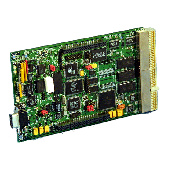
Page 13: Board Layout
UMAC-CPCI Turbo CPU Board Hardware Reference Manual BOARD LAYOUT This diagram of the UMAC-CPCI Turbo CPU board shows the locations of the jumpers and connectors. Detailed information about each of the jumpers and connectors follows. UMAC-CPCI Turbo CPU Board Layout Board Layout... - Page 14 UMAC-CPCI Turbo CPU Board Hardware Reference Manual Board Layout...
-
Page 15: Jumper Descriptions
UMAC-CPCI Turbo CPU Board Hardware Reference Manual JUMPER DESCRIPTIONS Pin 1 of an E-point is masked by an X and a bold square in white ink on the composite side, and by a square solder pad on the solder side. E0: Reset-Lock Enable (Factory Use Only) E Point &... -
Page 16: E3: Re-Initialization On Reset Control
E3: Re-Initialization on Reset Control E Point & Location Physical Layout E4: (Reserved for Future Use) E Point & Location Physical Layout E5: USB/Ethernet Communication Jumper E Point & Location Physical Layout E11: Power Supply Check Control E Point & Location Physical Layout E11:... -
Page 17: E18A, B, C, D: Ethernet Communication Control
UMAC-CPCI Turbo CPU Board Hardware Reference Manual E18A, B, C, D: Ethernet Communication Control E Point & Physical Location Layout E18D E18C E18B E19: Watchdog Disable Jumper E Point & Physical Location Layout E20 – E22: Power-Up/Reset Load Source E Point & Location Physical Layout E20:... -
Page 18: W1: Flash Ic Power Supply Select Jumper
W1: Flash IC Power Supply Select Jumper E Point & Location Physical Layout UMAC-CPCI Turbo CPU Board Hardware Reference Manual Description (Note: This jumper is set at the factory and possibly hard soldered. Users should not change this jumper.) Jump pin 1 to 2 to select 3.3V supply for flash memory IC in U10. Jump pin 2 to 3 to select 5V supply for flash memory IC in U10. -
Page 19: Connector Summary
UMAC-CPCI Turbo CPU Board Hardware Reference Manual CONNECTOR SUMMARY Compact UBUS Backplane Connector “Thru-Backplane” Field Wiring Connector RS-232 Front-Panel Serial-Port Connector JTAG/OnCE (for factory use only): 10-pin IDC connector JISP (for factory use only): 8-pin SIP connector J10: JISP_B (for factory use only) 8-pin SIP connector J11: First component-side stack connector to CPCI bridge board J11A:... - Page 20 UMAC-CPCI Turbo CPU Board Hardware Reference Manual Connector Summary...
-
Page 21: Connector Pinouts
UMAC-CPCI Turbo CPU Board Hardware Reference Manual CONNECTOR PINOUTS Compact UBUS Connector (J1) Pin-Out BD02 3.3V BD09 3.3V BD17 3.3V BD23 3.3V {BD30} 3.3V (KEY) (KEY) (KEY) (KEY) (KEY) (KEY) CS10- CS16- IREQ2- PHASE+ PHASE- BA02 BA04 BA07 BA11 {BA15} Notes: 1. -
Page 22: Umac-Cpci Turbo Cpu Board J2 Connector
UMAC-CPCI Turbo CPU Board J2 Connector RxD/ SERVO- AuxRxD/ AuxDSR EthTxF+ Notes: 1. Row 25 is physically at the top of the connector in its “normal” orientation; Row 1 is at the bottom. Looking from the front of the rack, Column Z is on the left; Column F is on the right. 2. -
Page 23: J4: Rs-232 Serial Port Connector
UMAC-CPCI Turbo CPU Board Hardware Reference Manual J4: RS-232 Serial Port Connector (DB-9S Connector) Pin # Symbol Function N.C. TXD- Output RXD- Input Bidirect Common Bidirect Input Output N.C. Jumpers E17 and E18 should connect pins 1 and 2 to use this port for RS-232 communications; they should connect pins 2 and 3 to use this port for RS-422 communications. - Page 24 UMAC-CPCI Turbo CPU Board Hardware Reference Manual Connector Pinouts...
-
Page 25: Accessories
UMAC-CPCI Turbo CPU Board Hardware Reference Manual ACCESSORIES The UMAC-CPCI Turbo CPU board is always used with accessory boards. Delta Tau provides several accessory boards in the UMAC-CPCI family that can be used with the CPU board; other parties may produce accessory boards as well. -
Page 26: Acc-24C2 Pwm Axis Board
UMAC-CPCI Turbo CPU Board Hardware Reference Manual ACC-24C2 PWM Axis Board The ACC-24C2 PWM axis board provides the interface circuitry for 4 axes of purely digital control in a single slot, with direct PWM outputs, serial ADC inputs, quadrature encoder inputs, and input/output flags.
Need help?
Do you have a question about the TURBO 4AX-603625-XUXX and is the answer not in the manual?
Questions and answers