
Related Manuals for Delta Tau 3U MACRO-CPU


Summary of Contents for Delta Tau 3U MACRO-CPU
- Page 1 (217) 352-9330 | Click HERE Find the OMRON / Delta Tau 3U MACRO-CPU at our website:...
- Page 2 HARDWARE REFERENCE MANUAL MACRO CPU Board HRM for UMAC MACRO & MACRO Stack 4Ax-602804-xHxx June 7, 2004 Single Source Machine Control Power // Flexibility // Ease of Use 21314 Lassen Street Chatsworth, CA 91311 // Tel. (818) 998-2095 Fax. (818) 998-7807 // www.deltatau.com Artisan Technology Group - Quality Instrumentation ...
- Page 3 Copyright Information © 2003 Delta Tau Data Systems, Inc. All rights reserved. This document is furnished for the customers of Delta Tau Data Systems, Inc. Other uses are unauthorized without written permission of Delta Tau Data Systems, Inc. Information contained in this manual may be updated from time-to-time due to product improvements, etc., and may not conform in every respect to former issues.
-
Page 4: Table Of Contents
MACRO CPU Board Hardware Reference Manual Table of Contents INTRODUCTION ...............................1 3U Product Configurations (General Description) ....................2 MACRO CPU Specifications............................3 Physical Specifications ............................3 Electrical Specifications ............................3 CONFIGURATION AND HARDWARE SETUP ....................5 Board Hardware Setup ..............................5 Board Jumper and Switch Setup..........................6 Board Connections ..............................7 JUMPER AND SWITCH CONFIGURATIONS......................9 Card Layout................................9... - Page 5 MACRO CPU Board Hardware Reference Manual Table of Contents Artisan Technology Group - Quality Instrumentation ... Guaranteed | (888) 88-SOURCE | www.artisantg.com...
-
Page 6: Introduction
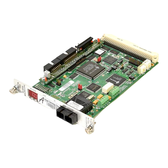
MACRO CPU Board Hardware Reference Manual INTRODUCTION The 3U MACRO-CPU board is the processor and MACRO interface board that is used in a 3U MACRO Station (in either UMAC MACRO or MACRO Stack configuration). Note: Three documents describe the operation of Delta Tau Data Systems Inc. 3U MACRO Station products: •... -
Page 7: Product Configurations (General Description)
MACRO CPU board, or a 3U Turbo PMAC2 CPU board. Most other 3U-format boards, labeled Accessory boards, can be used with either CPU board. • When the 3U MACRO-CPU board is used, the resulting assemblies are called UMAC MACRO or 3U MACRO Stack. •... -
Page 8: Macro Cpu Specifications
MACRO CPU Board Hardware Reference Manual MACRO CPU Specifications Physical Specifications Size: 16cm x 10cm x 3.6cm (6.3" x 3.95" x 1.4") Weight: ½ lb. Temperature Operating: 0°C to 60°C (32°F to 140°F) Storage: 12°C to 82°C (10°F to 180°F) Humidity: 10% to 95%, non condensing Electrical Specifications... - Page 9 MACRO CPU Board Hardware Reference Manual Introduction Artisan Technology Group - Quality Instrumentation ... Guaranteed | (888) 88-SOURCE | www.artisantg.com...
-
Page 10: Configuration And Hardware Setup
Note: It is recommended that only the new MACRO CPU boards, which have stronger backplane bus drivers, be used in UMAC pack configurations. The 3U MACRO-CPU can be purchased in two physical configurations, distinguished by part number prefix: • 300-602804-10x provides the 3U MACRO-CPU board without a front plate. This configuration is recommended for stack assemblies. -
Page 11: Board Jumper And Switch Setup
MACRO CPU Board Hardware Reference Manual Board Jumper and Switch Setup The MACRO Station has two 16-way rotary switches on the MACRO CPU board that establish the station’s basic configuration on the MACRO ring. SW1 Rotary Switch Setting: SW1 establishes how many servo nodes, and which servo nodes, will be used on the MACRO station. -
Page 12: Board Connections
MACRO CPU Board Hardware Reference Manual Power Supply Check Jumper: Remove jumper E4 if you are not bringing a +/-12V to +/-15V supply into the Compact MACRO Station itself (5V only). If bringing these analog circuit supplies into the Compact MACRO Station, it is best to have jumper E4 on, so that the servo outputs are disabled if either of the analog supplies is lost. - Page 13 MACRO CPU Board Hardware Reference Manual Configuration and Hardware Setup Artisan Technology Group - Quality Instrumentation ... Guaranteed | (888) 88-SOURCE | www.artisantg.com...
-
Page 14: Jumper And Switch Configurations
MACRO CPU Board Hardware Reference Manual JUMPER AND SWITCH CONFIGURATIONS Card Layout The Location columns of the following tables refer to the mapped locations shown in the drawings below: Note: Pin 1 of an E-point is masked by an X in white ink on the composite side and by a square solder pad on the solder side. -
Page 15: E1: Watchdog Timer Disable
MACRO CPU Board Hardware Reference Manual E1: Watchdog Timer Disable Rev –105 and Rev –104 and Jumper Description Default Later Location Earlier Location Type 2-Pin Remove jumper to enable Watchdog Timer. Not jumpered Jump pins 1 and 2 to disable Watchdog Timer (for test purposes only). -
Page 16: E40: Macro Input (Fiber/Wired) Selector
MACRO CPU Board Hardware Reference Manual E40: MACRO Input (Fiber/Wired) Selector Rev –105 and Rev –104 and Jumper Description Default Later Location Earlier Location Type 2-Pin Remove jumper to select MACRO wired Jumpered (RJ45) input from J14. (Option A) Jump pins 1 and 2 to select MACRO fiber Not jumpered optic input from U73. -
Page 17: Switch Configurations
MACRO CPU Board Hardware Reference Manual Switch Configurations SW1: MACRO Slave Node Configure SW1 Setting # of Servo Channels MACRO Servo Station Station Channel and Nodes Used Nodes Specified Channel Nos. Starting Addresses 0 (default) 0, 1, 4, 5 1, 2, 3, 4 $C000, $C008, $C010, $C018* 8, 9, 12, 13 1, 2, 3, 4... -
Page 18: Sw2: Macro Master Number Select
MACRO CPU Board Hardware Reference Manual SW2: MACRO Master Number Select 0: Commanded from Master IC # 0 1: Commanded from Master IC # 1 … F: Commanded from Master IC # F (15) Connector Summary JEXP_A: for interboard connection JEXP_B: for interboard connection JEXP_C: for interboard connection JISP: Factory configuration header... - Page 19 MACRO CPU Board Hardware Reference Manual Jumper and Switch Configurations Artisan Technology Group - Quality Instrumentation ... Guaranteed | (888) 88-SOURCE | www.artisantg.com...
-
Page 20: Macro Station Character Display
MACRO CPU Board Hardware Reference Manual MACRO STATION CHARACTER DISPLAY The Compact MACRO Station has a single hexadecimal character display on the CPU/Interface Board that provides useful information as to the status of the station. The display can show the following values: Value Meaning... - Page 21 MACRO CPU Board Hardware Reference Manual MACRO Station Character Display Artisan Technology Group - Quality Instrumentation ... Guaranteed | (888) 88-SOURCE | www.artisantg.com...
-
Page 22: Firmware Updates
MACRO CPU Board Hardware Reference Manual FIRMWARE UPDATES Downloading new firmware to the MACRO Station is a simple process once the MACRO board is setup properly. To download new firmware to the MACRO station, the user must have the following items: •... - Page 23 MACRO CPU Board Hardware Reference Manual Firmware Updates Artisan Technology Group - Quality Instrumentation ... Guaranteed | (888) 88-SOURCE | www.artisantg.com...
-
Page 24: Board Connector Pinouts
MACRO CPU Board Hardware Reference Manual CONNECTOR PINOUTS The schematic circuits shown in this section are for interface reference only. Subtle differences may exist between the circuits shown here and the actual hardware used. J6: (JTHW) Multiplexer Port Connector (26-pin head at Location D-3) Front View Pin # Symbol... -
Page 25: J7: (Jrs232) Serial Port Connector
MACRO CPU Board Hardware Reference Manual Circuitry for J6- JTHW Interface J7: (JRS232) Serial Port Connector (10-pin Header at Location C-1) Front View Pin # Symbol Function Description Notes N.C. No connection Bidirect Data Terminal Ready Just tied to DSR TXD/ Output Send Data... -
Page 26: J14, J17: Macro Copper I/O (Opt C)
MACRO CPU Board Hardware Reference Manual Circuitry for J7- JRS232 Interface J14, J17: MACRO Copper I/O (Opt C) (8 pin RJ45) Front View Pin # Symbol Function Description Notes DATA+ Data + Differential MACRO Signal. J17: DATA+ input. J14: DATA+ output. DATA- Data - Differential MACRO Signal... -
Page 27: P1: Ubus Interface Connector
MACRO CPU Board Hardware Reference Manual P1: UBUS Interface Connector (96 pin EURO-Connector at F-1, 2, 3, 4) Front View on MACRO-CPU Card Pin # Row A Row B Row C +5Vdc +5Vdc +5Vdc BD01 DAT0 BD00 BD03 SEL0 BD02 BD05 DAT1 BD04... -
Page 28: U73: Macro Fiber Optic Connector (Option A)
MACRO CPU Board Hardware Reference Manual U73: MACRO Fiber Optic Connector (Option A) (2 Socket SC-Style) Front View Pin # Symbol Function Description Notes Fiber Input MACRO Ring Receiver Fiber Output MACRO Ring Transmitter A. The fiber optic version of MACRO uses 62.5/125 multi-mode glass fiber optic cable terminated in an SC-style connector. - Page 29 MACRO CPU Board Hardware Reference Manual Connector Pinouts Artisan Technology Group - Quality Instrumentation ... Guaranteed | (888) 88-SOURCE | www.artisantg.com...
-
Page 30: Hardware Memory Map
MEMCS1- $E000 UBUS hardware I/O field (was VMECS-) The addressing field size is 16-bits in the 3U MACRO-CPU. The address table above is similar to the PMAC2 product line. Hardware Memory Map Artisan Technology Group - Quality Instrumentation ... Guaranteed | (888) 88-SOURCE | www.artisantg.com... - Page 31 MACRO CPU Board Hardware Reference Manual Hardware Memory Map Artisan Technology Group - Quality Instrumentation ... Guaranteed | (888) 88-SOURCE | www.artisantg.com...
-
Page 32: Accessories
MACRO CPU Board Hardware Reference Manual ACCESSORIES Both the Turbo and the MACRO CPU boards can support either the Stack or the UMAC configuration. The systems are configured modularly with the selection of a series of accessory boards, some appropriate for the Stack, and some appropriate for the UMAC. - Page 33 MACRO CPU Board Hardware Reference Manual 4-Axis Analog ± 10V Input 4-Axis Analog ± 10V Input 4-Axis Analog ± 10V Input Amplifiers – Analog Linear Amplifier, 24VDC, PWM Amplifier, 48VDC, PWM Amplifier, 70VDC, ±10VDC Input (Brush 0.5/1A, 300-603489-10x 2/4A, 300-603443-10x 8/12A, 300-603486-10x Motors) Backplane, Double Analog...
Need help?
Do you have a question about the 3U MACRO-CPU and is the answer not in the manual?
Questions and answers