Table of Contents
Advertisement
Quick Links
Advertisement
Table of Contents

Related Manuals for Delta Tau MACRO CPU BOARD 4Ax-602804-xHxx


Summary of Contents for Delta Tau MACRO CPU BOARD 4Ax-602804-xHxx
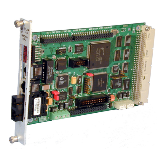
- Page 1 HARDWARE REFERENCE MANUAL MACRO CPU BOARD HRM for UMAC MACRO & MACRO Stack 4Ax-602804-xHxx January 29, 2003 Single Source Machine Control Power // Flexibility // Ease of Use 21314 Lassen Street Chatsworth, CA 91311 // Tel. (818) 998-2095 Fax. (818) 998-7807 // www.deltatau.com...
-
Page 3: Table Of Contents
MACRO-CPU Hardware Reference CONTENTS INTRODUCTION ........................1 3U Product Configurations (General Description) .........................2 MACRO CPU Specifications ..............................4 Physical Specifications................................4 Electrical Specifications ................................4 3U MACRO-CPU CONFIGURATION..................5 3U MACRO CPU BOARD HARDWARE SETUP..............7 3U MACRO CPU Board Jumper & Switch Setup .........................7 MACRO CPU Board Connections ............................8 3U MACRO-CPU JUMPER AND SWITCH CONFIGURATIONS ........... - Page 4 MACRO-CPU Hardware Reference U MACRO-CPU HARDWARE MEMORY MAP ..............28 ACCESSORIES ........................30 Contents...
-
Page 5: Introduction
3U MACRO CPU. The UMAC MACRO and the MACRO Stack provide a remote interface for encoders, flags, direct-PWM digital drives, analog drives, stepper drives, analog I/O, and digital I/O for Delta Tau Data's PMAC products that have a MACRO interface. -
Page 6: Product Configurations (General Description)
MACRO-CPU Hardware Reference 3U MACRO-CPU Board (3A0-602804-10x): • 80MHz DSP56303 CPU • 512k x 8 flash memory for user backup & firmware • Latest released firmware version • RS-232 serial interface for setup and debugging • Stack connectors for servo and I/O accessory boards •... - Page 7 MACRO-CPU Hardware Reference Assemblies of 3U-format boards can be made with either of two CPU processor boards – a 3U MACRO-CPU board, or a 3U Turbo PMAC2 CPU board. Most other 3U-format boards, labeled “Accessory” boards, can be used with either CPU board. •...
-
Page 8: Macro Cpu Specifications
MACRO-CPU Hardware Reference MACRO CPU Specifications Physical Specifications Size: 33.5cm x 9.9cm x 3.8cm (13.2" x 3.9" x 1.4") Weight: ½ lb. Temperature Operating: 0°C to 60°C (32°)F to 140°F) Storage: 12°C to 82°C (10°F to 180°F) Humidity: 10% to 95%, noncondensing Electrical Specifications Power: 1.5A @ +5V (±5%) (7.5W) Pertains to 8-channel configuration, with a typical load of... -
Page 9: Macro-Cpu Configuration
MACRO-CPU Hardware Reference 3U MACRO-CPU CONFIGURATION The purchase of the 3U MACRO CPU board provides a 3U-format (100mm x 160mm) board with a DSP processor, MACRO ring circuitry, “piggyback” connectors onto which “stack” accessory boards can be mounted, and a backplane connector through which other 3U-format boards can be connected by means of a “UBUS” passive-backplane board. - Page 10 MACRO-CPU Hardware Reference 3U MACRO-CPU Configuration...
-
Page 11: Macro Cpu Board Hardware Setup
MACRO-CPU Hardware Reference 3U MACRO CPU BOARD HARDWARE SETUP The hardware setup of the 3U MACRO CPU Board consists of the setting of 2 rotary switches, the setting of several E-point jumpers on each board, followed by power supply and signal connections. Note E-Point Jumper numbers are shown in white ink on the legend of each board. -
Page 12: Macro Cpu Board Connections
MACRO-CPU Hardware Reference SW2 Rotary Switch Setting: SW2 establishes the number of the master IC to which the MACRO station will respond. The values of 0 to 15 correspond to Master numbers 0 to 15, respectively. For a non-Turbo PMAC2 master, this value must match the master number value in the first hexadecimal digit of PMAC2’s I996. - Page 13 MACRO-CPU Hardware Reference ACC-Ux “UBUS” backplane board. It can also be used to bring in 5V power, and optionally +/-15V power, from a backplane or breakout board, to the entire MACRO Station. Note When interfacing to accessory boards across the UBUS backplane, it is strongly recommended to use a new revision (-105 or higher) of the MACRO CPU board, and an ACC-Ux backplane board (not an older ACC-Jx backplane board).
- Page 14 MACRO-CPU Hardware Reference 3U MACRO CPU Board Hardware Setup...
-
Page 15: Macro-Cpu Jumper And Switch Configurations
MACRO-CPU Hardware Reference 3U MACRO-CPU JUMPER AND SWITCH CONFIGURATIONS 3U MACRO-CPU Card Layout The "Location" columns of the follow table s refe r to t he ma pped locati ons s hown in the drawings below: A B C D E F REV-105 and Later Revisions REV-104 and Earlier Revisions Note:... -
Page 16: E1: Watchdog Timer Disable
MACRO-CPU Hardware Reference E1: Watchdog Timer Disable Rev -105 Rev -104 Jumper Description Default and Later and Earlier Type Location Location Remove jumper to enable Watchdog Timer. not jumpered 2-PIN Jump pins 1 and 2 to disable Watchdog Timer (for test purposes only) E2: CPU Mode Operation Rev -105... -
Page 17: E40: Macro Input (Fiber/Wired) Selector
MACRO-CPU Hardware Reference E5: MACRO Received Signal Detect/Bypass Mode (rev -105 and 106 only). Does not exist on rev 107 and later models. Rev -105 Rev -104 Jumper Description Default and Later and Earlier Type Location Location Jump pins 1 and 2 to access the receiver’s signal detect operation. Pin 1-2 Jump pins 2 and 3 to bypass the receiver’s signal detect operation. -
Page 18: Jp5-Jp6: Macro Copper Eq Select (Rev -104 And Earlier)
MACRO-CPU Hardware Reference JP5-JP6: MACRO Copper EQ Select (rev -104 and earlier) Rev -105 Rev -104 Jumper Description Default and Later and Earlier Type Location Location These jumpers are used to select different modes of not jumpered equalization when copper-based communications are used. When not jumpered, adaptive equalization is used. -
Page 19: Switch Configurations
MACRO-CPU Hardware Reference Switch Configurations SW1: MACRO Slave Node Configure # of Servo MACRO Station Station Axis Axis PMAC2's I996 PMAC2's I1000, Setting Channels Servo Channel Channel Board Board Value ** I1002 Value & Nodes Nodes Nos. Starting Servo Servo (Turbo (Turbo Used... -
Page 20: Connector Summary
MACRO-CPU Hardware Reference Connector Summary ☼ JEXP_A: for interboard connection ☼ JEXP_B: for interboard connection ☼ JEXP_C: for interboard connection ☼ JISP: Factory configuration header ☼ JTAG/OnCE: Factory troubleshoot header JTHW: Multiplexer Port Connector JRS232: Serial Port Connector J14, J17: RJ45: MACRO Copper I/O (OPT C) JEXP: Backplane Expansion Port Connector TB1:... -
Page 21: Macro Station Character Display
MACRO-CPU Hardware Reference MACRO STATION CHARACTER DISPLAY The Compact MACRO Station has a single hexadecimal character display on the CPU/Interface Board that provides useful information as to the status of the station. The display can show the following values: Value Meaning (Blank) Ring not active... -
Page 22: Hardware Re-Initialization
MACRO-CPU Hardware Reference HARDWARE RE-INITIALIZATION MACRO hardware reinitialization to factory defaults is enabled when the SW1 setting is set to 15 or F (hexidecimal) and the power is cycled at the MACRO Station. The only time the user would want to use a hardware reinitialization to factory defaults with the MACRO Station would be if the MACRO Station always powers up with a watchdog (typically if the ring clock at the Ultralite is different than the ring clock at the MACRO Station). - Page 23 MACRO-CPU Hardware Reference Hardware Re-initialization...
-
Page 24: Firmware Updates
MACRO-CPU Hardware Reference FIRMWARE UPDATES Downloading new firmware to the MACRO Station is a simple process once the MACRO board is setup properly. To download new firmware to the MACRO station, the user must have the following items: 5V power supply 2 jumpers DB9 female to 10 pin header (any cable used for PMAC RS232 communications) PC at the DOS prompt. - Page 25 MACRO-CPU Hardware Reference Firmware Updates...
-
Page 26: Macro-Cpu Board Connector Pin-Outs
MACRO-CPU Hardware Reference 3U MACRO-CPU BOARD CONNECTOR PIN-OUTS The schematic circuits shown in this section are for interface reference only. Subtle differences may exist between the circuits shown here and the actual hardware used. J6: (JTHW) Multiplexer Port Connector (26-pin Header at Location D-3) Front View Pin # Symbol... - Page 27 MACRO-CPU Hardware Reference VDD2 IO_00 FLAG_W1 FAULT_1 DATA_2 IO_01 FLAG_V1 FAULT_2 DATA_3 IO_02 FLAG_U1 EQU_1 DATA_4 IO_03 FLAG_T1 EQU_2 DATA_5 IO_04 FLAG_D1 AENA_1 DATA_6 IO_05 FLAG_C1 AENA_2 DATA_7 IO_06 FLAG_B1 IO_07 FLAG_A1 DATA_0 ENC_C1 ENC_B1 ENC_A1 PUL_1 PWM_C_B1 DIR_1 PWM_C_T1 IO_08 PWM_B_B1 IO_09 PWM_B_T1 IO_10 PWM_A_B1...
-
Page 28: J7: (Jrs232) Serial Port Connector
MACRO-CPU Hardware Reference J7: (JRS232) Serial Port Connector (10-pin Header at Location C-1) Front View Pin # Symbol Function Description Notes N.C. No connection BIDIRECT Data Terminal Ready Just tied to “DSR” TXD/ OUTPUT Send Data Transmit data to host INPUT Clear to Send Host Ready bit... -
Page 29: J14, J17: Macro Copper I/O (Opt C)
MACRO-CPU Hardware Reference J14, J17: MACRO COPPER I/O (OPT C) (8 pin RJ45) Front View Pin # Symbol Function Description Notes DATA+ Data + Differential MACRO Signal. J17: DATA+ input. J14: DATA+ output. DATA- Data - Differential MACRO Signal J17: DATA- input. J14: DATA- output. -
Page 30: P1: Ubus Interface Connector
MACRO-CPU Hardware Reference P1: UBUS Interface Connector (96 pin EURO-Connector at F-1, 2, 3, 4) Front View on MACRO-CPU Card Pin # Row A Row B Row C +5Vdc +5Vdc +5Vdc BD01 DAT0 BD00 BD03 SEL0 BD02 BD05 DAT1 BD04 BD07 SEL1 BD06... -
Page 31: Tb1: (Jpwr) 4-Pin Terminal Block
MACRO-CPU Hardware Reference TB1: (JPWR) 4-Pin Terminal Block (Location B-4) Pin # Symbol Function Description Notes Common Reference Voltage Input Positive Supply Voltage Supplies all PMAC digital circuits +15V Input Positive Supply Voltage +12V to +15V; used for on-board analog -15V Input Negative Supply Voltage... -
Page 32: U Macro-Cpu Hardware Memory Map
MACRO-CPU Hardware Reference U MACRO-CPU HARDWARE MEMORY MAP The values in this table represent the hardware locations associated with register-based transactions that occur in the 3U MACRO-CPU. Reference ADDR (hex) Description CS00- $FFC0 Stack I/O select #1 CS02- $FFC8 Stack I/O select #2 CS04- $FFD0 Stack I/O select #3... - Page 33 MACRO-CPU Hardware Reference U MACRO-CPU Hardware Memory Map...
-
Page 34: Accessories
MACRO-CPU Hardware Reference ACCESSORIES Both the Turbo and the MACRO CPU boards can support either the Stack or the UMAC configuration. The systems are configured modularly with the selection of a series of accessory boards, some appropriate for the Stack, and some appropriate for the UMAC. These accessories are listed here. Each has its own manual for detailed description. -
Page 35: Power Supplies
MACRO-CPU Hardware Reference Boards Backplane, 300-603462 Backplane, Backplane, 300-603403-10x 300-603463-10x ACC-U10, UBUS 10-Slot ACC-U12, UBUS 12-Slot ACC-U14, UBUS 14-Slot Backplane, Backplane, Backplane, 300-603464-10x 300-603465-10x 300-603466-10x ACC-U16, UBUS 16-Slot ACC-U18, UBUS 18-Slot Backplane, Backplane, 300-603471-10x 300-603491-10x 4-Axis Analog ± 10V Input 4-Axis Analog ±...
Need help?
Do you have a question about the MACRO CPU BOARD 4Ax-602804-xHxx and is the answer not in the manual?
Questions and answers