Table of Contents
Advertisement
Quick Links
Advertisement
Table of Contents
Troubleshooting

Related Manuals for IFM Electronic LDP100


Summary of Contents for IFM Electronic LDP100
- Page 1 Operating instructions Optical particle monitor LDP100...
-
Page 2: Table Of Contents
LDP100 Optical particle monitor Contents Preliminary note ............. - Page 3 Optical particle monitor LDP100 9.9.4.1 Decoding of error bits ......... . . 25 9.9.5...
-
Page 4: Preliminary Note
LDP100 Optical particle monitor 1 Preliminary note You will find instructions, technical data, approvals and further information using the QR code on the unit / packaging or at documentation.ifm.com. 1.1 Symbols used Requirement Instructions Reaction, result [...] Designation of keys, buttons or indications... -
Page 5: Safety Instructions
Optical particle monitor LDP100 2 Safety instructions • The unit described is a subcomponent for integration into a system. – The system architect is responsible for the safety of the system. – The system architect undertakes to perform a risk assessment and to create documentation in accordance with legal and normative requirements to be provided to the operator and user of the system. -
Page 6: Intended Use
LDP100 Optical particle monitor 3 Intended use This product is a hydraulic component. This device is an optical particle monitor used to monitor the purity of hydraulic oils. It uses the principle of light extinction (attenuation of radiation) and measures particles in the fluid. -
Page 7: Function
Optical particle monitor LDP100 4 Function 4.1 Measuring principle The device operates on the light-extinction principle. The particles are classified in a measuring cell with regard to their size and number using a laser. The measured value is provided according to ISO 4406:21 (factory setting) or SAE AS4059F or NAS 1638. -
Page 8: Installation
Take the appropriate care when performing work on the back of the device. The sensor is supplied without installation / connection accessories. Only use accessories from ifm electronic gmbh! The optimum function is not ensured when using components from other manufacturers. -
Page 9: Installation
Optical particle monitor LDP100 M5x5,5 Fig. 2: View of the back Pressure compensation diaphragm 5.2 Installation Connect the particle monitor to a bypass pressure line. Any direction of flow is permitted. The device should be installed in an accessible location to be able to read the display and use the keypad. -
Page 10: Mechanical Load
LDP100 Optical particle monitor Rule for the length of lines: The shorter, the better. With increasing length there is a higher risk that larger particles settle. Particularly when using Minimess lines, the pressure should be sufficiently high to guarantee the required flow volume (Ò Volume flow and viscosity). -
Page 11: Volume Flow And Viscosity
Optical particle monitor LDP100 Fig. 4: Acceptable pressure characteristics Fig. 5: Unacceptable pressure characteristics 5.5 Volume flow and viscosity To ensure reliable operation, the device requires a constant volume flow between 50 and 400 ml/min. This value applies to both directions of flow; the direction can be freely selected. -
Page 12: Absence Of Bubbles And Water Droplets
LDP100 Optical particle monitor 410 mm²/s 197 mm²/s 55 mm²/s Fig. 6: Volume flow and viscosity Δp in bar Volume flow in l/min Acceptable range You can estimate the required pressure difference (Δp) for a flow volume using the diagram above. -
Page 13: Electrical Connection
Optical particle monitor LDP100 6 Electrical connection The unit must be connected by a qualified electrician. Observe the national and international regulations for the installation of electrical equipment. Voltage supply according to SELV, PELV. Use a screened sensor cable! u Disconnect power. -
Page 14: Operating And Display Elements
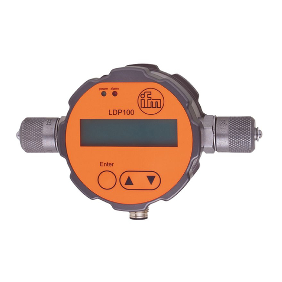
LDP100 Optical particle monitor 7 Operating and display elements 1: LED green [power] 2: LED red [alarm] 3: Display 4: Selection button [Enter] 5: “Up” [▲] / “down” [▼] button 4: Selection button [Enter] By means of the selection button you can jump to the next menu level; if values are to be set, press the selection button to jump to the next position. -
Page 15: Status Display
Optical particle monitor LDP100 7.2 Status display Measurement running [►] flashing continuously: sensor is soiled / oil is too dark. Laser adjusting [►] flashing: at the start of each measurement for approx. 2 to 3 seconds. Device in pause mode [II]. -
Page 16: Menu Structure
LDP100 Optical particle monitor 8 Menu structure Start screen TIME CONTROL DELAY TIME Set time OPERATION MODE DIGITAL I/O Set time SAMPLE TIME BUTTON AUTOMATIC STD. ALARM ALARM TYPE Select cleanliness ALARM SETTINGS FILTER MODE Select cleanliness Select limit TEMPERATURE ALARM MEMORY... - Page 17 Optical particle monitor LDP100 Select type COMMUNICATION TYPE BAUDRATE CAN Set baud rate + resistance NODE-ID CAN Select node ID PDU2 INTERVAL Select interval DISPLAY SETT. LIGHTING Select lighting type Set contrast CONTRAST SENSOR PARAM. MEASUREMENT Display current measurement Display measurement history HARDWARE Display electr.
-
Page 18: Parameter Setting
LDP100 Optical particle monitor 9 Parameter setting 9.1 Operation mode There are four operation modes which can be configured in the menu. At the start of a measurement, the internal laser adjusts automatically. This process can be identified by the [▶] symbol flashing on the screen and usually takes about 2 to 3 seconds. -
Page 19: Button
Optical particle monitor LDP100 9.1.3 Button There are two ways to start or end a measurement. • By manually pressing the [↲] button. • Using a “Start” and “Stop” command via the digital communication line. This can be done via CANopen or CAN J1939. -
Page 20: Filter Mode
LDP100 Optical particle monitor Standard Setting range Value for deactivation Alarm conditions ISO 4406:21 0, 1, 2…28 ON 4 μm ≥ limit value or ON 6 μm ≥ limit value or SAE AS 4059F 000, 00, 0, 1, 2...12 ON 14 μm ≥ limit value or ON 21 μm ≥ limit value NAS 1638... -
Page 21: Low-Pass Filter
9.2.3 Low-pass filter In a hydraulic system, short-term concentration increases (peaks) can occur, which are not representative of the entire system, e.g. by operating a hand valve. The LDP100 detects these changes and displays them correctly. The low-pass filter ensures that if an alarm limit has been set, the alarm will not be triggered at each peak. -
Page 22: Analogue Setting
LDP100 Optical particle monitor 9.3 Analogue setting The measurement results can be output via the analogue current output (4..20 mA). The table below provides an overview of the setting options. For measuring the current and conversions see: Analogue current output (Ò / 29) Menu selection Analogue current output 4 μm... -
Page 23: Type
Optical particle monitor LDP100 9.6.1 Type Here you define the configuration of the digital interface. Only one type can be chosen. The physical connection is always the same. The following types are available: • CANopen • CAN J1939 CAN J1939 is available from device status AB. -
Page 24: Display Settings
LDP100 Optical particle monitor 9.8 Display settings A variety of display setting options are available. • Lighting: Selection whether the background lighting should be permanently active or whether it should be deactivated automatically after 10 seconds. • Contrast: Adjust the contrast via a bar display. -
Page 25: Hardware
Optical particle monitor LDP100 9.9.2 Hardware Shows internal sensor parameters. This cannot be changed by the user. • Laser current: The current which operates the internal laser. The value should be between 1 mA and 2.8 mA. If the value is outside this range, there is a risk of malfunction. - Page 26 LDP100 Optical particle monitor Hexadecimal Binary 0001 0010 0011 0100 0101 0110 0111 1000 1001 1010 1011 1100 1101 1110 1111 The binary code in the table describes the states of the 16 error bits of the device. Below is an error information decoding example.
-
Page 27: Flow Adjust
Optical particle monitor LDP100 Bit no. LSB 0 ERC1 Last calibra- First cali- tion limit bration limit (S5) (S1) reached reached ERC2 ERC3 Measuring Tempera- Tempera- Detector Detector Laser cur- Laser cur- mode = au- ture ture > 80 °C voltage too... -
Page 28: Calibration
LDP100 Optical particle monitor 10 Calibration The measuring device is calibrated in accordance with ISO 11943. The equipment used for the calibration is primary calibrated according to ISO 11171 and is thus traceable to NIST SRM 2806. The sign μm (c) indicates particle size calibration using ISO-MTD test dust. -
Page 29: Analogue Current Output
Optical particle monitor LDP100 11 Analogue current output 11.1 Measurement without load resistance Perform the current measurement with a suitable current measuring device. Pin 6 Pin 8 Fig. 11: Current measurement without load resistance For the calculation of the ordinal numbers for the various standards, see:... -
Page 30: Conversion Of Analogue Current Output To Ordinal Number
LDP100 Optical particle monitor 11.4 Conversion of analogue current output to ordinal number The analogue current output supplies a signal from 4 to 20 mA. The conversions to the respective ordinal numbers are described below. Comparison table current output to ordinal number - ISO and SAE... -
Page 31: Sequential 2
Optical particle monitor LDP100 4 µm 6 µm 14 µm 21 µm start sequence current in mA time in seconds 11.5.2 Sequential 2 If the analogue current output is configured to “SEQUENTIAL 2”, the four ordinal numbers and three error messages are sequentially output via the analogue interface (4...20 mA) using a predefined time pattern. - Page 32 LDP100 Optical particle monitor Bar 1 Bar 2 Bar 3 Below is an example of an entire sequence illustrating how to read the table and current values for the sequences Bar 1-Bar 3. The precondition is a powered, empty device with no flow passing through it.
-
Page 33: Switching Inputs And Switching Outputs
Optical particle monitor LDP100 12 Switching inputs and switching outputs 12.1 Digital input The digital input is required for the Digital I/O measurement mode. To start and stop a measurement, pin 5 must be connected to either L- or L+. For further information see: Ò Digital I/O 12.2 Switching output... - Page 34 LDP100 Optical particle monitor With voltage measure- When consumer con- Alarm Explanation ment nected Present (true) Internal transistor connects pin 7 to pin 2. = L+ Alarm The voltage is measured against L-. = 4 W = 0.5 A Not present (false) Pin 7 is not connected internally (floating) = L- = 0 V...
-
Page 35: Can Communication
Optical particle monitor LDP100 13 CAN communication The CAN interface corresponds to “CAN 2.0B Active Specification”. The sensor supports a limited number of transmission speeds on the CAN bus. Transmission rate Supported CiA Draft 301 Bus length per CiA Draft Standard 301... -
Page 36: Canopen Object Dictionary" In General
LDP100 Optical particle monitor 13.1.1 “CANopen Object Dictionary” in general The CANopen Object Dictionary (OD) is an object dictionary in which each object can be addressed with a 16-bit index. Each object can consist of several data elements which can be addressed via an 8-bit subindex. -
Page 37: Service Data Object (Sdo)
Optical particle monitor LDP100 Com. Object Initializing Pre-Operational Operational Stopped Synch BootUp 13.1.3 Service Data Object (SDO) Service Data Objects enable write and read access to the sensor’s object directory. Each SDO is acknowledged and transmission only takes place between two participants, a so-called client/server model. -
Page 38: Process Data Object (Pdo)
LDP100 Optical particle monitor The example below is an SDO query of the sensor’s serial number from the object dictionary at index 0x1018, subindex 4, with a data length of 32 bits. The client (controller) sends a read request to the sensor with the ID “NodeID”. -
Page 39: Pdo Mapping
Optical particle monitor LDP100 PDOs are ideally suited for transferring data from sensors to the controller or from the controller to actuators. PDO attributes of the sensor at a glance: • The sensor supports three Transmit PDOs (TPDOs), no Receive PDOs (RPDOs). The level sensors support four TPDOs. -
Page 40: Canopen Object Dictionary" In Detail
LDP100 Optical particle monitor Principle of mapping multiple OD objects in a TPDO: TPDO2 Kommunikationsparameter im OD, an Index 0x1801 Betriebszeit- Objekt TPDO2 SAE4µm SAE6µm SAE14µm SAE21µm stempel Highest Subindex Byte in U 32 COB-ID CAN- Transmission Type Msg. n. a. - Page 41 Optical particle monitor LDP100 Mapped SIdx Name Type Attr. Default Notes auf PDO 1800h transmit record PDO1 Param- eter Number of en- unsigned largest sub index tries COB-ID unsigned 180h+N COB-ID used by PDO, (bit 30 must always be odeID range: 181h..1FFh, can...
- Page 42 LDP100 Optical particle monitor Mapped SIdx Name Type Attr. Default Notes auf PDO 1803h event timer unsigned 1F4h event timer in ms for asynchronous TPDO3 range: 0..65535, multi- ple of 10ms 1A00h TPDO1 Map- record ping Parame- Number of en-...
- Page 43 Laser operat- unsigned Operating hours of the ing time in laser hours reserved unsigned Time to next calibra- tion - disabled for LDP100 Time to threshold to S1 2001h ISO measure- record ment Number of en- unsigned largest sub index tries ISO4 µm...
- Page 44 6: C <= ISO 9 Time reached 5 Autoparts not reached 6 Concentration too low reserved unsigned reserved unsigned Calibration hint - disa- bled for LDP100 Bit 0: Threshold S1 reached Bit 1: Threshold S5 reached reserved unsigned reserved unsigned reserved unsigned...
- Page 45 Optical particle monitor LDP100 Mapped SIdx Name Type Attr. Default Notes auf PDO 2003h Measurement unsigned Bit0: Measurement run- Bit 6 and 7: corre- info ning sponds to the alarm LED being switched Bit1: Measurement on and the open col- mode: Time controlled...
- Page 46 LDP100 Optical particle monitor Mapped SIdx Name Type Attr. Default Notes auf PDO 2030h operation unsigned 0 = time Control mode 1 = digital I/O 2 = button 3 = automatic History disable unsigned 0 = history enabled 1 = history disabled...
-
Page 47: Can J1939
Optical particle monitor LDP100 Mapped SIdx Name Type Attr. Default Notes auf PDO 2032h unsigned alarm threshold NAS Own storage location, offset using the same method as for reading out the data (0 = NAS 00; 1 = NAS 0; etc.) 2100h readmem record control func-... -
Page 48: Pdu Format 1
LDP100 Optical particle monitor Parameter Group Number (PGN) Ext. data page 25 Data page 24 PDU format (PF) Target Adr / Group 23..16 Extension (PS) 15…8 PDU format 1 (specific) 00h – Efh Destination Address (DA) 23…16 15..8 PDU format (global) F0h –... - Page 49 Optical particle monitor LDP100 SPN length (Bit) Name Description Units 0xFF01 520198 SAE 6 µm Ordinal numeral SAE-class 6 µm Ordinal numeral 0 = SAE 000 1 = SAE 00 2 = SAE 0 3 = SAE 1 4 = SAE 2...
- Page 50 LDP100 Optical particle monitor SPN length (Bit) Name Description Units 0xFF03 520206 Sensor status bits Bit 0: Laser current high (I > 2,8 mA) Bit 1: Laser current low (I <1 mA) Bit 2: Photodiode voltage high (U > 4 V) Bit 3: Photodiode voltage low (U < 4 V) Bit 4: Temperature high (T > 80 °C) Bit 5: Temperature low (T < -20 °C)
-
Page 51: Pdu 1 (Addressed)
Optical particle monitor LDP100 13.2.4.2 PDU 1 (addressed) Device Parameter address (Node ID): Type Direc Prio 29Bit ID (hex) Byte 0 Byte 1 Byte 2 Byte 3 Byte 4 Byte 5 Byte 6 Byte 7 tion PDU1 0xEF20 0x1CEF2000 Start and stop measurement (if in... - Page 52 LDP100 Optical particle monitor Device Parameter address (Node ID): Type Direc Prio 29Bit ID (hex) Byte 0 Byte 1 Byte 2 Byte 3 Byte 4 Byte 5 Byte 6 Byte 7 tion PDU1 0xEF20 0x1CEF2000 Flow in deciliter/minute: if 0 is set, the device calculates the...
-
Page 53: Pdu 2 (Broadcast)
Optical particle monitor LDP100 13.2.4.3 PDU 2 (Broadcast) Device address (Node ID): 29Bit ID Byte Type Direction Priority R DP Byte 0 Byte 1 Byte 2 Byte 4 Byte 5 Byte 6 Byte 7 (hex) Internal time stamp of the PDU2 32 0xFF00 0x1CFF0020 ISO 4µm... -
Page 54: Operation
LDP100 Optical particle monitor 14 Operation After power-on the device is in the operating mode. It carries out the measurement and evaluation functions and generates output signals according to the set parameters. LED operation indicators: Operating status LED green (power) LED red (alarm) -
Page 55: Classification Systems
Optical particle monitor LDP100 15 Classification systems The automatic particle counter (APC) used to calibrate the device is primary calibrated according to ISO 11171. The ordinal numbers of the device are displayed according to ISO 4406. They are determined from the detected particle concentrations for 4, 6, 14 and 21 µm(c). -
Page 56: Cleanliness Classes According To Sae As 4059F
LDP100 Optical particle monitor Concentration in particles / ml ISO 4406:21 Display LDP1xx From Up to and including 2,500,000.00 > 28 1,300,000.00 2,500,000.00 640,000.00 1,300,000.00 320,000.00 640,000.00 160,000.00 320,000.00 80,000.00 160,000.00 40,000.00 80,000.00 20,000.00 40,000.00 10,000.00 20,000.00 5,000.00 10,000.00 2,500.00 5,000.00 1,300.00 2,500.00... -
Page 57: Cleanliness Classes According To Nas 1638
Optical particle monitor LDP100 Concentration in particles / ml (ISO MTD) SAE AS 4059F Display LDP1xx 4 μm (A) > 6 μm (B) > 14 μm (C) > 21 μm (D) 250.00 97.30 17.30 3.06 500.00 195.00 34.60 6.12 1,000.00 389.00 69.20... - Page 58 LDP100 Optical particle monitor Comparison of ISO 4406 and NAS 1638 (approximate): - / 12 / 9 - / 17 / 14 - / 13 / 10 - / 18 / 15 - / 14 / 11 - / 19 / 16...
-
Page 59: Maintenance / Repair
Optical particle monitor LDP100 16 Maintenance / repair ATTENTION Ensure utmost cleanliness when working on the hydraulic system. Ingress of dirt and liquids causes malfunctions. The safe function of the device is then no longer guaranteed. Never use solvents or aggressive cleaning agents, as they damage the seals of the device, causing premature ageing. -
Page 60: Faqs
LDP100 Optical particle monitor 17 FAQs Question Answer Why is there a warning triangle in the display? An internal alarm has been triggered. Why is the red LED lit? Compare the settings in the menu under “ALARM SETTINGS”. What is the measuring principle of the particle monitor? The particle monitor uses the principle of light extinction. -
Page 61: Troubleshooting
Optical particle monitor LDP100 18 Troubleshooting Error Possible causes Recommended actions • Unable to communicate via the CAN Cable not correctly connected. First check the correct electrical connec- bus. tion of the sensor, the data cable and the power cable. • Current output < 4 mA Observe the specified wiring. -
Page 62: Transport And Disposal
LDP100 Optical particle monitor 19 Transport and disposal u After use, dispose of the unit in an environmentally friendly way in accordance with the applicable national regulations. u In case of return shipment, ensure that the unit is free from soiling, especially from dangerous and toxic substances.
Need help?
Do you have a question about the LDP100 and is the answer not in the manual?
Questions and answers