Yamaha TF-RACK, TF5/3/1 Manual
- Quick manual (28 pages) ,
- Reference manual (103 pages) ,
- Firmware update manual (12 pages)
Advertisement
Introduction
Intended user
This product was designed for users who are familiar with using analog mixers as part of a PA system.
Intended usage
This product was designed to be installed in a rack mount and used in a variety of locations, such as shops and event spaces, to mix multiple audio sources, such as live band instruments or audio devices used at corporate events.
Included items
- Power cord
- Quick Guide (this document)
- Rubber feet (×4)
- Nuendo Live (DAW software)
Documentation
Quick Guide (this document)
This document primarily explains panel controls, functions, and basic operation of the product.
Using the Reference Manual
The Reference Manual is an electronic file in PDF format. You can read this document on a computer. Use Adobe® Acrobat Reader DC® to read this book on screen, search for words very quickly, print specific pages, or click links to display sections of special interest. The ability to search for words, or to follow links directly to relevant sections in the document, are helpful attributes of this electronic file format. We encourage you to take advantage of these benefits. You can download the latest Adobe Acrobat Reader DC application from the website listed below.
Information about software and firmware
Software
Your TF-series mixer can be used with a variety of utility software.
- TF Editor
This application enables you to set up and operate the unit from a connected computer. You can also use the application to back up mixer settings or set mixer parameters without connecting the unit. - TF StageMix
This app allows you to use your iPad and a Wi-Fi connection to remote control the unit. - MonitorMix
This app allows you to use your mobile device and a Wi-Fi connection to adjust the TF-series mixer's AUX Send remotely. - Yamaha Steinberg USB Driver (Windows only)
This driver software is required when connecting the mixer to your computer. It supports up to 34 channels of audio input and 34 channels of audio output.
Information about the software described here is available on the Yamaha Pro Audio website.
http://www.yamahaproaudio.com/
Information about downloading, installing and setting up the software described here is available on the website listed above. In addition, refer to the installation guide that is included with each program.
Firmware
The firmware contained in your TF-series mixer can be updated to take advantage of new features, feature improvements, and bug fixes. Details about updating the firmware are available online.
http://www.yamahaproaudio.com/
For information about updating and setting up the mixer, please refer to the firmware update guide available on the website.
Nomenclature used in this document
In this document, switch-type controls on the panel are called "keys."
Controls located on the panel are enclosed in [square brackets] (e.g., the [CUE] key) to distinguish them from virtual buttons and knobs displayed on screen. For certain controls, the name of the section appears before the brackets (e.g., FADER BANK [INPUT] key).
| The model number, serial number, power requirements, etc., may be found on or near the name plate, which is at the top of the unit. You should note this serial number in the space provided below and retain this manual as a permanent record of your purchase to aid identification in the event of theft. Model No. Serial No. |
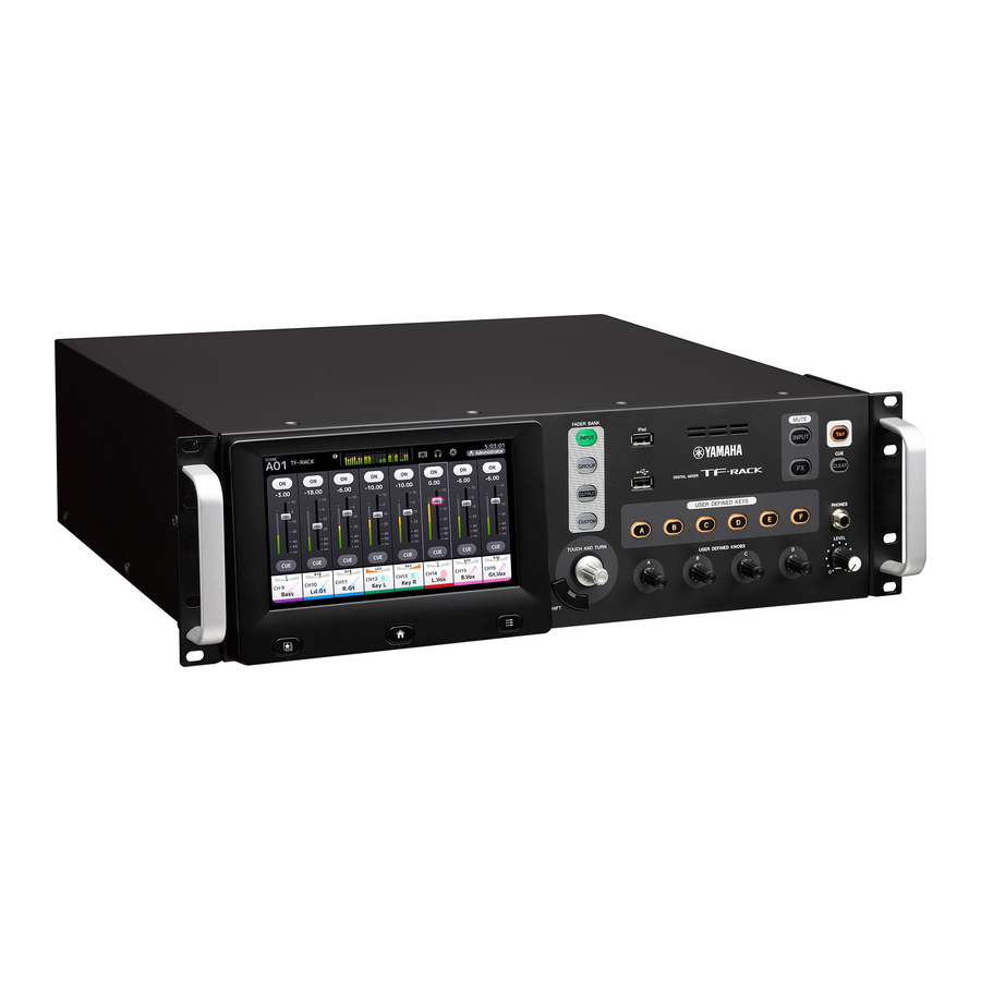
Panels
Front panel

- FADER BANK section
- iPad connector
- USB connector
- MUTE section
- TAP key
- CLEAR CUE key
- USER DEFINED KEYS section
- PHONES section
- USER DEFINED KNOBS section
- Display section
- Ventilation holes
To prevent overheating, do not block the ventilation holes.
Rear panel

- OMNI OUT jacks
Analog signal output jacks. Jacks 1–8 are male XLR3-32 type connectors; jacks 9–16 are TRS phone connectors. These jacks are used to output AUX/ MATRIX channels and STEREO channels. Nominal output level is +4 dBu. You can select which signal is output on the OMNI OUT screen. - ST IN jacks
Stereo input jacks that can be used for connecting a CD player or other line level device. These jacks are unbalanced female RCA jacks. Nominal input level is -10 dBV. - INPUT jacks
Combination jacks that support both XLR and TRS phone connectors. Use these jacks to connect mics and instruments. Nominal input level is -62 dBu to +10 dBu. The head amp setting for each jack is saved in memory. - NETWORK connector
RJ-45 jack used to connect the unit to a computer or smart device via an Ethernet cable (CAT5e or higher recommended). Use STP (Shielded Twisted Pair) cable to prevent electromagnetic interference. - USB TO HOST connector
USB connector used to connect the unit to a computer, allowing the unit to function as an audio interface. Supports input and output for up to 34 channels of up - FOOT SW jack
Used for connecting an optional FC5 foot switch. You can use the connected foot switch as an effect bypass switch, a mute switch, or use it to tap the delay time.
- Expansion slot
Allows you to install an NY card, such as the NY64-D Audio Interface Card. (Installing an NY card) - Exhaust holes
The unit contains a built-in cooling fan. These holes are used to expel air from the unit. To prevent overheating or malfunction, do not block the exhaust holes. ![]() Power switch
Power switch
When the switch is in the![]() position, the power is on. When the switch is in the
position, the power is on. When the switch is in the ![]() position, the power is off.
position, the power is off.- AC IN connector
Connect the included power cord. When connecting to a power outlet, first connect the power cord to the console, then connect the power cord to the power outlet.
 Power switch
  position, the power is on. When the switch is in the
  position, the power is off.
  |
|
Workflow overview
Here's a brief overview of how to start using the TF-RACK.
- Connect
Connect the instruments and mics. Connect output devices such as powered speakers. Connect the included power cord to the AC IN connector.
![]()

When your connections are finished, turn on the power.
NOTICE
- To ensure that the state is saved properly, wait at least 10 seconds after performing the last operation before turning the product off. This product regularly saves the state of its workspace so that it can return to the previous state when the product is turned on.
- After turning the unit off, wait for at least 6 seconds before turning it on again. Rapidly turning the unit off and on in succession can cause it to malfunction.
- Use Presets to Set Up Each Channel
- Select a channel.
![]()
- Press the Library key (
![]() ) to access the Library and recall a Preset.
) to access the Library and recall a Preset.
![]()
- Adjust the channel's parameters. Adjust the input gain, EQ, compressor, and gate. These can be adjusted from the OVERVIEW screen or the individual configuration screens.
> Repeat steps 1 to 3 and set up each channel.
NOTE
You can set up channels without using Presets. For details about the available features and parameters, refer to the Reference Manual.
![]()
- Select a channel.


- Adjust the Mix
Do a sound check and adjust the overall mix.
- Adjusting each channel using the FADER section on the OVERVIEW screen
- Adjusting SEND TO AUX for the level sent to AUX for each channel
- Muting all input channels or effects
- Turning effects on and off, adjusting the overall level of effects "FX1/FX2"
![]()

- Save Your Settings
You can save your entire mix setup as a Scene. Scenes can be recalled later as needed. (SCENE window) You can also save individual channel setups by overwriting existing Presets or by saving them as new Presets in the Library screen.
HINT
Using USER DEFINED KEYS

When the device is in the default state, USER DEFINED KEYS are configured as "Direct Scene Recall" keys. You can save a Scene by pressing and holding down one of the USER DEFINED KEYS, and recall a Scene by pressing one of the USER DEFINED KEYS.
What is a "Preset"?
A Preset is a file stored in the Library ( ) that contains channel settings such as the type of input (instrument or mic), equalizer and compression settings, etc. The default Presets contain settings for various types of instruments, so you can use them as a starting point when setting up a channel. You can edit Presets and save them as new Presets.
What is a "Scene"?
A Scene is a file that contains all the settings for every channel in your mix.

Connections
Connecting outputs

Default signal routing for each output jack
| OMNI OUT 1 | AUX1 OUT |
| OMNI OUT 2: | AUX2 OUT: |
| OMNI OUT 6 | AUX6 OUT |
| OMNI OUT 7 | STEREO L OUT |
| OMNI OUT 8 | STEREO R OUT |
| OMNI OUT 9 | AUX9 OUT |
| OMNI OUT 10: | AUX10 OUT: |
| OMNI OUT 14 | AUX14 OUT |
| OMNI OUT 15 | MONITOR L OUT |
| OMNI OUT 16 | MONITOR R OUT |
Each OMNI OUT jack is configured by default to output a bus. You can change the bus that is output on the SETUP → OMNI OUT PATCH screen. The OMNI OUT jacks can be configured to output the following signals. AUX1–AUX20, MATRIX1–4, STEREO L, STEREO R, SUB, MONITOR L, MONITOR R, NO ASSIGN (no output signal assigned).
Connecting inputs

Default signal routing for each channel
| CHANNEL | TF-RACK |
| CH 1 | INPUT 1 |
| : CH 16 | : INPUT 16 |
| CH 17: | INPUT 1: |
| CH 32 | INPUT 16 |
| ST IN 1L | PLAYBACK L |
| ST IN 1R | PLAYBACK R |
| ST IN 2L | ST IN L |
| ST IN 2R | ST IN R |
Default signal routing for each channel is shown above. To change the signal routing, use the INPUT screen.
HINT
What if I'm using condenser mics?
Phantom power must be supplied to condenser mics. Some direct boxes also need phantom power. When using phantom power, first set "+48V Master" on the SETUP screen to on, then turn phantom power on or off for each channel on the corresponding channel's INPUT screen. Make sure you turn phantom power off if it is not needed. For more details, refer to the Reference Manual.
Why can't I hear anything?
- Is the fader that corresponds to the desired INPUT jack raised?
- Does the input select for each channel match each INPUT jack?
- Is the channel's head amp gain set too low?
- Is the channel's mute turned on?
- Is the channel muted?
Controls and functions
This section briefly introduces the console's features.
NOTE
For details about the available features and parameters, refer to the Reference Manual.
FADER BANK section
Allows you to change the fader bank displayed in the OVERVIEW screen.
The keys light to indicate which fader bank is currently selected.

- [INPUT] key
Displays input channels. - [GROUP] key
Displays group channels. - [OUTPUT] key
Displays output channels. - [CUSTOM] key
Displays the channels assigned to the custom fader bank.
iPad connector
Allows you to connect an iOS device or a USB storage device.

To connect an iOS device, use the dedicated cable that was included with the device. This connector allows you to use audio files on your iOS device as background music.
When a USB storage device is connected, you can use the device to play audio files or record the mixer's output directly and save it as an audio file (format: WAV).
NOTE
When using a USB storage device for recording, use a hard disk drive or other high-speed device. (USB memory drives are not guaranteed to function properly.)
For information about compatible iOS devices, visit the Yamaha pro audio website. http://www.yamahaproaudio.com/
USB connector
Used for connecting USB memory drives.

You can connect a USB memory drive and read/write data from/to the drive.
Supported formats for USB memory drives
Drives formatted using FAT32 are supported.
„„Preventing accidental erasure
Some USB memory drives offer a write-protect feature which prevents accidental data erasure. If you save important data on a USB memory drive, we recommend using the drive's write-protect feature to protect your data from being erased. Conversely, make sure the drive's write-protect feature is turned off before trying to save data to the drive.
NOTE
The ACCESS indicator is displayed in the upper right of the screen while data is being accessed (read, written, erased, etc.). While this indicator is displayed, do not turn off the unit or disconnect the USB memory drive. The unit, the drive, and data stored on the drive could become damaged.
MUTE section
Used to mute all channels in a mute group.

- [INPUT] key
Allows you to mute all channels at once. The key lights when the mute group is muted. - [FX] key
Allows you to mute the FX module. Insertion effects for channels in AUX9/10–AUX19/20 are bypassed. The key lights when the mute group is muted.
HINT
You can remove certain input and FX channels from the mute group by turning MUTE SAFE on for the desired channels.
TAP key

Allows you to tap and set the delay time or modulation speed used for effects on FX1/FX2 and AUX9/10– AUX19/20.
The key flashes in time with the tempo. The tempo you tap on the [TAP] key is applied to effects that have "Sync" set to "On".
You can set the [TAP] key flashing to "Off" in the SETUP screen.
[CLEAR CUE] key

Turns off the CUE for all channels.
The key lights when the CUE is turned on.
USER DEFINED KEYS section

These keys can be customized to control the desired function.
Various functions are assigned by default, such as Direct Scene Recall.
You can assign parameters to each knob in the SETUP screen.
PHONES section

- [PHONES] jack
This is the headphones jack used to monitor signals selected for MONITOR or CUE. - [LEVEL] knob
Controls the level of the [PHONES] jack output.
USER DEFINED KNOBS section

These knobs allow you to adjust the parameters that you've assigned to them.
You can assign parameters to each knob in the SETUP screen.
Display section
Allows to you control the console by touching the touchscreen. You can also use the knobs to perform fine adjustments. You can dive further into various features by pressing the keys to display contextual menus.

- Display
You can use familiar touchscreen operations, such as touch, double-touch, sliding, swiping, pinching in, and pinching out. - Library key (
![]() )
)
Displays the Library screen, from which you can recall Presets. - Home key (
![]() )
)
Returns the display to the OVERVIEW screen. The display will change with the content set in Key Function on the PREFERENCE screen by pressing the home key while the OVERVIEW screen is displayed. - Menu key (
![]() )
)
Displays the menu for the current operation. The key lights when a menu is available. - [TOUCH AND TURN] knob
Allows you to control the parameter of the feature selected on the display.
For information about how to control the parameters. - [SHIFT] key
Provides additional functionality, such as allowing you to switch between the F (frequency) and G (gain) parameters of the EQ handle.
 )
)Operating the display
- Changing screens
The screen switches when you touch an on-screen button.
You can touch an area of the screen to select that area, then touch it again to switch to the configuration screen for that area. If an area is displayed in pink when selected, the area contains a parameter that can be controlled with the [TOUCH AND TURN] knob.
To return to the OVERVIEW screen, press the Home key (![]() ).
).
![]()


NOTE
In the SETUP ¦ PREFERENCE screen, select the contents to be displayed in the OVERVIEW screen by using the Key Function ¦ [HOME] key. When multiple items are selected, the display will change with each press of the Home key ( ).
).

- Scrolling
In the OVERVIEW screen, you can slide the screen left and right to view different channels. When a scroll bar is displayed, you can slide the screen up and down to view more content. To scroll quickly, simply use a swiping gesture.
![]()

- Adjusting the Q (steepness) of the EQ
When in manual mode on the EQ screen, select one of the handles and pinch in or out to adjust the Q.
![]()

NOTE
This functionality is not available when multiple parameters can be controlled by one knob (i.e., 1-knob mode). Use the button at the top of the screen to switch to manual mode.
Using the [TOUCH AND TURN] knob to control parameters
As shown below, touch the parameter you want to control ( ) and then turn the [TOUCH AND TURN] knob as desired (
 ). A pink selection area is displayed around the selected parameter. In the OVERVIEW screen, touch an area of the screen to adjust the parameter in that area. In this case, a pink selection area is displayed around the selected area.

HINT
What is "1-knob" mode?
1-knob mode allows you to control multiple EQ or compressor parameters by simply turning the [TOUCH AND TURN] knob. When 1-knob mode is enabled, parameters cannot be adjusted individually. You can turn 1-knob mode on and off from the EQ and compressor screens.
Displaying the configuration screens
You can view the following screens by touching the buttons in the OVERVIEW screen. To return to the OVERVIEW screen, press the Home key (![]() ) below the display.
) below the display.


To return to the OVERVIEW screen, press the Home key (![]() ) below the display.
) below the display.
The OVERVIEW screen can display the CH STRIP section, the FADER section and the SELECTED CHANNEL section. When the OVERVIEW screen is first displayed, the FADER section is displayed.
By default, you can switch between the FADER section and the CH STRIP section by pressing the Home key (![]() ) while the OVERVIEW screen is displayed.
) while the OVERVIEW screen is displayed.
In the example shown here, we will explain how to switch to the different screens from the input channel screen. For details or information about other screens, refer to the Reference Manual.


Setup
This section explains how to set up the TF series console the first time you turn it on.
Setting the internal clock
Set the console's internal clock, including the date, time, and format. The date and time set here is used as a timestamp when saving Scenes.
- Touch the SETUP icon
![]() .
.
The SETUP screen is displayed.
![]()
- Touch the TIME button.
The screen for setting the time is displayed.
![]()
- Slide the desired fields up and down to set the date and time.
- When finished, touch [OK].
- Press the Home key (
![]() )
)
The OVERVIEW screen is displayed.
 .
. 

 )
)NOTE
The following operations are available on the SETUP screen, including the internal clock settings. For details, refer to the Reference Manual.
- Saving and loading the console settings to/from a USB storage device
- PREFERENCE settings
- Settings for [USER DEFINED KEYS], [USER DEFINED KNOBS] and functions assigned to the foot switch
- Custom fader bank settings
- AUX bus signal type
- OMNI OUT settings
- Settings related to controlling the Tio1608-D that is connected to the NY64-D
- Recall Safe target channel settings
- Mute group settings
- Display brightness settings
- Network settings
Initialization (factory reset)
In the event that an internal memory error occurs or you have forgotten your password and cannot operate the console, you can use the following procedure to initialize the console.
NOTE
All information that you have stored in the unit will be erased when you initialize the unit. Note that the following items will not be erased.
- Network settings
- Internal clock settings
- Input/Output Port Trim on the maintenance screen
- Fader/Channel Color calibration on the maintenance screen Use caution when performing this procedure.
- Turn on the console while holding down the Home key (
![]() ).
). - When the maintenance screen appears, press the Initialize All Memories button.
All settings will be restored to the factory defaults.
Removing the handles
You can remove the handles if they are not needed. The procedure is the same for the left and right handle. The right side is shown here.
- Remove the 3 screws that secure the bracket, and remove the bracket.
![]()
- Remove the 2 screws that secure the handle, and remove the handle.
![]()
- Use the 3 screws removed in step 1 to re-attach the bracket.
![]()


NOTE
When re-attaching the bracket, be sure to use the 3 screws that were original used to secure the bracket.
Rack-mounting the unit
Rack-mounting the unit requires 3 U of space.
Precautions when rackmounting
This unit is rated for operation at ambient temperatures ranging from 0 to 40°C. If you install this unit in a poorly ventilated rack along with other devices, the ambient temperature inside the rack may rise, resulting in inefficient performance. Be sure to follow the guidelines below to prevent overheating.
- When mounting this unit in a rack with devices such as power amplifiers that generate a significant amount of heat, leave more than 1 U of space between this unit and other equipment. Also, either leave the open spaces uncovered or install appropriate ventilating panels to minimize the possibility of heat buildup.
- To ensure sufficient airflow, leave the rear of the rack open and position it at least 10 cm from walls or other surfaces.
If the rear of the rack cannot be left open, install a commercially available fan or similar ventilation product to secure sufficient airflow. If you have installed a fan kit, there may be cases in which closing the rear of the rack will produce a greater cooling effect.
Refer to the rack and/or fan unit manual for details.
Installing an NY card
Before installing an NY card in the expansion slot, confirm that the card is compatible with TF-series consoles. For information about compatible cards, visit the Yamaha pro audio website. http://www.yamahaproaudio.com/
- Confirm that the unit is turned off.
![]()
Inserting or removing a card while the unit is turned on may cause electrical shock and damage to the device. - Remove the screws that secure the slot cover, and then remove the cover.
The screws will be used to secure the NY card. The slot cover will not be used while the card is installed; store it in a safe place for later use.
![]()
- Align the sides of the NY card with the guide rails inside the expansion slot, and then insert the NY card.
Make sure you insert the card fully, so that the connection terminal on the NY card is firmly connected to the connection terminal inside the slot.
Make sure the sides of the NY card with the guide rails of the device you are installing it in.
![]()
- Use the screws you removed in step 2 to secure the NY card.
Do not use the console without using the screws to secure the NY card.
Using the console without securing the card may cause damage to the product and malfunctions.


NOTE
When connecting a Tio1608-D, refer to the Tio1608-D Owner's Manual.
Removing the NY card
- Confirm that the unit is turned off.
![]()
Inserting or removing a card while the unit is turned on may cause electrical shock and damage to the device. - Remove the screws that secure the NY card.
- Insert a flat-head screwdriver or similar tool into the notch at the bottom of the NY card, and pull out the card slightly.
![]()
- Hold the NY card by its panel, and slowly pull the card out of the console.
Attach the slot cover (removed when you installed the card) and use the screws to secure it.Do not use the console without attaching the slot cover.
Using the console without attaching the slot cover may cause damage to the product and malfunctions.

TF-RACK Troubleshooting
| Problems and Causes | Solutions |
No sound | |
| The input source (input port) settings for the input channel are incorrect. | Check the input source (input port) settings on the INPUT screen. |
| The corresponding channel is turned off. | Use the FADER section in the OVERVIEW screen or the CH VIEW screen to turn the channel on. |
| The fader level for the corresponding channel is turned down. | Use the FADER section in the OVERVIEW screen or the CH VIEW screen to turn up the fader level. |
| Phantom power is not being supplied (when using a condenser mic). | Set "+48V Master" on the SETUP screen to on, and then turn on phantom power on the corresponding INPUT screen. |
| The mute is on. | Check the MUTE keys. |
| Too much gate is being applied. | Check the settings on the GATE screen. |
Sound level is too low | |
| The gain is too low. | Adjust the gain on the INPUT screen. |
| Too much gate or compression is being applied. | Check the settings on the GATE or COMP screens. |
| Sound is distorted The gain is too high. | Adjust the gain on the INPUT screen. |
| The gain is too high. | Adjust the gain on the INPUT screen. |
| The audio being input is too high. | Lower the volume of the audio source. |
| No audio heard from portable audio player connected to iPad connector | |
| The input source for ST IN 1 is not correct. | Set the INPUT source to "PLAYBACK". |
| The connected portable audio player is not compatible with the console. | For information about compatible portable audio players, refer to the Reference Manual. For the latest information, visit the Yamaha pro audio website. |
| No audio heard from the computer directly connected to the unit | |
| The console and computer are not assigned to the same subnet mask. | If using Static IP address provisioning, set the console to the same subnet mask as the computer. If using DHCP provisioning, connect the console and the computer to a network router, and make sure the computer is configured to receive its network settings automatically (i.e., from a DHCP server). |
Cannot find the USB driver for Mac | |
| The console utilizes Core Audio drivers; no additional drivers are needed. | You do not need to install USB drivers when connecting the unit to a Mac. You can use the unit without installing any special drivers. |
Cannot input audio from Tio1608-D | |
| The NY64-D is not installed correctly in the expansion slot. | Make sure the NY64-D is installed correctly. |
| The console is not connected correctly to the Dante network. | Make sure the console is connected correctly to the Dante network. |
| Settings related to the Tio1608-D are not correct. | Make sure the UNIT ID switch, QUICK CONFIG switch, and DIP switches on the rear panel of the Tio1608-D are in the correct positions. |
| Dante patch settings are not configured. | When using Quick Config: Make sure the QUICK CONFIG switch on the Tio1608-D is in the "on" position. Make sure the Quick Config button on the console's SLOT SETUP screen is turned on. When not using Quick Config: Use Dante Controller to configure the Dante patch settings. |
| Dante Device Configuration for the Tio1608-D or NY64-D is incorrect. | When using Quick Config: Enable Quick Config and then restart the unit and the Tio1608-D. When not using Quick Config: Use Dante Controller to configure the devices. |
| Cannot control Tio1608-D headamp from console (but audio input/output is functioning) | |
| The unit's HA Control is turned off. | Turn on the HA button on the unit's SLOT SETUP screen. |
| More than two consoles or R Remote applications are connected. | Make sure there are only two consoles or R Remote applications on the Dante network that can control the Tio1608-D headamp and then restart the Tio1608-D. |
| Input source (input port) settings are not set to "SLOT". | Set the INPUT SELECT on the console's INPUT screen to SLOT. |
Specifications
General specifications
| Sampling Frequency*1 | Internal clock: 48 kHz; Dante clock: 48 kHz, 44.1 kHz (when using NY64-D) |
| Signal Delays | Less than 2.6 ms, INPUT to OMNI OUT, Fs=48 kHz |
| Frequency Response | +0.5, –1.5 dB 20 Hz–20 kHz, refer to +4 dBu output @1kHz, INPUT to OMNI OUT |
| Total Harmonic Distortion*2 | Less than 0.05% 20 Hz–20 kHz @+4 dBu into 600 Ω, INPUT to OMNI OUT, Input Gain=Min. |
| Hum & Noise*3 | –128 dBu typ., Equivalent Input Noise, Input Gain=Max., –85 dBu, Residual output noise, ST master off |
| Dynamic Range | 110 dB typ., DA Converter, 108 dB typ., INPUT to OMNI OUT, Input Gain=Min. |
| Crosstalk@1 kHz*4 | –100 dB, adjacent INPUT/OMNI OUT channels, Input Gain=Min. |
| Dimensions (W x H x D) Net Weight | 480 mm × 132 mm × 409 mm, 9.2 kg (18.9" x 5.2" x 16.1", 20.3lb) |
| Power Requirements (wattage) | 85 W |
| Power Requirements (voltage and hertz) | 100–240 V 50/60 Hz |
| Temperature Range | Operating temperature range: 0–40°C Storage temperature range: -20–60°C |
| Included Accessories | Quick Guide, power cord, rubber feet, Nuendo Live (DAW software) |
*1. Pull-up/down function is not supported.
*2. Total Harmonic Distortion is measured with a –18 dB/octave filter@80 kHz.
*3. Hum & Noise are measured with an A-Weight filter.
*4. Crosstalk is measured with a –30 dB/octave filter@22 kHz.
Input/output characteristics
| Analog input specifications | |||||||
| Input jacks | GAIN | Input impedance | Source impedance | Input levels | Connectors | ||
| Sensitivity*1 | Standard level | Max. non-clipping level | |||||
| INPUT1-16 | +66 dB | 7.5 kΩ | 50 - 600 Ω Mics or 600 Ω Lines | -82 dBu (61.6 μV) | -62 dBu (0.616 mV) | -42 dBu (6.16 mV) | Combo Jack (XLR-3-31 type*2 or TRS phone*3) (Balanced) |
| -6 dB | -10 dBu (245 mV) | +10 dBu (2.45 V) | +30 dBu (24.5 V) | ||||
| ST IN | — | 10 kΩ | 600 Ω Lines | -30 dBV (31.6 μV) | -10 dBV (316 mV) | +10 dBV (3.16 V) | RCA Pin Jack (Unbalanced) |
*1. "Sensitivity" is the necessary input level for outputting at +4 dBu (1.23 V) or at standard levels, when all faders and level controls are set to maximum.
*2. The XLR-3-31 connector is a balanced-type connector (1=GND, 2=HOT, 3=COLD).
*3. The TRS phone connector is a balanced-type connector (Tip=HOT, Ring=COLD, Sleeve=GND).
*4. This is 0 dBu=0.775 Vms for all specifications.
*5. The input jacks use +48V DC (phantom power), which can be set on/off for each jack in the software of this unit.
| Analog output specifications | ||||||
| Output jacks | Output impedance | Load impedance | Maximum output level switch | Output levels | Connectors | |
| Standard level | Max. non-clipping level | |||||
| OMNI OUT 1-8 | 75 Ω | 600 Ω Lines | "+24 dBu" position (default) | +4 dBu (1.23 V) | +24 dBu (12.3 V) | XLR-3-32 type (Balanced)*1 |
| OMNI OUT 9-16 | TRS phone (Balanced)*2 | |||||
| PHONES | 100 Ω | 40 Ω Phones | — | 3 mW*4 | 75 mW | Stereo Phone Jack (Unbalanced)*3 |
*1. The XLR-3-32 connector is a balanced-type connector (1=GND, 2=HOT, 3=COLD).
*2. The TRS phone connector is a balanced-type connector (Tip=HOT, Ring=COLD, Sleeve=GND).
*3. The stereo phone jack connector is an unbalanced-type connector (Tip=LEFT, Ring=RIGHT, Sleeve=GND).
*4. This value is when the PHONES LEVEL knob is set 16 dB lower than the maximum position.
*5. This is 0 dBu=0.775 Vms for all specifications.
*6. The DA connectors all feature 24-bit linear/128x oversampling.
| Digital I/O specifications | |||||||
| Jacks | Format | Data length | Audio | Connectors | |||
| USB (TO HOST) | USB | 24 bit | 34ch Input / 34ch Output, PCM | USB (B type) | |||
| iPad | USB | — | Playback: MP3 (MPEG1 Layer3), WAV Recording: WAV | USB (A type) | |||
| Control I/O standards | |||||||
| Jacks | Format | Levels | Connectors | ||||
| NETWORK | IEEE802.3 | 10BASE-T/100BASE-TX | RJ-45 | ||||
| FOOT SW | — | — | TS Phone | ||||
* The contents of this manual apply to the latest specifications as of the publishing date. To obtain the latest manual, access the Yamaha website then download the manual file. http://www.yamahaproaudio.com/
Source code distribution
For three years after the final factory shipment, you may request from Yamaha the source code for any portions of the product which are licensed under the GNU General Public License/GNU Lesser General Public License/RealNetworks Public Source License by writing to the following address: 10-1 Nakazawa-cho, Naka-ku, Hamamatsu, 430-8650, JAPAN
PA Division, Yamaha Corporation
The source code will be provided at no charge; however, we may require you to reimburse Yamaha for the cost of delivering the source code to you. The source code can be downloaded by visiting the following URL: http://www.yamahaproaudio.com/
- Note that we shall bear no responsibility whatsoever for any damage arising from changes (additions/deletions) made to the software for this product by a third party other than Yamaha (or party authorized by Yamaha).
- Note that re-use of source code released to the public domain by Yamaha is not guaranteed. Yamaha shall not bear any responsibility whatsoever for the source code.
TF-RACK


Unit: mm
ADDRESS LIST

IMPORTANT SAFETY INSTRUCTIONS
Explanation of Graphical Symbols
 The lightning flash with arrowhead symbol within an equilateral triangle is intended to alert the user to the presence of uninsulated "dangerous voltage" within the product's enclosure that may be of sufficient magnitude to constitute a risk of electric shock to persons.
 The exclamation point within an equilateral triangle is intended to alert the user to the presence of important operating and maintenance (servicing) instructions in the literature accompanying the product.
- Read these instructions.
- Keep these instructions.
- Heed all warnings.
- Follow all instructions.
- Do not use this apparatus near water.
- Clean only with dry cloth.
- Do not block any ventilation openings. Install in accordance with the manufacturer's instructions.
- Do not install near any heat sources such as radiators, heat registers, stoves, or other apparatus (including amplifiers) that produce heat.
- Do not defeat the safety purpose of the polarized or groundingtype plug. A polarized plug has two blades with one wider than the other. A grounding type plug has two blades and a third grounding prong. The wide blade or the third prong are provided for your safety. If the provided plug does not fit into your outlet, consult an electrician for replacement of the obsolete outlet.
- Protect the power cord from being walked on or pinched particularly at plugs, convenience receptacles, and the point where they exit from the apparatus.
- Only use attachments/accessories specified by the manufacturer.
- Use only with the cart, stand, tripod, bracket, or table specified by the manufacturer, or sold with the apparatus. When a cart is used, use caution when moving the cart/apparatus combination to avoid injury from tip-over.
![]()
- Unplug this apparatus during lightning storms or when unused for long periods of time.
- Refer all servicing to qualified service personnel. Servicing is required when the apparatus has been damaged in any way, such as power-supply cord or plug is damaged, liquid has been spilled or objects have fallen into the apparatus, the apparatus has been exposed to rain or moisture, does not operate normally, or has been dropped.


TO REDUCE THE RISK OF FIRE OR ELECTRIC SHOCK, DO NOT EXPOSE THIS APPARATUS TO RAIN OR MOISTURE.
PRECAUTIONS
PLEASE READ CAREFULLY BEFORE PROCEEDING
Please keep this manual in a safe place for future reference.

Always follow the basic precautions listed below to avoid the possibility of serious injury or even death from electrical shock, short-circuiting, damages, fire or other hazards. These precautions include, but are not limited to, the following:
Power supply/power cord
- Do not place the power cord near heat sources such as heaters or radiators, and do not excessively bend or otherwise damage the cord, place heavy objects on it, or place it in a position where anyone could walk on, trip over, or roll anything over it.
- Only use the voltage specified as correct for the device. The required voltage is printed on the name plate of the device.
- Use only the supplied power cord/plug. If you intend to use the device in an area other than in the one you purchased, the included power cord may not be compatible. Please check with your Yamaha dealer.
- Check the electric plug periodically and remove any dirt or dust which may have accumulated on it.
- When setting up the device, make sure that the AC outlet you are using is easily accessible. If some trouble or malfunction occurs, immediately turn off the power switch and disconnect the plug from the outlet. Even when the power switch is turned off, as long as the power cord is not unplugged from the wall AC outlet, the device will not be disconnected from the power source.
- Remove the electric plug from the outlet when the device is not to be used for extended periods of time, or during electrical storms.
- Be sure to connect to an appropriate outlet with a protective grounding connection.
Do not open
- This device contains no user-serviceable parts. Do not open the device or attempt to disassemble the internal parts or modify them in any way. If it should appear to be malfunctioning, discontinue use immediately and have it inspected by qualified Yamaha service personnel.
Water warning
- Do not expose the device to rain, use it near water or in damp or wet conditions, or place on it any containers (such as vases, bottles or glasses) containing liquids which might spill into any openings. If any liquid such as water seeps into the device, turn off the power immediately and unplug the power cord from the AC outlet. Then have the device inspected by qualified Yamaha service personnel.
- Never insert or remove an electric plug with wet hands.
Hearing loss
- Avoid setting all equalizer controls and faders to their maximum. Depending on the condition of the connected devices, doing so may result in feedback that can cause hearing loss and damage the speakers.
- Do not use headphones for a long period of time at a high or uncomfortable volume level, since this can cause permanent hearing loss. If you experience any hearing loss or ringing in the ears, consult a physician.
- When turning on the AC power in your audio system, always turn on the power amplifier LAST, to avoid hearing loss and speaker damage. When turning the power off, the power amplifier should be turned off FIRST for the same reason.
Fire warning
- Do not place any burning items or open flames near the device, since they may cause a fire.
If you notice any abnormality
- If any of the following problems occur, immediately turn off the power switch and disconnect the electric plug from the outlet.
- The power cord or plug becomes frayed or damaged.
- Unusual smells or smoke are emitted.
- Some object has been dropped into the device.
- There is a sudden loss of sound during use of the device.
- Cracks or other visible damage appear on the device.
Then have the device inspected or repaired by qualified Yamaha service personnel.
- If this device should be dropped or damaged, immediately turn off the power switch, disconnect the electric plug from the outlet, and have the device inspected by qualified Yamaha service personnel.
Always follow the basic precautions listed below to avoid the possibility of physical injury to you or others, or damage to the device or other property.
These precautions include, but are not limited to, the following:
Power supply/power cord
- When removing the electric plug from the device or an outlet, always hold the plug itself and not the cord. Pulling by the cord can damage it.
Location
- Do not place the device in an unstable position where it might accidentally fall over and cause injuries.
- Do not block the vents. This device has ventilation holes at the rear to prevent the internal temperature from becoming too high. In particular, do not place the device on its side or upside down. Inadequate ventilation can result in overheating, possibly causing damage to the device(s), or even fire.
- When installing the device:
- Do not cover it with any cloth.
- Do not install it on a carpet or rug.
- Make sure the top surface faces up; do not install on its sides or upside down.
- Do not use the device in a confined, poorly-ventilated location.
Inadequate ventilation can result in overheating, possibly causing damage to the device(s), or even fire. If this device is to be used in a small space other than an EIA-standard rack, make sure that there is adequate space around the device: at least 10cm above, 10cm at the sides and 20cm behind.
- Do not place the device in a location where it may come into contact with corrosive gases or salt air. Doing so may result in malfunction.
- Before moving the device, remove all connected cables.
- If the device is mounted in an EIA standard rack, carefully read the section "Rack-mounting the unit". Inadequate ventilation can result in overheating, possibly causing damage to the device(s), malfunction, or even fire.
Connections
- Before connecting the device to other devices, turn off the power for all devices. Also, before turning the power of all devices on or off, make sure that all volume levels are set to the minimum. Failing to do so may result in electric shock, hearing loss, or equipment damage.
Maintenance
- Remove the power plug from the AC outlet when cleaning the device.
Handling caution
- Do not insert your fingers or hands in any gaps or openings on the device (vents, panel, etc.).
- Avoid inserting or dropping foreign objects (paper, plastic, metal, etc.) into any gaps or openings on the device (vents, panel, etc.) If this happens, immediately turn off the power, unplug the power cord from the AC outlet, and have the device inspected by qualified Yamaha service personnel.
- Do not rest your weight on the device or place heavy objects on it, and avoid use excessive force on the buttons, switches or connectors to prevent injuries.
- Avoid pulling the connected cables to prevent injuries.
Backup battery
- Do not replace the backup battery by yourself. Doing so may cause an explosion and/or damage to the device(s). When the backup battery needs to be replaced, "Low Battery" or "No Battery" will appear on the display. In this case, contact your Yamaha dealer and have qualified Yamaha service personnel replace the backup battery.
Yamaha cannot be held responsible for damage caused by improper use or modifications to the device, or data that is lost or destroyed.
NOTICE
To avoid the possibility of malfunction/ damage to the product, damage to data, or damage to other property, follow the notices below.
Handling and maintenance
- Do not use the device in the vicinity of a TV, radio, AV equipment, mobile phone, or other electric devices. Otherwise, the device, TV, or radio may generate noise.
- Do not expose the device to excessive dust or vibration, or extreme cold or heat (such as in direct sunlight, near a heater, or in a car during the day), in order to prevent the possibility of panel disfiguration, unstable operation, or damage to the internal components.
- Do not place vinyl, plastic or rubber objects on the device, since this might discolor the panel. When cleaning the device, use a dry and soft cloth. Do not use paint thinners, solvents, cleaning fluids, or chemicalimpregnated wiping cloths.
- Condensation can occur in the device due to rapid, drastic changes in ambient temperature—when the device is moved from one location to another, or air conditioning is turned on or off, for example. Using the device while condensation is present can cause damage. If there is reason to believe that condensation might have occurred, leave the device for several hours without turning on the power until the condensation has completely dried out.
- The rubber feet included in this package can be attached to the speaker to prevent slippage when it is to be used on a slippery surface.
- Always turn the power off when the device is not in use.
Saving data
- This device has a built-in backup battery that maintains data in internal memory even when the device's power is switched off. The backup battery will eventually become depleted, however, and when that happens the contents of the internal memory will be lost.* To prevent loss of data be sure to replace the backup battery before it becomes fully depleted. When the remaining capacity of the backup battery becomes so low that it needs to be replaced a "Low Battery" or "No Battery" message will appear on the display during operation or when the device is powered on. If either of these messages appears do not turn off the power and immediately transfer any data you want to save to a computer or other external storage device, then have qualified Yamaha service personnel replace the backup battery. The average life of the internal backup battery is approximately 5 years, depending on operating conditions.
* Data items maintained in the internal memory by the backup battery are as follows: - Internal clock information
Data items other than those described above are stored in memory that does not require backup power, and will be retained even if the backup battery fails.
Connectors
- XLR-type connectors are wired as follows (IEC60268 standard): pin 1: ground, pin 2: hot (+), and pin 3: cold (-).
Documents / Resources
References
Download manual
Here you can download full pdf version of manual, it may contain additional safety instructions, warranty information, FCC rules, etc.
Advertisement


Need help?
Do you have a question about the TF-RACK and is the answer not in the manual?
Questions and answers