
Related Manuals for FUTABA FP-8SSHP


Summary of Contents for FUTABA FP-8SSHP
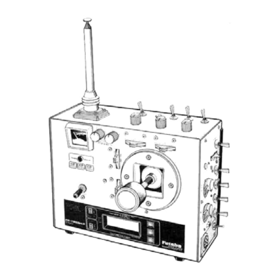
- Page 1 Futaba DIGITAL PROPORTIONAL RADIO CONTROL SINGLE STICK PULSE CODE MODULATION SYSTEM D60421...
-
Page 2: Table Of Contents
Thank you for purchasing a Futaba digital proportional radio control set. Please read this manual carefully before using your set. When reading this manual, refer to the foldout at the end of this manual. CONTENTS FEATURES ........ -
Page 3: Features
•FEATURES The FP-8SSHP is a digital proportional R/C set with PCM (Pulse Code Modulation) for helicopters. The system is extremely noise and dead-point resistant digital proportional R/C sets with a micro- processor in the transmitter and receiver. The FP-8SSHP was specially developed for FAI RC aerobatics F3C use. -
Page 4: Contents And Ratings
•Futaba low-power custom 1C provides high •Microprocessor-controlled servo hold function starting torque, narrow dead band, and excel- eliminates erroneous operation when the lent trackability. -
Page 5: Transmitter
•TRANSMITTER High This section explains the operation of the transmitter controls when the servo reversing switches are in the normal position. When the Servo throw by Servo throw by reversing switches are in the reverse position, throttle lever throttle trimming servo operation is the opposite of that describ- (30% of total ed here. - Page 6 14. Aileron dual rate switch 15. Elevator dual rate switch Aileron dual rate ON-OFF switch. When set to the • Elevator dual rate ON-OFF switch pull position dual rate is turned on, and when Similar to aileron dual rate, the elevator deflec- set to the push position, dual rate is turned off.
- Page 7 (19) Idle up 1 switch ( 1 switch) Right ON, Left OFF. Throttle servo (20) Idle up 1 ratcheted knob (1 knob) •When the 1 switch [ 1 9] is set to ON, the throttle servo "stop position" (idle up amount) can be adjusted with this knob.
- Page 8 22 Hovering throttle ratcheted knob 24 Monitor lamps •Trims the throttle servo independently from the pitch control servo (without regard to mixing). Fig. 14 Lamp ® Since the throttle servo can be trimmed without interfering with other mixing, this knob is very convenient when trimming the throttle while hovering.
- Page 9 25 Rotative open gimbal stick • Rotative open gimbal stick allows setting of the operating direction of the stick within a range of ±34 degrees by losening screws 1 to 4 in the figure 1/2 turn and turning the stick grille. •...
- Page 10 27. Tachometer/timer The tachometer/timer has the following func- 2. UP TIMER • 0 to 60 minutes with seconds displays. tions: 3. DOWN TIMER 1. Tachometer •60 to 0 minutes with seconds display •Measurement by external sensor. 4. INTEGRATING TIMER •Two blade propeller specifications. •...
-
Page 11: Operating Instructions
OPERATING INSTRUCTIONS Tachometer Set the tachometer/times POWER switch to ON. appears on the display. Next, press the MODE SEL key s w i t c h a t the upper-right corner three times. The display changes to the tachometer mode is selected. Hold the sensor about 20 to 30 cm from the rotating propeller (two blade). -
Page 12: Alarm Setting
Fig. 23 MODE SEL KEY SW. 2 UP TIMER Set the tachometer/timer POWER switch to ON. second from 10 seconds before the end of the is displayed. Next, press the MODE.SEL count-down, the same as the UP TIMER. key switch at the upper right-hand corner one time. The display changes to , and the UP TIMER mode is selected. - Page 13 29 Charging and DSC (Direct Servo •Normally charge the battery for about 15 hours. When the battery has not been used for some time, Controller) connector discharge it 2 to 3 times before charging. This connector is used as both the internal Nicad (Leaving the battery discharged for a long time will battery charging connector and the DSC con- lower the battery capacity and shorten the battery...
-
Page 14: Transmitter Rf Module
30 Power switch 35 Transmitter RF module Transmitter lock-type power switch. To turn the switch Change this module to switch frequency among on and o f f , pull the knob forward and set it to the de- different bands. sired position. - Page 15 37 Back cover 2. LINEAR-VTR switch To operate the trimmers and switches on the trimmer This switch switches the travel linearity panel [38] , remove this cover as shown in Fig. 28. of the aileron servo when the aileron dual rate switch [14] is in the OFF posi- tion.
- Page 16 B Pitch A Inverted flight low-side trimmer 3 High side pitch trimmer. B Inverted flight high-side trimmer Adjusts the high side pitch • The inverted flight function from about 60% of the full can be turned on and off throw of the pitch control with the [c] inverted flight servo as shown in Fig.
- Page 17 4. Normal pitch trimmer 12. Throttle hold switch [23] Adjusted to match normal fail safe switch flight. •When this switch is set to 5. This trimmer sets the low T.HOLD position, pitch (minus pitch) when the the throttle hold func- throttle hold switch [23] is tion operates and...
- Page 18 E. Elevator Rudder servo 23. Elevator dual rate trimmer This trimmer adjusts the elevator servo throw when Settable within the elevator dual rate switch [15] is set to ON. It has this range by the same functions as the aileron dual rate trimmer trimmer [16] .
- Page 19 G. Cyclic Corrective Pitch Mixing (optional) CCP mixing is performed after the helicopter correc- tive pitch and cyclic pitch control systems are electri- cally mixed. Since direct linkage from the servo to the swash plate is possible by using CCP mixing, the model can be made lighter by eliminating the intermediate mechanism.
- Page 20 H. Servo reversing switches •USING ATV (Aileron ATV These switches reverse the direction of the servos. taken as an example) They are very convenient when connecting the linkage. 1 First, set switch [K] [35] to the ATV side. Fig. 49 2 Next, set CHANNEL SELECT switch [J] [34] to the Rudder...
- Page 21 Each servo moves to the neutral position except •When switch [35] is switch to TEST-B. all the servos the throttle servo which moves to the slow position operate linearly over their full travel. (Channel select that was just set. switch [34] in TEST-ALL position at this time.) Only 6 Pail safe for all channels can be set with one touch the servos set at the channel select switch are oper- by setting the sticks and switches of the all channel...
-
Page 22: Function Select Switch
K Function select switch J Channel select switch •This switch selects ATV, FS, servo test, reset, and •This switch selects the channel to be set by ATV or BFS memory setting as described at [I] ATV/FS FS, when used in conjunction with item [1] ATV/FS button. -
Page 23: Receiver And Servos
After 36 seconds, the set reenters the B.F.S. •The crystal can be changed from the outside mode. When the set enters the B.F.S, state, immediate- of the receiver case. Always use the Futaba ly land the aircraft. transmitter/receiver matched crystal set to change the band. - Page 24 PCM RECEIVER FP-R118GP Receiver, servo switch, and battery connections Antenna wire Antenna wire AEC-3 Extension cord Crystal PCM receiver FP R118GP Fig. 56 Error lamp • System checking can be performed with this lamp. •When the receiver and servo side Nicd is connect- ed and this LED is on, radiowaves are not being received from the transmitter, check to be sure the frequency is correct.
- Page 25 Aileron servo 8SSHP 4 servos Elevator servo Throttle servo Rudder servo (When a rate gyro is used, this servo connects to the receiver through the rate gyro.) Landing gear servo, or rate gyro output switching connector Pitch control servo Fig. 57 Connected servo (rudder servo for helicopter) neutral position trimmer.
- Page 26 •General adjustments 1 1 . Start the engine. After needle adjustment, hover the helicopter, trim the ailerons and elevators, and Make the basic fuselage linkages and adjust- make the main rotor pitch larger during the next ments according to the helicopter manufac- hovering with the fuselage linkages.
-
Page 27: Aircraft Adjustments
AIRCRAFT ADJUSTMENTS •Revolution Mixing Compensation Ad- •IDLE UP 1 ADJUSTMENT justment Hover and check the throttle lever hovering posi- tion. When high speed level flight is performed with a heli- 2 Stop the engine, set the throttle lever to the hover- copter, the tail rotor reverse torque required is small, ing position, and set the idle up 1 knob [20] to... - Page 28 4. Adjust trimmer [8] so the engine stops (throttle •IDLE UP 2 ADJUSTMENT fully closed) when entering auto-rotation and when switch [23] is in the ON position and idles (throttle slightly open) during practice. 5 Adjust the maximum pitch when switch [23] is set 1 .
- Page 29 FP-T8SSHP INVERTED FLIGHT SPECIFICATIONS HANDLING PRECAUTIONS • When the [C] inverted flight FS switch at the rear panel trimmers is switch- ed to the INVERT position, normal flight <-> inverted flight switching,can be performed with the Inverted flight ON-OFF switch. •...
- Page 30 • The inverted flight function can be turned on and off with the [C] inverted flight FS switch on the trimmer panel at the back of the set. * INVERT: Inverted flight function ON : Inverted flight function OFF •When the [C] switch is in the INVERT (function ON) position, normal flight <-> inverted flight switching can be performed with the [26] Inverted flight ON-OFF switch at the side top corner of the transmitter.
- Page 31 INVERTED FLIGHT PREPARATIONS • Set the [C] inverted flight FS switch on the trimmer • After adjusting normal flight, adjust inverted flight. panel at the back of the set to the INVERT position. * Before flight, set the [26] switch to the back posi- •...
-
Page 32: Transmitter Controls
TRANSMITTER 22 Hovering throttle ratcheted knob CONTROLS 8 CH8 switch 33 Rudder button 7 CH7 Knob 31 Antenna 21 Idle up 2 switch 17 Revolution mixing up side 20 Idle up 1 ratcheted knob ratcheted knob 19 Idle up 1 switch 18 Revolution mixing 23 Throttle hold switch down side... - Page 33 TRANSMITTER CONTROLS Stick all of the packed non-slip pads at the positions desired by the customer. Fig. 2 Non-slip pad 38 Trimmer panel 37 Back cover A Ailerons H Servo reversing switches J Channel E Elevators CThrottle selector F 2nd ATV Fig.
-
Page 34: Splined Horn And Frequency Channel No. Flag Color
Purple-Blue 75.750 Purple-Grey 75.790 Grey.Black 75B30 Grey-Red 75fl70 • Futaba paired crystals are precisely matched. 53MHz • Aircraft/Car/Boat • FCC Amatuer License Required Always use a Futaba crystal set (transmitter, 53.100 Black/Brown 53.200 Black/Red receiver) when changing the frequency. 53.300... -
Page 35: S130 Exploded Views
S130 Nameplate S60101 GUARANTEE Your NEW FUTABA Digital Proportional R/C system is guaranteed against defacts in workmanship and material for 180 days from the date of purchase when the attached registration card is returned to us within ten days of purchase. -
Page 36: Factory Repair Service
7. Include a packing list of all items being returned, and double check to make sure that all items are packed. 8. Upon receipt of your equipment al the Futaba factory, an estimate of the cost of repair (over $25 00 only) will be sent to you- Your equipment will then be repaired and returned to you upon receipt of payment or C O.D.
Need help?
Do you have a question about the FP-8SSHP and is the answer not in the manual?
Questions and answers