Advertisement
Quick Links
Advertisement

Subscribe to Our Youtube Channel
Related Manuals for FUTABA FP-8JN


Summary of Contents for FUTABA FP-8JN
- Page 1 Futaba DIGITAL PROPORTIONAL RADIO CONTROL...
- Page 2 THANK YOU for purchasing a Futaba digital proportional radio control set. Please read this manual thoroughly before using your new set. CONTENTS Features................ Contents and Ratings ........... Transmitter Controls ............Using the Transmitter ........... Using the Receiver and Servos ........
- Page 3 • FEATURES This radio control set has been developed for FAI RC acrobatic F3A use. Please read this manual thoroughly before using your set. Transmitter FP-T8JN Receiver FP-R8J •The transmitter employs a module system. The •Module type. The frequency band and modulation frequency band and modulation method can be method can be changed with one touch, the same changed with one touch.
- Page 4 • SET CONTENTS AND RATINGS Set name FP-8JN Transmitter FP-T8JNx1 Receiver FP-R8JX1 Servo FP-S121x4 Landing gear servo FP-S121Gx2 Switch R4-SWJx1 NiCd battery NR-4Hx1 Charger, extension cord, landing gear adapter, Accessories DSC cord, ribbon, horn, servo tray Transmitter FP-T8JN Servo FP-S121...
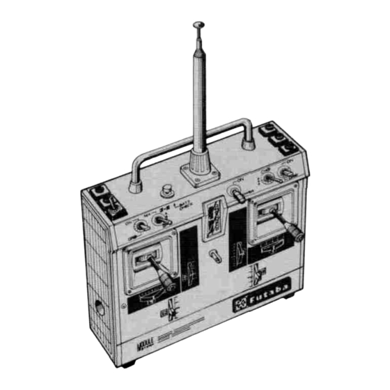
- Page 5 • TRANSMITTER CONTROLS Fig.1...
- Page 6 Purpose of switches and trimmers in Fig. 2 The numbers in circles represent the channel the throttle trim. Normally use at the LOW number. The channel numbers on the front of side. the transmitter correspond to the receiver Aileron ATV (Adjustable Travel Volume) R AIL, ATV-R This trimmer adjusts the connector output numbers.
- Page 7 Throttle button trimmer Elevator ATV U trimmer ELEV. ATV-U THROT The throttle servo is operated at This trimmer adjusts the elevator travel in the the position set by this trimmer by push- ing the throttle button. UP direction when the elevator reverse switch The total travel can be set at throttle stick is in the NORM position.
- Page 8 • USING THE TRANSMITTER Before using the transmitter, charge the NiCd battery. •Connect the DIN connector of the FBC-2L charger to the charging jack of the transmitter and the 3P connector to the receiver servo NiCd battery (NR-4H), and plug the charger into an AC110V outlet as shown in Fig.
- Page 9 when desiring to make the spin and other steering point, linkage is extremely simple. angles large, set it to ON and adjust the horn, ad- Dual travel is operative even at elevator and flap justers, and trimmers for level flight. mixing.
- Page 10 (NOTE) Always release CH7 switch •Using the aileron, elevator, throttle, and rudder (spoiler) of Fig. 1 before releasing reverses MIX switch when releasing mixing. (Devices which reverse the direction of operation of the servos) If these switches are released in the reverse There must be no play in the aircraft linkage direction.
- Page 11 • USING THE RECEIVER SERVOS Aileron servo...
- Page 12 •The receiver channel order is shown in Fig. 8. •All the servos can be controlled from the receiver Stick the channel tabs furnished with the set to (direct servo control system) by applying the the servo lead wires for identification. signals form the transmitter to terminal C of the •Use an extension cord matched to the fuselage.
- Page 13 Details Quantity Remarks Upper case Middle case Bottom case Pinion motor 1 st gear 2nd gear 3rd gear Final gear 2nd shaft Intermediate shaft Output shaft Spacer washer Seal ring Radial ball bearing M2x24 Pan head screw Truss screw M2x5 Motor Slider Volume...
- Page 14 • MODULES The frequency, frequency band, and modulation (AM, FM) of the J Module Series can be changed. The transmitting and receiving modules are availa- ble as a pair. EXAMPLE 1. : Switching from 27.195MHz to 27.045MHz Replace both the transmitting and receiving modules with the 27.045 MHz RF module.
-
Page 15: Factory Repair Service
7. Include a packing list of all items being returned, and double check to make sure that all items are packed. 8. Upon receipt of damaged equipment at the FUTABA factory, an estimate of the cost of repair will be sent to you. Your equipment will then be repaired and returned to you upon receipt of payment.
Need help?
Do you have a question about the FP-8JN and is the answer not in the manual?
Questions and answers