
Related Manuals for FUTABA FP-8SGAP


Summary of Contents for FUTABA FP-8SGAP
-
Page 1: Instruction Manual
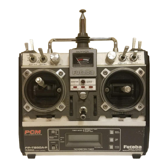
Futaba DIGITAL PROPORTIONAL RADIO CONTROL PULSE CODE MODULATION SYSTEM INSTRUCTION MANUAL FP-8SGAP PCM 8 CHANNELS, FOR F3A AIRCRAFT D60354... - Page 2 Thank you for purchasing a Futaba digital proportional radio control set. Please read this manual carefully before using your set.
-
Page 3: Table Of Contents
INDEX FOR TRIMMER PANEL FUNCTIONS TABLE OF CONTENTS Switch or Description Ref. Page GENERAL INFORMATION Trimmer Features ......Number Contents and Ratings . - Page 4 •FEATURES The FP-8SGAP was specially developed to use PCM (pulse code modulation) for FAI RC aerobatics F3A aircraft. It is an extremely noise and dead-point resistant digital proportional RC set with a microprocessor in the transmitter and the receiver. Please read this manual before using your set.
- Page 5 •Thick gold plated connector pins ensure positive • Futaba low-power custom 1C provides high start- ing torque, narrow dead band, and excellent contact and improve reliability against shock and vibration. The connector housing is polarized to trackability.
-
Page 6: Contents And Ratings
•CONTENTS AND RATINGS Ratings and specifications are subject to change without prior notice. FP-8SGAP Model Transmitter FP-T8SGAP x 1 with module FP-TF-FM FP-R118GPx 1 Receiver Servos FP-S130x4 SWH-5x 1 (R4-SWJx 1) Switch Nicd battery NR-4J x 1 Battery charger, landing gear adaptor, DSC cord, CHG adaptor, DSC-CHG... -
Page 7: Glossary Of Terms
This state of the art meth- quirements. This can be done by conveniently od makes many of the sophisticated functions of the FP-8SGAP possible, as well as providing far flipping a switch on the trimmer panel. Servo superior immunity to noise and interference than travel and neutral position are not affected. -
Page 8: Basic Transmitter Controls
PROGRAMMED MIXING FAIL SAFE Unidirectional mixing of any two channels desired The Fail Safe function moves servos to a pre-set is possible using the pin board and jumper con- position if the transmitter signal is lost or inter- nectors on the transmitter back panel. Either chan- rupted by strong interferrence. - Page 9 Monitor Lamps IMPORTANT: In all instructions on control functions. Items designated by a number inside a circle (For example 10 ) are transmitter controls normally accessable and operated in flight. Items designated by a number within a box (For example 10 ) are adjustment functions not operated while in flight.
- Page 10 Slantable stick adjusting screws Aileron Rudder The angle of the stick levers can be changed. MODE I Elevator Fig. 3 Fig. 5-A Turn with a Phillips screwdriver. The spring strength can be adjusted as desired by removing the transmitter back cover and turning the adjusting screw of each stick.
- Page 11 Mini stand Fail safe set button • Use this stand as shown • This pushbutton is used when in Figure when laying setting the Fail Safe servo transmitter down. positions (FS instructions This makes operation Page 25). easier and protects the RF module and transmitter back.
-
Page 12: Batteries And Charging Instructions
•BATTERIES AND CHARGING INSTRUCTIONS TX (transmitter) AC-120V Make this Battery charger connection when FBC-8B (2) using the DSC. DSC cord Antenna RX (receiver) Charging socket and DCS Receiver connector Female Male Install the accessory DSC.CHG cord Female (connector with tab) Female to the side of the Adaptor... -
Page 13: Tachometer/Timer Operation
•TACHOMETER/TIMER OPERATION LIQUID CRYSTAL DISPLAY Do not press the keys too quickly. Switches the range when used as a Press them at a speed of about once tachometer. LOW - 100 to 30,000 rpm. per second. HIGH -100to60,000 rpm Selects the tachometer/timer mode. Tachometer/timer power switch. -
Page 14: Operating Instructions
Make all speed measurements outdoors under OPERATING INSTRUCTIONS natural lighting. Accurate speed measurements cannot be made indoors under artificial lighting Tachometer because of the affect of the 50 or 60 Hz power. Set the tachometer/times POWER switch to ON. appears on the display. Next, press the MODE SEL key switch at the upper-right corner three times. -
Page 15: Alarm Setting
Note do not expose the liquid crystal display to direct sunlight for a long time. Selects the tachometer/ Switches the range when timer mode. used as a tachometer. This switch sets the alarm time. Tachometer/timer Memorize, start, stop, wer switch. and clear switch. -
Page 16: Receiver And Servos
•RECEIVER AND SERVOS 8SGAP 4 Servos Receiver, Servo Switch, and Aileron servo Battery Connections Elevator servo Throttle servo Rudder servo Landing gear servo Landing gear servo Flap servo Spoiler servo Pitch control servo Power switch SWH-5 (R4-SWJ) Fig. 19 Charging plug Pay careful attention to the polarity NR-4J of the connector. -
Page 17: Fp S130 And Fp-S130G Exploded Views
•FP-S130 AND FP-S130G EXPLODED VIEWS Fig. 23 Fig. 22 Part No. Pan Name Part No. PartName Upper case Upper case FCS-30 FCS-30G Middle case FCS-30G Middle case FCS-30 Bottom case FCS-30G Bottom case FCS-30 Motor S91243 Ball bearing S04130 Motor pinion S02461 Potentiometer 139995... -
Page 18: Splined Horns
•Also change the frequency flag when frequency is changed. •Futaba paired crystals are precisely matched. Always use a Futaba crystal set (transmitter, receiver) when changing the frequency. •It is illegal to change crystals of transmitter on the 72-75MHz bands in the U.S.A. -
Page 19: Basic Linkages And Installation
•BASIC LINKAGES AND INSTALLATION The FP-8SGAP has a servo reversing switch and ATV (Adjustable Travel Volume) for each channel. Mount the servos without regard to their direction. Select and link servo horns somewhat larger than those specified by the model manufacturer. -
Page 20: Using Atv (Adjustable Travel Volume)
•USING ATV (ADJUSTABLE TRAVEL VOLUME) GENERAL - ATV (Adjustable Travel Volume) deflection). Other aircraft may require slightly allows independent adjustment of servo maximum different RIGHT or LEFT aileron or rudder throw in each direction (without affecting the deflection to give equal response in each direction neutral position). - Page 21 CHANNEL SELECT SWITCH [48 Relationship among channel select switch • This switch 48 selects the channel when setting number, servo and reset. FS and HOLD functions. It also acts as the chan- At switch [49] FS SELECT, At switch [49] nel select switch for SERVO TEST function.
-
Page 22: 2Nd Atv (Conventional)
•2ND ATV (CONVENTIONAL) 2ND ATV is available on the aileron and elevator When the ATV trimmer is turned clockwise, the channels. This is the conventional type ATV and is steering angle increases. When the ATV trimmer is set using trimmers [34], [35]. [36], and [37] on the turned counterclockwise, the steering angle de- transmitter back panel. -
Page 23: Using Dual Rate (Aileron, Elevator, And Rudder)
•USING DUAL RATE (AILERON, ELEVATOR, AND RUDDER) Dual rate functions allow the flyer to alter the tings). At D/R ON, servo deflection is reduced by maximum servo travel (and therefore control sensi- a percentage set with the D/R trimmers. Dual rate tivity) during flight by using the appropriate rate adjustments always effect both directions of servo switch. -
Page 24: Rudder Auto Dual Rate
•RUDDER AUTO DUAL RATE •This function automatically switches rudder D/R to ON as the throttle lever is moved from LOW to HIGH position. This allows a smaller rudder throw for precise inputs during rolling maneuvers (at HIGH throt- tle) and increased throw (at LOW throttle) during stall turns, taxing, etc. Safety Switch [31] is set to ACT. -
Page 25: Suggestions On Atv, D/R. And Vtr
•SUGGESTIONS ON ATV, D/R, AND VTR POINTS TO REMEMBER (ATV, D/R, VTR) •Servo maximum deflection is always determined by ATV. If no ATV is set, maximum travel is governed by the servo itself and is approximately 45 degrees in each direction from neutral. •When Dual Rate is ON, servo travel in each direction is reduced by the same percentage (adjustable using D/R trimmers). -
Page 26: Using Atl (Adjustable Throttle Limit)
•USING ATL (ADJUSTABLE THROTTLE LIMIT) The Throttle Trim Lever 19 affects the servo po- sition only when the throttle control stick is in the LOW (IDLE) position. HIGH throttle position HIGH SLOW remains unchanged. Adjustment of the throttle linkage is therefore very convenient. Use a servo horn that allows slightly more throw than needed. -
Page 27: Fs (Fail Safe) And Hold Functions
•FS (FAIL SAFE) AND HOLD FUNCTIONS HOW TO USE FS (FAIL SAFE) (THROTTLE CHANNEL AS AN EXAMPLE.) Set Function Select Switch 49 to FS SELECT. Fail Safe for all channels selected can be set Set transmitter and receiver power switches to with one touch by moving the sticks and switches of all the channels to the desired posi- ON and check servo movements. -
Page 28: Servo Test Functions
•SERVO TEST FUNCTIONS • The operation of the servos can be checked by • The servo test is started by pressing button [46]] setting the transmitter and receiver power and is stopped by pressing button 47. switches to ON. •When switch 49 is switched to TEST-A, the servos move half-side first and then, come back to neutral and repeat the other-half from chan- nel 1 to channel 8. -
Page 29: Aircraft With Variable Pitch Prop
•AIRCRAFT WITH VARIABLE PITCH PROP ADVANTAGES OF VARIABLE PITCH PROPELLER The variable pitch propeller offers such advantages as: 1. The desired speed and p u l l can be adjusted. Linkage Fig. 50 2. Speed matched to the engine is obtained. 3. - Page 30 Pitch zero does not have an air braking affect. If the engine is running at a speed of 3000 ~ 4000 Pitch 11 rpm, the air braking effect will not appear if the (maximum) propeller diameter is too small. Adjust the throttle so the pitch is positive and the engine idles when switch II is set to the OFF Pitch control position.
-
Page 31: Throttle Position Trimmer
•THROTTLE POSITION TRIMMER Throttle -> pitch control • (B) Throttle -> pitch control mixing mixing The pitch control servo mixing point can be set This is the start position setting to an arbitrary point between throttle lever 3 trimmer when M rudder auto dual maximum slow and medium slow. -
Page 32: Elevator/Flap Mixing
•ELEVATOR/FLAP MIXING ELEVATOR -> FLAP MIXING • Elevator -> Flap (2 -> 6) mixing is unidirectional with elevator (CH2) acting as the Master chan- • Switch 10 : ACT nel. This function can be helpful in looping, • Switch 18 : T R I M square cornered, and circular acrobatic maneu- vers. -
Page 33: Aircraft With Flaps And Spoilers(Airbrake)
•AIRCRAFT WITH FLAPS AND SPOILERS(AIRBRAKE) Set Control Switch 10 to ON and adjust the Connect the Flap servo to CH6 and the Spoiler flaps as shown in Fig. 62 with Trimmer 2 0 . servo to CH7 on the Receiver. Set Switch [32] Adjust the spoiler servo travel with Memory to ON. -
Page 34: Snap Roll Switch
•SNAP ROLL SWITCH (TIMER IS OPTIONAL) •When this function is used, snap rolls can be SNAP ROLL TIMER (OPTION) performed by pushing the Snap Switch 13 . Snap roll directions can be set using Control Switches These are the snap roll time setting 34 and 35 . - Page 35 EXAMPLE 1. Fig. 69. AILERON -> RUDDER MIXING • This function is sometimes referred to as"CAR" (Coupled Ailerons and Rudder) and is useful on sailplanes and certain scale models where aileron and rudder must be used together for coordinated turns. Connector 4 designates the Master channel and is set vertically at the CH1 (Aileron) posi- tion.
-
Page 36: Mutual (Bi-Directional) Mixing (Flpron, Elevn, V Tail, Diff)
•MUTUAL (BI-DIRECTIONAL) MIXING (FLPRON, ELEVN, V-TAIL, DIFF) Aileron + flap (FLPRON), aileron + elevator (ELEVN), rudder + elevator (V.TAIL), and aileron differential (DIF) mixing can be selected with a switch. FLPRON (AILERON + FLAP) •This function allows the use of flaps on aircraft •The Flap function can be operated by using the with full length "strip"... - Page 37 ELEVN (AILERON + ELEVATOR) • This type of mixing can be used with tailless and delta wing aircraft and flying discs. • Install and connect the servos as shown in Fig. 75. Always connect the Right side servo to CH1 (Aileron).
Need help?
Do you have a question about the FP-8SGAP and is the answer not in the manual?
Questions and answers