
Related Manuals for twin busch TW125M


Summary of Contents for twin busch TW125M
- Page 1 Manual 2-post lift garage model / TW242GE & Page | 1 Misprints, errors and changes excepted.
-
Page 2: Table Of Contents
Manual for the TW125M / TW125F 1-post lifts Table of contents 1. General information ..........................1 2. Identification of the instructions for use ....................1 3. Technical data ............................1 4. Modification of the product ......................... 2 5. Safety-related information ........................2 5.1 Safety instructions ............................ - Page 3 Manual for the TW125M / TW125F 1-post lifts 13.4 Circuit diagram 230 V ..........................31 13.5 Hydraulic diagram ..........................32 13.6 Hydraulic system............................. 33 13.7 Spare parts list ............................34 Further attachment: ⋅ EU Declaration of Conformity TW125M_TW125F_1-Post_Lift_Instruction_manual_uk_03_20250110.pdf Version: -03, 10.01.2025...
- Page 4 Manual for the TW125M / TW125F 1-post lifts Important information TW125M: ASSEMBLY You can find the assembly video for this lift on YouTube: https://www.youtube.com/watch?v=kMNY3OYO-JQ or scan the QR code. PRODUCT PRESENTATION You can find the product presentation video for this lift on YouTube: https://www.youtube.com/watch?v=i8A0glNR9J8...
- Page 5 Manual for the TW125M / TW125F 1-post lifts Important information TW125F: ASSEMBLY You can find the assembly video for this lift on YouTube: https://www.youtube.com/watch?v=IUW-nBUQMnI or scan the QR code. fi d th thi lift PRODUCT PRESENTATION You can find the product presentation video for this lift on YouTube: https://www.youtube.com/watch?v=rbsomPAF8h4...
- Page 6 24/7 Service Center: Our 24/7 Self-Service Center is a mobile website designed for self-diagnosis of issues with your Twin Busch lift. Here, we provide an extensive video collection covering a wide range of relevant topics for your Twin Busch lift, from fine-tuning and maintenance to component replacement.
-
Page 7: General Information
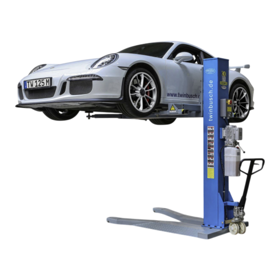
1. General information The new TW125M model is ultra-flat, with a frame height of just 85 mm and a swivel height of 98 mm. This makes it one of the flattest 1-post lifts on the market. Ideal for confined spaces, it can be moved as easily as a pallet truck and can be used on any level, sufficiently firm floor, e.g. -
Page 8: Modification Of The Product
The manufacturer accepts no liability for improper installation, operation or overloading. Improper use also invalidates the CE certification and the validity of the certificate. If you require any changes, please contact your dealer or the expert staff at Twin Busch GmbH beforehand. 5. Safety-related information In the event of improper installation, improper operation, overloading or unsuitable ground conditions neither the manufacturer nor the seller will accept liability. - Page 9 Manual for the TW125M / TW125F 1-post lifts ⋅ The vehicle's engine must be switched off. ⋅ The lift may only be put into operation when the vehicle is properly aligned. Only lift the vehicle at the point approved by the manufacturer and make sure that the transport mechanism is secured (release the pressure so that the lift rests firmly on the ground).
-
Page 10: Warnings And Symbols
Manual for the TW125M / TW125F 1-post lifts 5.2 Warnings and symbols All warnings are clearly visible on the lift to ensure that the user uses the device in a safe and appropriate manner. uses the device in a safe and appropriate manner. The warning labels must be kept clean and replaced if they are damaged or missing. -
Page 11: Conformity With The Product
Manual for the TW125M / TW125F 1-post lifts 6. Conformity with the product The TW125M and the TW125F are CE-certified and compliant with the Machinery Directive 2006/42/EC, fulfilling the standards EN 1493:2022, EN 60204-1:2018 (look at: EU Declaration of Conformity, at the end of the user manual). - Page 12 Manual for the TW125M / TW125F 1-post lifts Overview/designation Safety catches Support arm Limit switch Pull-out arm Pull-out arm Recording Support arm Page | 6 Misprints, errors and changes excepted.
-
Page 13: Structure Of Lifting Platform
Manual for the TW125M / TW125F 1-post lifts 8. Structure of lifting platform 8.1 Assembly instructions TW125M 1) Remove the packaging and take out the box containing the accessories and cover plates. Read and understand the operating instructions before proceeding. - Page 14 Manual for the TW125M / TW125F 1-post lifts 6) In the next step, place the column on the base. To do this, lift the column again with the motorised crane to align it. Align the column so that the holes are on top of each other after the column has been erected.
- Page 15 Manual for the TW125M / TW125F 1-post lifts For installation, the two loose cables for the limit switch must be fed from the column into the control unit. The control unit can then be screwed onto the column. Illustration: Limit switch 10) Please note that the following electrical installation may only be carried out by a qualified electrician! After installing the switch box, remove the plastic protection from the electrical connectorcrossbar.
- Page 16 Manual for the TW125M / TW125F 1-post lifts connections. It does not matter which motor cable is connected to which of the two connections. And don't forget to put the washers back on at this point. The box can then be screwed back together.
- Page 17 Manual for the TW125M / TW125F 1-post lifts 16) The previously unscrewed bolts are then reinserted. These bolts must also be tightened crosswise with a torque of 200 Newton metres. The assembly is now almost complete. Illustration: To finish the assembly 17) Raise the platform a little to remove the remaining packaging.
-
Page 18: Assembly Instructions Tw125F
Manual for the TW125M / TW125F 1-post lifts 8.2 Assembly instructions TW125F 1) Remove the packaging and take out the box containing the accessories and cover plates. Read and understand the operating instructions before proceeding. 2) Lift the column slightly using a suitable lifting sling so that it cannot tip over during unpacking. If you do not have a motorised crane or other lifting device available, we recommend using at least 3 strong people for the assembly. - Page 19 Manual for the TW125M / TW125F 1-post lifts 6) Now remove the packaging from the base plate. Move the base plate to its future position. Before further assembly, the platform should now be anchored with the heavy-duty anchors supplied. To do this, place an anti-slip mat on the base plate.
- Page 20 Manual for the TW125M / TW125F 1-post lifts 9) Next, the sling is moved further towards the lower end of the column for alignment. We push the column a little further so that the lower end stands on the non-slip mat when it is lowered. For your own safety, we recommend that you erect the column with at least three people or using aids such as a forklift truck or assembly crane.
- Page 21 Manual for the TW125M / TW125F 1-post lifts 12) Let us now turn our attention to the motor unit. Put it to one side and prepare the bolts for hanging. Place a bolt and nut on the top right and left of the motor unit. The motor unit can now be attached to the column and the two lower bolts each fitted with a nut.
- Page 22 Manual for the TW125M / TW125F 1-post lifts 14) To do this, we first open the box on the motor unit. There we open the two upper right terminals to which the red test cables are connected. Remove the red test cables that lead out of the box, but please note exactly where they were connected.
-
Page 23: Test Points After Assembly
Manual for the TW125M / TW125F 1-post lifts 17) Ensure that your socket has a slow-blow fuse with 16A Type C. Switch on the platform and lift it until the holes on the lifting carriage and the support arm unit are aligned. Now we can screw both parts together with the black bolts removed earlier. -
Page 24: Commissioning
Manual for the TW125M / TW125F 1-post lifts 9. Commissioning 9.1 Safety precautions a) If the safety devices are defective or show any abnormalities, the lifting platform must not be operated under any circumstances! b) Check all connections of the hydraulic lines for tight fit and proper functioning. If there are no leaks, a lifting operation can be started. -
Page 25: Lifting And Lowering Process (Using The Example Of A Mobile Post Lift With Manual Unlocking)
Manual for the TW125M / TW125F 1-post lifts 9.4 Lifting and lowering process (using the example of a mobile post lift with manual unlocking) 1. Drive the car to be serviced into position and switch off the motor. 2. Raise the post lift slightly by moving the swivelling handle (steering lever) up and down (like a pallet truck). - Page 26 Manual for the TW125M / TW125F 1-post lifts You can adjust the support arms as follows: Pull the safety latches; you can now adjust the support arms. Release the safety latches to lock the support arm. 8. Stop the lifting process and make sure that the vehicle is correctly and securely aligned.
-
Page 27: Operation / Diagrams
Manual for the TW125M / TW125F 1-post lifts 12. After final alignment and checking for tightness, press the lever switch again (under the on/off switch) and hold it down until the desired height is reached. 13. Never let the vehicle out of your sight during the raising and lowering process. -
Page 28: Troubleshooting And Rectification
10. Troubleshooting and rectification Please note: Do not hesitate to contact the expert staff at Twin Busch GmbH if you are unable to rectify a fault yourself. We will be happy to help you solve the problem. In this case, please document the fault and send us pictures and a precise description of the fault so that we can identify and rectify the cause as quickly as possible. -
Page 29: Maintenance And Troubleshooting
Manual for the TW125M / TW125F 1-post lifts 11. Maintenance and troubleshooting Regular maintenance of your lift will ensure a long and safe service life. Suggestions for maintenance intervals and the activities to be carried out are listed below. How often you service your lift depends on the ambient conditions, the degree of soiling and, of course, the stress and load on the lift. -
Page 30: Eliminate Fault
Manual for the TW125M / TW125F 1-post lifts 11.6 Eliminate fault No power Check power supply Three-phase connection may be connected incorrectly (400 V variant). (Change the connection and try again). The lift raises, but not up to the maximum load of 2500 kg. -
Page 31: Behavior In The Event Of An Incident
If the lift malfunctions, simple faults may be the cause. Use the following list for troubleshooting *). If the cause of the error is not listed or cannot be found, please contact the expert Twin Busch GmbH team. Never attempt to carry out repairs yourself, especially on safety devices or electrical system parts. -
Page 32: Appendix
Manual for the TW125M / TW125F 1-post lifts 13. Appendix 13.1 Dimensions of the TW125 M lift Page | 26 Misprints, errors and changes excepted. -
Page 33: Dimensions Of The Tw125 F Lift
Manual for the TW125M / TW125F 1-post lifts 13.2 Dimensions of the TW125 F lift Page | 27 Misprints, errors and changes excepted. -
Page 34: Foundation Requirements And Working Area
Manual for the TW125M / TW125F 1-post lifts 13.3 Foundation requirements and working area Requirements for the concrete: - Concrete C20/25 according to DIN 1045-2 (previous designation: DIN 1045 concrete B25). - The floor must be level and have a flatness of less than 5 mm/m. - Page 35 Manual for the TW125M / TW125F 1-post lifts TW125 M (Mobile) The surrounding soil must be suitable for the load, e.g. no sandy soils, etc. No soft surfaces (e.g. asphalt) Caution with tiles (clarify substrate condition), possible risk of slipping...
- Page 36 Manual for the TW125M / TW125F 1-post lifts Anchor bolt fastening Washer Base plate (lifting platform) Thread (anchor bolt) Concrete Tightening torque of the anchor bolts is: 80 Nm Page | 30 Misprints, errors and changes excepted.
- Page 37 Manual for the TW125M / TW125F 1-post lifts 13.4 Circuit diagram 230 V Transformer Indicator light Fuse Motor contactor Main switch Switches Push button Circuit diagram 230 V TW 125 M, TW 125 F (C) Twin Busch GmbH 27.01.2016 Page | 31...
- Page 38 Manual for the TW125M / TW125F 1-post lifts 13.5 Hydraulic diagram Cylinder Drain valve Electric pump Page | 32 Misprints, errors and changes excepted.
-
Page 39: Hydraulic System
Manual for the TW125M / TW125F 1-post lifts 13.6 Hydraulic system 1. Master cylinder 2. Secondary cylinder 3. Electromagnetic drain valve 4. Throttle valve 5. Motor 6. Clutch 7. Gear pump 8. Non-return valve (one-way valve) 9. Pressure relief valve (max.: 19.4 Mpa) 10. - Page 40 Manual for the TW125M / TW125F 1-post lifts 13.7 Spare parts list Page | 34 Misprints, errors and changes excepted.
- Page 41 Manual for the TW125M / TW125F 1-post lifts S/N. Designation Illustration QTY. Spec. TW 125-1 Column cover TW 125-2 Limit switch TW 125-3 Control box TW 125-3.1 (1) Main switch 20A TW 125-3,1 (2) Transformer BK-30 TW 125-3.1 (3) Button...
- Page 42 Manual for the TW125M / TW125F 1-post lifts TW 125-4 Screw M10*30 TW 125-5 Nut M10 TW 125-6 Manual pump TW 125-7 Chassis mobile TW 125-8 Bolt chassis TW 125-9 Axle sleeve TW 125-10 Strut mobile TW 125-11 M12*20 screw...
- Page 43 Manual for the TW125M / TW125F 1-post lifts Page | 37 Misprints, errors and changes excepted.
- Page 44 Manual for the TW125M / TW125F 1-post lifts S/N. Designation Illustration QTY. Spec. TW 125-15 Chain roller TW 125-16 Bearing 30*50 TW 125-17 Nut M27*15 TW 125-18 Roll holder TW 125-19 Axle to roller Screw TW 125-20 M6*12 TW 125-21...
- Page 45 Manual for the TW125M / TW125F 1-post lifts Page | 39 Misprints, errors and changes excepted.
- Page 46 Manual for the TW125M / TW125F 1-post lifts S/N. Designation Illustration QTY. Spec. TW 125-31 (1) Cylinder barrel TW 125-31 (2) O-ring 69*5.3 TW 125-31 (3) Limiting valve TW 125-31 (4) Cylinder cap TW 125-31 (5) Dust seal Ф45 TW 125-31 (6)
- Page 47 Manual for the TW125M / TW125F 1-post lifts S/N. Designation Illustration QTY. Spec. TW 125-32 Release lever TW 125-32 Dowel pin Ф4*30 TW 125-33 Locking bolt TW 125-34 Page | 41 Misprints, errors and changes excepted.
- Page 48 Manual for the TW125M / TW125F 1-post lifts TW 125-35 Handle TW 125-35 (1) Plastic ball TW 125-36 Lifting carriage TW 125-37 PA glider TW 125-38 Cross arm left/right Extension for cross TW 125-39 Extension for TW 125-39.1 Cross arm/Ultra...
- Page 49 Manual for the TW125M / TW125F 1-post lifts TW 125-44 Spring Unlocking support TW 125-45 TW 125-46 Recording disc TW 125-46 (1) Rubber pad TW 125-46 Rubber pad/Ultra (1,1) TW 125-47 Main support arm TW 125-48 Screw M16*40 TW 125-49...
- Page 50 Manual for the TW125M / TW125F 1-post lifts S/N. Designation Illustration QTY. Spec. TW 125-51 Base frame mobile TW 125-51.1 Base frame/fixed Fixed TW 125-51.2 Base frame/Ultra mobile TW 125-52 Roller axle TW 125-53 Circlip TW 125-54 Spacer ring TW 125-55...
Need help?
Do you have a question about the TW125M and is the answer not in the manual?
Questions and answers