Table of Contents
Advertisement
Quick Links
Advertisement
Table of Contents

Related Manuals for twin busch TW445E-G


Summary of Contents for twin busch TW445E-G
-
Page 2: Table Of Contents
Manual 4-post lift TW445E-G Table of contents 1. General information ..........................1 2. Identification of the instructions for use ....................1 3. Technical data ............................1 4. Modification of the product ........................2 5. Safety-related information ........................2 5.1 Safety instructions ............................2 5.2 Warnings and symbols .......................... - Page 3 Manual 4-post lift TW445E-G 13.5 Circuit diagrams ............................23 13.6 Parts description of the lift ........................27 13.7 Spare parts list ............................32 Further attachment: EU Declaration of Conformity ⋅ TW445E-G_4-Post_Lifts_Manual_uk_00_20241024.pdf Version: -00, 24.10.2024...
- Page 4 Manual 4-post lift TW445E-G TIPS & TRICKS In the "Tips & Tricks" section, we show you simple solutions, in videos to make your TWIN BUSCH® products even more efficient. to work. Our technical specialist will explain the exact steps to you. https://www.twinbusch.co.uk/Tips-Tricks:_:74.html...
-
Page 5: General Information
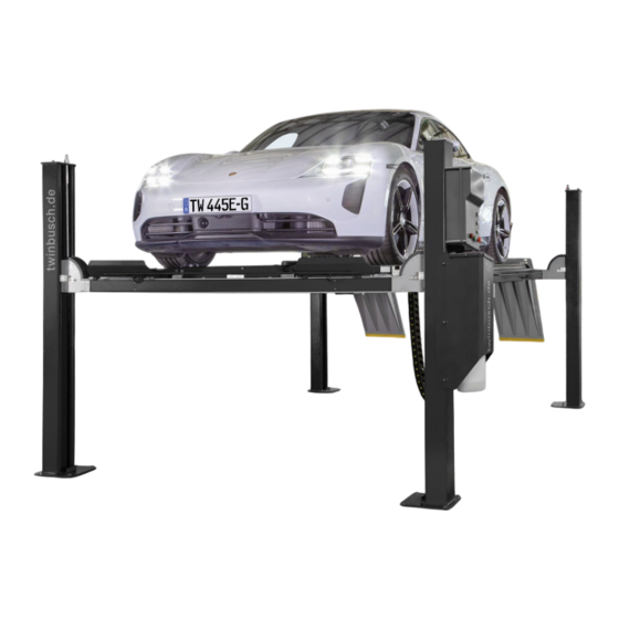
1. General information The TW445E-G 4-post lift generally consists of four posts, two beams, two platforms, a hydraulic oil cylinder and a power unit. It is driven by an electro-hydraulic system. The up and down movement of the platforms is controlled by the back and forth movement of the oil cylinder. -
Page 6: Modification Of The Product
The manufacturer accepts no liability for improper installation, operation or overloading. Improper use also invalidates the CE certification and the validity of the certificate. If you require any changes, please contact your dealer or the expert staff at Twin Busch GmbH beforehand. 5. Safety-related information Read the operating instructions carefully before operating the lift. -
Page 7: Warnings And Symbols
Manual 4-post lift TW445E-G 5.2 Warnings and symbols All warnings are clearly visible on the lift to ensure that the user uses the device in a safe and appropriate manner. The warning signs must be kept clean and replaced if they are damaged or missing. Please read the signs... -
Page 8: Safety Devices
Manual 4-post lift TW445E-G 5.3 Safety devices The lift is equipped with the following safety devices to ensure safe operation *): ⋅ Safety detents ⋅ Throttle valve in hydraulic line ⋅ Limit switch ⋅ Lifting carriage lock ⋅ Devices to prevent jamming and crushing (shaft protection, foot deflector) ⋅... -
Page 9: Compliance With The Product
Manual 4-post lift TW445E-G 6. Compliance with the product The TW 445E-G 4-post lift is CE-certified and complies with the Machinery Directive 2006/42/EC and fulfils the standards EN 1493:2022, EN 60204-1:2018 (see under: EU Declaration of Conformity, at the end of the instructions for use). -
Page 10: Structure Of Lifting Platform
Manual 4-post lift TW445E-G 8. Structure of lifting platform 8.1 Before installation Tools and equipment required: ⋅ Suitable lifting tool for bulky and heavy components ⋅ Hammer drill with ¾ drill bit ⋅ Chalk and tape measure, magnetic pump, 8 metre Ф15 horizontal pipe ⋅... -
Page 11: Assembly Instructions
Manual 4-post lift TW445E-G 8.3 Assembly instructions 1) Read and understand the operating instructions before proceeding. 2) Select a suitable location. The lifting platform should be mounted on a smooth and firm concrete floor. Ensure that the space around or above the lift is free of obstacles such as heating systems, building supports, electrical cables, etc. - Page 12 Manual 4-post lift TW445E-G 5) Use a crane to position the general parts according to the following plan. Note: The oil cylinder, the steel cable and the oil hose have already been attached to the main platform before packing. The wire rope, oil hose, safety lock etc. have already been attached to the carriers before packing.
- Page 13 Manual 4-post lift TW445E-G 6) Connect the carrier and the platform. First connect the main beam to the two platforms. Use M12*30 hexagon socket head bolt and M12 hexagon nut to fix the beam and platform through the holes. Note: You can adjust the distance between two platforms according to the situation, then fix the block plate on the platform.
- Page 14 Manual 4-post lift TW445E-G b) Lever the safety rack higher and move the column into the beam as shown below. Steel cable Safety interlock Sealing plate Sealing plate Column c) Remove the steel cable inside the support and connect it to the top of the column. To do this, use an M20 washer and a nut that are attached to the top plate of the column.
- Page 15 Manual 4-post lift TW445E-G 8) Secure the ramp with the shaft and split pins. Shaft Circlip Ramp 9) Install the control box and the hydraulic motor. a) Mount the hydraulic unit and disconnect the oil hose and the air hose from the main platform and connect them to the hydraulic block.
- Page 16 Manual 4-post lift TW445E-G b) Attach the switch box to the mains-side pillar and connect the cables. Illustration: Switch box 10) Fill the tank with approx. 80 % hydraulic oil. Only use clean and fresh oil! Hydraulic oil type: HLP 32 Page | 12 Misprints, errors and changes excepted.
-
Page 17: Checkpoints According To The Structure
Manual 4-post lift TW445E-G 11) Levelling Caution: No vehicle on the platforms when levelling! a) Switch on the appliance and press the "UP" button when the green power indicator lights up. Remove the screw cap from the centre inlet of the switch box and remove the rubber seal. -
Page 18: Commissioning
Manual 4-post lift TW445E-G 9. Commissioning 9.1 Safety precautions a) If the safety devices are defective or show abnormalities, the lift must not be put into operation under any circumstances! b) Check all connections of the oil hose. If there are no leaks, a lifting process can be started. -
Page 19: Lifting And Lowering Process Flow Chart
Manual 4-post lift TW445E-G 9.3 Lifting and lowering process flow chart Lifting process Lowering process Start Start Switch on the power Switch on the power Press the DOWN button Press the UP button (push-button) (push-button) Motor drives the gear pump The lift raises for approx. -
Page 20: Operating Instructions
Manual 4-post lift TW445E-G 9.4 Operating instructions 9.4.1 Lifting process 1. Read and understand the operating instructions before starting work. 2. Connect the power supply and switch the main switch to ON. 3. Park the vehicle with its centre of gravity in the middle of the platforms. -
Page 21: Troubleshooting
10. Troubleshooting Please note: Do not hesitate to contact the expert staff at Twin Busch GmbH if you are unable to rectify a fault yourself. We will be happy to help you solve the problem. In this case, please document the fault and send us pictures and a precise description of the fault so that we can identify and rectify the cause as quickly as possible. -
Page 22: Maintenance
Manual 4-post lift TW445E-G 11. Maintenance Regular maintenance of your lift will ensure a long and safe service life. Suggestions for maintenance intervals and the activities to be carried out are listed below. How often you service your lift depends on the ambient conditions, the degree of soiling and, of course, the stress and load on the lift. -
Page 23: Behavior In The Event Of An Incident
If the lift malfunctions, simple faults may be the cause. Use the following list for troubleshooting *). If the cause of the error is not listed or cannot be found, please contact the expert Twin Busch GmbH team. Never attempt to carry out repairs yourself, especially on safety devices or electrical system parts. -
Page 24: Appendix
Manual 4-post lift TW445E-G 13. Appendix 13.1 Packing list Description Drawing & Specification Hint Main platform FL-8448T-A5 Assistance platform FL-8448T-A6 Main girder FL-8448T-A3 Assistance bar FL-8448T-A4 Ramp FL-8448T-A5-B3 Foot guard FL-8448T-A5-B6 Main column FL-8448T-A1 Assistance column FL-8448T-A2 Expansion screw M18*160... -
Page 25: Foundation Requirements And Working Area
Manual 4-post lift TW445E-G 13.3 Foundation requirements and working area Requirements for the concrete: - Concrete C20/25 according to DIN 1045-2 (previous designation: DIN 1045 concrete B25). - The floor must be level and have a flatness of less than 5 mm/m. -
Page 26: Hydraulic Plan
Manual 4-post lift TW445E-G 13.4 Hydraulic plan 1. Cylinder 2. Emergency release valve 3. Throttle valve adjustable 4. Motor 5. Cutch 6. Pump 7. Non-return valve 8. Pressure relief valve 9. Throttle check valve 10. Spring-loaded non-return valve Name Quantity... - Page 27 Manual 4-post lift TW445E-G 13.5 Circuit diagrams Single-phase Page | 23 Misprints, errors and changes excepted.
- Page 28 Manual 4-post lift TW445E-G Three-phase Page | 24 Misprints, errors and changes excepted.
- Page 29 Manual 4-post lift TW445E-G Page | 25 Misprints, errors and changes excepted.
- Page 30 Manual 4-post lift TW445E-G Page | 26 Misprints, errors and changes excepted.
- Page 31 Manual 4-post lift TW445E-G 13.6 Parts description of the lift Page | 27 Misprints, errors and changes excepted.
- Page 32 Manual 4-post lift TW445E-G Page | 28 Misprints, errors and changes excepted.
-
Page 33: Specification
Manual 4-post lift TW445E-G Material Name Specification Material Notes Main column FL-8448ET-A1-B1 Welded GB/T819.1-2000 Secondary column FL-8448T-A2-B1 Welded Safety interlock FL-8448T-A1-B2 Welded Hexagon nut Standard GB/T 6170-2000 Steel cable L=9650 FL-8448T-A9 Standard Steel cable L=5020 FL-8448T-A9 Standard Steel cable L=3520... - Page 34 Manual 4-post lift TW445E-G Hexagon nut Standard Small slider FL-8448T-A7-B3 Nylon 1010 Phillips head screw M6*15 Standard GB/T819.1-2000 Oil sump FL-8448T-A19 Q235A Hexagon socket round-head M6*15 Standard GB/T 70.1-2000 screw Main girder FL-8448T-A3-B1 Welded Main safety rack FL-8448T-A3-B2 Welded Auxiliary safety rack...
- Page 35 Manual 4-post lift TW445E-G Joint M14*1.5/G1/4 Q235A Fuelling chain 50*30 Cover plate FL-8465T-A1-B7 Fixed frame FL-8465T-A1-B6 Limit switch 8108 Standard Hexagon socket round head M5*12 Standard GB/T 70.1-2000 screw Box 4 FL-8448T-A5-B7 Welded Expansion screw M16*180 Standard Mechanical parts Material...
- Page 36 Manual 4-post lift TW445E-G 13.7 Spare parts list S/N Material Name Specification Unit Qty Picture Mains switch LW26GS-20/04 Button Y090-11BN Mains display AD17-22G-AC24 Transformer JBK3-40VA 220V-24V Like point 7 Transformer JBK3-40VA 230V-24V Like point 7 Transformer JBK3-40VA 240V-24V Like point 7...
- Page 37 Manual 4-post lift TW445E-G S/N Material Name Specification Unit Qty Picture Emergency stop switch Y090-11ZS/red Control unit 190*430*135 Limit switch 8108 Electromagnet MQB3-10-20/AC24V system Hydraulic Material Name Specification Unit Picture Hydraulic block YF-1 (manual release) Coil of the solenoid valve...
- Page 38 Manual 4-post lift TW445E-G Material Name Specification Unit Picture Damping valve HCYF-C Hexagonal plug M14*1.5 connector Connection for M14*1.5-G1/4inside generator set swivel Clutch YL-A Gear pump CBK-F230 Gear pump CBK-F220 Like point 11 Oil pipe YX-B/270 Oil filter YF-C Oil return line...
Need help?
Do you have a question about the TW445E-G and is the answer not in the manual?
Questions and answers