
Subscribe to Our Youtube Channel
Related Manuals for twin busch Basic Series


Summary of Contents for twin busch Basic Series
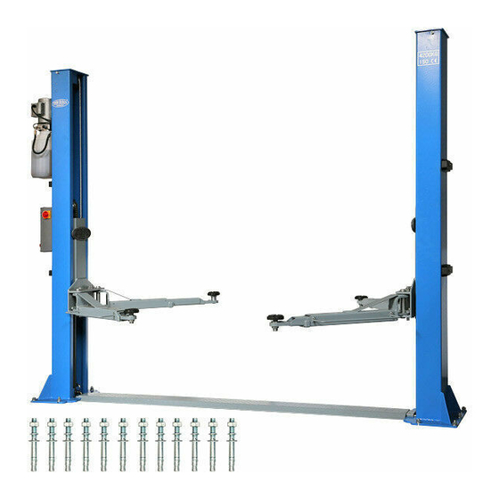
- Page 1 Manual 2-post lift garage model / TW242GE Page | 1 Misprints, errors and changes excepted.
-
Page 2: Table Of Contents
Manual of 2-post lift TW242E / TW242E-G Table of contents 1. General..............................1 2. Identification of the instructions for use ....................1 3. Technical data ............................1 4. Modification of the product ......................... 1 5. Safety-related information ........................2 5.1 Safety instructions ............................ 2 5.2 Safety equipment ............................ - Page 3 Manual of 2-post lift TW242E / TW242E-G 13.3 Diagram for floor fastening / foundation plan ..................27 13.4 Hydraulic system............................. 28 13.5 Control box (230V) ..........................29 13.6 Circuit diagrams ............................. 30 13.7 Detailed drawing and parts description of the lift .................. 33 13.8 Spare parts list ............................
- Page 4 Manual of 2-post lift TW242E / TW242E-G Important Information: ASSEMBLY You can find the assembly video for this lift on YouTube: www.youtube.com/watch?v=wVufUl57zkA or scan the QR code. PRODUCT PRESENTATION You can find the product presentation video for this lift on YouTube: www.youtube.com/watch?v=oPDXYQng7FU or scan the QR code.
- Page 5 24/7 Service Center: Our 24/7 Self-Service Center is a mobile website designed for self-diagnosis of issues with your Twin Busch lift. Here, we provide an extensive video collection covering a wide range of relevant topics for your Twin Busch lift, from fine-tuning and maintenance to component replacement.
-
Page 6: General
The manufacturer accepts no liability for improper installation, operation or overloading. Improper use also invalidates the CE certification and the validity of the certificate. If you require any changes, please contact your dealer or the expert staff at Twin Busch GmbH beforehand. Page | 1... -
Page 7: Safety-Related Information
Manual of 2-post lift TW242E / TW242E-G Safety-related information Read the operating instructions carefully before operating the lift. Keep the instructions in a safe place for future reference. Follow the instructions carefully to achieve the best performance from the machine and to avoid damage due to personal negligence. -
Page 8: Safety Equipment
Manual of 2-post lift TW242E / TW242E-G 5.2 Safety equipment The lift is equipped with the following safety devices to ensure safe operation *): ⋅ Safety catches ⋅ Throttle valve in hydraulic line ⋅ Limit switch ⋅ Support arm lock ⋅... -
Page 9: Warnings And Symbols
Manual of 2-post lift TW242E / TW242E-G 5.4 Warnings and symbols All warnings are clearly visible on the lift to ensure that the user uses the device in a safe and appropriate manner. The warning signs must be kept clean and replaced if they are damaged or missing. Please read the signs carefully and memorise their meaning for future use. -
Page 10: Load Distribution
Manual of 2-post lift TW242E / TW242E-G 5.5 Load distribution 6. Conformity with the product The TW 242E / TW 242E-G 2-post lift is CE-certified and complies with the Machinery Directive 2006/42/EC, the standard for low voltage 2014/35/EU and fulfils the standards Lifting platforms EN 1493:2022, Safety of machinery EN 60204-1:2018 (see under: EU Declaration of Conformity, at the end of the instructions for use). -
Page 11: Assembly Of The Lifting Platform
Manual of 2-post lift TW242E / TW242E-G 8. Assembly of the lifting platform 8.1 Before installation 8.1.1 Tools and equipment required ⋅ Suitable lifting tool for bulky and heavy components ⋅ Hammer, pliers ⋅ Phillips and slotted screwdriver ⋅ Set of Allen keys ⋅... - Page 12 Manual of 2-post lift TW242E / TW242E-G 4) Set up both columns. Align the main and secondary pillars with each other (outer edge of base plate to outer edge of base plate approx. 3436 mm) a) After unpacking, you must decide in which position (left or right in the direction of entry) you want to attach the main column with the power supply and the control unit.
- Page 13 Manual of 2-post lift TW242E / TW242E-G Fit the control unit or control box to the main pillar. Connect the electromagnet cables to the cable plugs (B) in the switch box. Electromagnet Y-cable (short) Switch box Y-cable (long) Plug connector (B) Plug connector (B) Plug connector (laid under the drive-over plate...
- Page 14 Manual of 2-post lift TW242E / TW242E-G Figure: Electromagnet release connections 7) Mounting the motor unit. Figure: Mounting the motor unit a) Make sure that all hose ends are clean and free of dirt. b) Connect the hydraulic lines as shown in the following illustration or in the hydraulic circuit diagram. c) Fit the two steel cables to secure the pressurised hydraulic hose so that it is not thrown around uncontrollably.
- Page 15 Manual of 2-post lift TW242E / TW242E-G Steel cable for securing Steel cable for securing Motor unit Hydraulic Hydraulic cylinder cylinder Line 2 Hydraulic Hydraulic Hydraulic management management management connection connection connection Line 1 Figure: Installing the hydraulic line Page | 10 Misprints, errors and changes excepted.
- Page 16 Manual of 2-post lift TW242E / TW242E-G 8) After installing the safety catches, connect the carriages to the steel cable. a) Align the carriages on both sides of the column approx. 800 mm above floor level b) Ensure that the safety catches on both sides of the column are engaged before you start installing the steel cables c) The carriages must be at the same height from the ground before you continue d) Pull in the steel cables as shown in the following illustration...
- Page 17 Manual of 2-post lift TW242E / TW242E-G 10) Fit the limit switch at the top of the main column as shown in the following illustration. Limit switch M4x12 Phillips head screw M4x12 Phillips head screw Connection to the control unit (A plug) Figure: Mounting the limit switch 11) Fit the drain coil and connect the plug connection C (plug) in the switch box.
- Page 18 Manual of 2-post lift TW242E / TW242E-G 12) Fit the protective covers for the hydraulic lines from bottom to top, making sure that the narrow opening faces upwards. Protective cover 13) Fitting the support arms a) Insert the support arms into the lifting carriages, paying attention to the interlocking of the anti- rotation blocks.
- Page 19 Manual of 2-post lift TW242E / TW242E-G 14) Filling the hydraulic system. The hydraulic oil tank has a capacity of approx. 10 litres. To ensure that the lift functions correctly, you should fill the oil tank to 80 % with hydraulic oil type: HLP 32. 15) Test run.
- Page 20 Manual of 2-post lift TW242E / TW242E-G 17) Fitting the drive-over plate. Drive-over plate Column Column 18) Checkpoints after assembly. Check Are the columns vertical to the floor? (90°) Are the two columns parallel to each other? Is the oil hose connected correctly? Is the steel cable correctly and firmly connected? Are all support arms correctly and firmly mounted? Are the electrical connections correct?
-
Page 21: Operating Instructions
Manual of 2-post lift TW242E / TW242E-G 9. Operating instructions 9.1 Safety precautions - If the safety devices are defective or show abnormalities, the lift must not be put into operation under any circumstances! - Check that all connections of the hydraulic lines are tight and functional. If there are no leaks, the lifting process can be started. -
Page 22: Flow Chart Of The Control Unit (Control Box)
Manual of 2-post lift TW242E / TW242E-G 9.3 Flow chart of the control unit (control box) Lowering process Lifting process Start Start Switch on the power Switch on the power Press the UP button (push-button) Press the DOWN button (push-button) Motor drives the gear pump The lift raises for approx. -
Page 23: Lifting And Lowering Process
Manual of 2-post lift TW242E / TW242E-G 9.4 Lifting and lowering process Lifting process: 1. Read and understand the operating instructions before starting work. 2. Connect the power supply and switch the main switch to ON. 3. Park the vehicle with its centre of gravity in the middle between the two pillars 4. -
Page 24: Emergency Drain In The Event Of A Power Failure
Manual of 2-post lift TW242E / TW242E-G 9.5 Emergency drain in the event of a power failure 1. When the lifting carriage is NOT sitting on the locks. a) Pull all electromagnets simultaneously and secure with cable ties to open the safety catches. Electromagnet Figure: Unlocking all electromagnets Actuate the manual drain (bayonet catch or twist lock) - Page 25 Manual of 2-post lift TW242E / TW242E-G 2. With the lifting carriage sitting on the locks. a) Unscrew the sealing plug to be able to connect the manual hydraulic pump (not included in the scope of delivery). Motor Hydraulic connection Sealing plugs (hydraulic connection) Oil tank...
-
Page 26: Troubleshooting And Rectification
10. Troubleshooting and rectification Please note: Do not hesitate to contact the expert staff at Twin Busch GmbH if you are unable to rectify a fault yourself. We will be happy to help you solve the problem. In this case, please document the fault and send us pictures and a precise description of the fault so that we can identify and rectify the cause as quickly as possible. -
Page 27: Maintenance
Manual of 2-post lift TW242E / TW242E-G 11. Maintenance Regular maintenance of your lift will ensure a long and safe service life. Suggestions for maintenance intervals and the activities to be carried out are listed below. How often you service your lift depends on the ambient conditions, the degree of soiling and, of course, the stress and load on the lift. -
Page 28: Annual Inspection Of The Parts
If the lift malfunctions, simple faults may be the cause. Use the following list for troubleshooting *). If the cause of the fault is not listed or cannot be found, please contact the expert Twin Busch GmbH team. Never attempt to carry out repairs yourself, especially on safety equipment or electrical system components. -
Page 29: Appendix
Manual of 2-post lift TW242E / TW242E-G 13. Appendix 13.1 Dimensions of the lift Page | 24 Misprints, errors and changes excepted. -
Page 30: Requirements Of The Foundation
Manual of 2-post lift TW242E / TW242E-G 13.2 Requirements of the foundation Requirements for the concrete: - Concrete C20/25 according to DIN 1045-2 (previous designation: DIN 1045 concrete B25). - Floor must be level and have a flatness of less than 5 mm/m. - Newly poured concrete must cure for at least 28 days. - Page 31 Manual of 2-post lift TW242E / TW242E-G The following must be observed for soil exposed to frost: In the case of frost exposure, the concrete must correspond to exposure class XF4, as dripping de-icing agent cannot be ruled out. This results in the following minimum requirements for concrete under frost stress: Exposure class: Maximum w/c: 0,45...
-
Page 32: Diagram For Floor Fastening / Foundation Plan
Manual of 2-post lift TW242E / TW242E-G 13.3 Diagram for floor fastening / foundation plan Page | 27 Misprints, errors and changes excepted. -
Page 33: Hydraulic System
Manual of 2-post lift TW242E / TW242E-G 13.4 Hydraulic system 1. Master cylinder 2. Secondary cylinder 3. Electromagnetic drain valve 4. Throttle valve 5. Motor 6. Clutch 7. Gear pump 8. Non-return valve (one-way valve) 9. Pressure relief valve (max.: 19.4 Mpa) 10. -
Page 34: Control Box (230V)
Manual of 2-post lift TW242E / TW242E-G 13.5 Control box (230 V) Page | 29 Misprints, errors and changes excepted. -
Page 35: Circuit Diagrams
Manual of 2-post lift TW242E / TW242E-G 13.6 Circuit diagrams Page | 30 Misprints, errors and changes excepted. - Page 36 Manual of 2-post lift TW242E / TW242E-G Page | 31 Misprints, errors and changes excepted.
- Page 37 Manual of 2-post lift TW242E / TW242E-G Page | 32 Misprints, errors and changes excepted.
-
Page 38: Detailed Drawing And Parts Description Of The Lift
Manual of 2-post lift TW242E / TW242E-G 13.7 Detailed drawing and parts description of the lift Spare part no. Name Specification Qty. Feature HEB0018 Steel cable L=8820mm FL8224-A6 Assembly M16 hexagon nut GB/T610-2000 Standard HEB0515 M16*173 anchor bolt Standard Page | 33 Misprints, errors and changes excepted. - Page 39 Manual of 2-post lift TW242E / TW242E-G Name Spare part no. Specification Qty. Feature E-HEB0184 Motor/hydraulic unit Assembly E-HEB0099 Oil line L=500 mm Assembly E-HEB0064 Hydraulic contra-angle Assembly E-HEB0100 Oil line L=2250 mm Assembly E-HEB0066 Cylinder connection (banjo) Assembly Sealing ring Standard E-HEB0066 Cylinder connection (banjo)
- Page 40 Manual of 2-post lift TW242E / TW242E-G Spare part no. Name Specification Qty. Feature E-HEB0013 Safety catch 8224E-A1-B2 Galvanised E-HEB0013-3 Screw to holder M6*16 GB/T818-2000 Standard M6*10 (cross recess) GB/T818-2000 Standard E-HEB0014 Electromagnet MQZ2-10 8224E-A1-B4 Assembly Ø20 Cable bushing 8224E-A1-B6 Rubber ring E-HEB0034...
- Page 41 Manual of 2-post lift TW242E / TW242E-G Page | 36 Misprints, errors and changes excepted.
- Page 42 Manual of 2-post lift TW242E / TW242E-G Spare part no. Name Specification Qty. Feature Snap ring Standard E-HEB0382 Idler pulley (bottom) FL-8224-A1-B2 galvanised E-HEB0080 Lifting carriage guide FL-8224-A3-B6 Nylon E-HEB0538 Unlocking rod Tooth piece FL-8224-A3-B2 galvanised E-HEB0539 Pressure spring unlocking rod FL-8224-A3-B5 galvanised E-HEB0056...
- Page 43 Manual of 2-post lift TW242E / TW242E-G Spare part no. Name Specification Qty. Feature Solenoid coil for E-HEB0008 Standard Drain valve DC/24V E-HEB0326 Lowering speed valve Standard E-HEB0090 Hydraulic pump block Standard E-HEB0134-2 Oil suction pipe to oil tank (round) Plastic E-HEB0012 Oil filter...
- Page 44 Manual of 2-post lift TW242E / TW242E-G Page | 39 Misprints, errors and changes excepted.
- Page 45 Manual of 2-post lift TW242E / TW242E-G Spare part no. Name Specification Qty. Feature Enquiry Cover plate 8225E-A1-B3 Assembly Threaded hooks/nuts/column TW SAK 8224-A13 Standard protection cover (set) OPTIONAL E-HEB0035 Column protection cover OPTIONAL 2700*140 Fabric E-HEB0382 Rope deflection pulley incl. bearing Standard E-HEB0051 Mounting rubber D12cm...
-
Page 46: Spare Parts List
Manual of 2-post lift TW242E / TW242E-G 13.8 Spare parts list Spare part no. Name Specification Qty. Picture E-HEB0002 Main switch LW26GS-20/04 Pushbutton E-HEB0071-1 Y090-11BN Pushbutton E-HEB0071-3 Y090-11BN Lock Pushbutton Y090-11BN E-HEB0071-1 Down Power indicator E-HEB0011 AD17-22G-AC24 light BK-160VA / E-HEB0072-6 Transformer Voltage: 230V -... - Page 47 Manual of 2-post lift TW242E / TW242E-G Spare part no. Name Specification Qty. Picture Switching relay E-HEB0004-AC8 LY2NJ/AC24, red LY2NJ/AC24V LED, 8-pin Relay base for E-HEB0005-8 PTF-08A switching relay E-HEB0006 Time relay ST6PA-5S/AC24V Socket for timing E-HEB0006a PYF-08AE relay E-HEB0097-2 Empty switch box E-HEB0346 Switch box sticker...
- Page 48 Modifications and major repairs Kind Date / Name...
- Page 49 Notes...
- Page 50 Notes...
Need help?
Do you have a question about the Basic Series and is the answer not in the manual?
Questions and answers