Advertisement
- 1 Vehicles Application Chart
- 2 Introduction
- 3 Safety Precautions
- 4 Before Use
- 5 Installation Precautions
- 6 Confirmation after Installation
- 7 Vehicle Height Adjustment
- 8 Damping Force Adjustment
- 9 Troubleshooting
- 10 After-sales Service
-
11
PRODUCT INSTALLATION
- 11.1 Parts List
- 11.2 Suspension Components
- 11.3 Removing the Factory Front Suspensions
- 11.4 Installing the Front Suspensions
- 11.5 Removing the Factory Rear Suspensions
- 11.6 Installing the Rear Suspensions
- 11.7 Adjusting the Damping
- 11.8 Adjusting the Ride Height
- 11.9 Adjusting the Ride Height
- 11.10 Development Vehicle Data
- 12 Documents / Resources
This manual assumes that you have and know how to use the tools and equipment necessary to safely perform service operations on your vehicle. This manual assumes that you are familiar with typical automotive systems and basic service and repair procedures. Do not attempt to carry out the operations shown in this manual unless these assumptions are correct. Always have access to a factory service manual. To avoid injury, follow the safety precautions contained in the factory service manual.
Vehicles Application Chart
| Product | HKS HIPERMAX S |
| Product Category | AUTOMOBILE PARTS |
| Part No. | 80300-AH007 FULL KIT 80301-AH007 FRONT FULL SET 80302-AH007 REAR FULL SET 80303-AH007 FRONT DAMPER SET 80304-AH007 REAR DAMPER SET 80300-AH007T FULL R-SPG KIT |
| Manual Number | E04415-H91050-00 |
| Vehicle | HONDA S660 |
| Model | JW5 |
| Engine | S07A |
| Model Year | 2015/4- |
| Remarks |
Introduction
This manual assumes that you have and know how to use the tools and equipment necessary to safely perform service operations on your vehicle. This manual assumes that you are familiar with typical automotive systems and basic service and repair procedures. Do not attempt to carry out the operations shown in this manual unless these assumptions are correct. Always have access to a factory repair manual. To avoid injury, follow the safety precautions contained in the factory repair manual.
- This manual indicates items you need to pay attention to in order to install this product safely and lists precautions to avoid any possible damage and/or accidents.
- This product was designed based on installation onto a specific factory vehicle HKS product are installed. The product performance is not guaranteed if this product is installed to an inapplicable vehicle.
- HKS will not be responsible for any damage caused by incorrect installation and/or use, or use after modification and/or dismantling of this product.
- The specifications of this product are subject to change without notice.
- The instructions are subject to change without notice. Make sure you refer to the most recent instructions.
- Always have access to this instruction manual during use. To avoid injury, follow the safety precautions contained in the factory repair manual.
Safety Precautions
The following precautions for use of this product are to prevent possible accidents and/or injuries and for proper use.

Indicates risk of serious injury and/or possible death.

Indicates risk of serious injury and/or possible property damage (i.e. vehicle damage as from use of this product.).
Before Use
The following must be strictly observed to use the product correctly:
| |
|
| |
|
- Oil may exude from the cylinder joint; this is normal. A small amount of oil remains outside of the O-ring after assembly.
- Grease may exude from the bottom of the inverted type suspension; this is normal. A small amount of grease remained after assembly. Wipe off the grease if necessary.
- Remove dirt using a cloth with commercial brake cleaner or a similar agent.
Installation Precautions
- Installation must be done by a professional.
- Do not modify and/or remodel the product.
- Do not release or fill the nitrogen gas from the gas enclosing port.
- To replace this product, replace the suspensions of both right and left sides at the same time.
- Use a spring compressor when installing and removing a spring.
- Make sure a spring compressor holds a spring securely and properly when removing a spring.
- Do not use an impact wrench when installing and removing the upper mount. If an impact wrench must be used, please avoid situations where the suspension is at full extension and under load from the spring or the weight of the suspension components. Please either ensure there is play in the spring and compress the suspension or use a jack or similar to compress the suspension before use. Improper use of an impact wrench may cause noise or falling of internal components.
- Use this instruction manual and the manufacturer's service manual as a reference for removal of a factory suspension. Please keep the removed factory Suspension assembly and Stock parts. Do not discard them.
- Install this product referring to this instruction manual. (For some vehicle models, stickers are affixed to suspension to distinguish the left side and the right side.)
- Each bolt or nut must be tightened to the designated tightening torque shown in this manual or manufacturer's service manual. If neglected, it may cause damage to the bolt, nut, and/or internal components, and loose bolt and/nut.
| |
|
Confirmation after Installation
- Make sure:
- If the bolts and nuts are tightened to the torque designated in this manual or factory service manual.
- If the hoses such as brake hose, ABS sensor harness, etc. do not come in contact with any other part of the vehicle. (Use an universal type bracket (1799-SA010) if necessary.)
- If any other part of a vehicle such as tires, wheels, etc. does not come in contact with this product.
- Make sure to use tires and/or wheels that do not come in contact with this product. If neglected, it may cause oil leakage and/or malfunction of this product.
- Make sure to use springs that match with the spring seat diameters.
- If any abnormal noises, smell, or vibration from the vehicle is experienced while driving, consult a professional that performed installation.
Vehicle Height Adjustment
- Before adjusting the vehicle height, make sure the vehicle's parts temperature has cooled to approximately 40℃.
- The vehicle height adjustment is available in 2 ways; by adjusting the ride height adjuster's screw, and adjusting the bracket position (case length) for shock body length adjustable type.
- Refer to the product manual for the vehicle height adjustment, adjustable range, etc.
- The spanner wrench provided with the product must be used to adjust the vehicle height. If neglected, the spring seats and/ or lock nuts may be damaged.
- When relocating the spring seat's position, make sure the spring set load and vehicle's weight are not applied to avoid damage to the screw thread.
- After the vehicle height adjustment, make sure the suspension does not come in contact with any part of the vehicle (e.g. a drive shaft, suspension arm, etc.) within the suspension operating range. If the suspension comes in contact with any part of the vehicle, adjust the position of the parts to avoid unnecessary contact.
- After the vehicle height adjustment, make sure there is no spring travel at the position the spring is fully rebounded.
- After the vehicle height adjustment, apply the vehicle weight to the vehicle, and make sure if the upper part of the spring is securely and properly fit into the guide in the lower side of the upper mount.
| |
|
Damping Force Adjustment
- The damping force dial has 30 steps. Tighten in the clockwise direction to the end, and return until it clicks; where is the 0 step position. Over-tightening may damage the internal parts and disable the adjustment function.
- Do not return more than 30 steps; it may damage the internal parts.
- Adjust the dial position to the same on the left and right sides. If not, it may adversely affect handling.
Maintenance
- Proper maintenance of this product is necessary in order to maintain the safety, reliability, and function of this product. Maintenance is the responsibility of the driver/owner.
- After installation, perform running-in of this product. Keep the speed down to around 50km/31mile during running-in.
- Check the bolts/nuts, vehicle height, dirt, etc. regularly during use. Perform re-tightening, adjustment, cleaning if necessary.
- The pillow balls, shafts, etc. wear out due to the secular changes, and the performance of the suspension may deteriorate and sound may be generated. Periodic overhaul is recommended to maintain the best performance of the suspension.
Troubleshooting
- If the vehicle or this product was damaged, take the repairs performed by a professional.
- If you experience any abnormal noise, smell, or vibration from the vehicle while driving, stop using this product immediately. Consult a professional.
After-sales Service
- For inquiries about this product, purchase of optional parts, purchase of missing parts, and/or overhaul, please contact the dealer where you purchased.
- In case of repair or overhaul is required after installation, HKS may retain only the product. Please keep the removed factory Suspension assembly and Stock parts. They may use as a replacement.
PRODUCT INSTALLATION
Parts List
 | Front Suspension Assy | 2 |
 | Rear Suspension Assy | 2 |
 | Spanner Wrench (12.7sq Slotted) | 1 |
 | Spanner Wrench | 1 |
 | Warranty Registration Certificate | 1 |
| | Installation Manual | 1 |
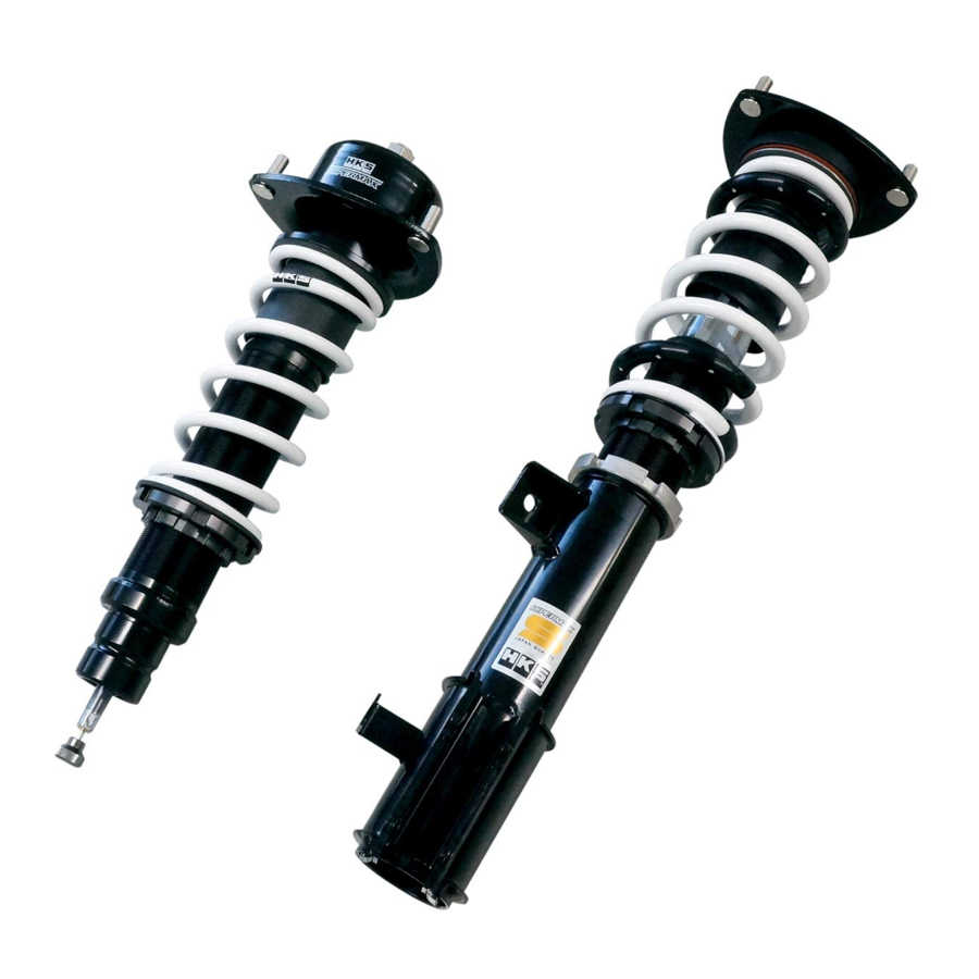
Suspension Components

| |
|
Removing the Factory Front Suspensions
| |
| When installing this product, do not use scissor-jacks supplied with the vehicle. Use of unstable scissor-jacks can lead to severe bodily injury or death. Always use vehicle lifts/hoists or garage jacks with jack-stands. |
- Jack up the vehicle, and remove wheels.
- Remove the brake line installation bolt ①. (Diagram 1-1)

- Remove the following:
The bolt from the lower front suspension assy ②
The ABS sensor harness ③
The stabilizer link nut ④.
(Diagram 1-2)

- Remove the nuts from the upper front suspension assy ⑤. (Diagram 1-3)

- Remove the factory front suspension assy from the vehicle.


 NOTICE NOTICE |
| When removing the factory front suspension assy, make sure not to pull on the brake line and ABS sensor. When these are pulled, it may damage the brakes. |
Installing the Front Suspensions
| NOTICE |
| Refer to the service manual for torque specs when tightening bolts and nuts. Make sure to tighten the bolts and/or nuts to the specified torque to avoid the damage to the bolts, nuts and/or shock absorber internals. |
- Install the provided front suspension assy to the vehicle using the upper front suspension assy installation nuts ⑤. (Torque Specs: 44Nm)
(Diagram 2-1)

*If you want to adjust vehicle height lower than default refer to diagram 5-1 - Install the following: The bolt for the lower front suspension assy
![]()
(Torque Specs: 54Nm) The ABS sensor harness ③
The stabilizer link nut ④.
(Torque Specs: 79Nm)
(Diagram 2-2)

- Install the brake line installation bolt ①.
(Torque Specs: 22Nm)
(Diagram 2-3)

- Mount the wheels back on, then lower the vehicle.


| |
| After re-mounting the tires, make sure the product does not come into contact with the wheels/tires. Re-alignment is required after installation of this product. |
Removing the Factory Rear Suspensions
|
| When installing this product, do not use scissor-jacks supplied with the vehicle. Use of unstable scissor-jacks can lead to severe bodily injury or death. Always use vehicle lifts/hoists or garage jacks with jack-stands. |
- Jack up the vehicle, and remove wheels.

- Remove the following: The stabilizer link nut ① The ABS sensor harness ②. (Diagram 3-1)
- Remove the following: The brake line installation bolt ③ The bolts and nuts from the lower rear suspension assy ④. (Diagram 3-2)

- Remove the nuts from the upper rear suspension assy ⑤. (Diagram 3-3)

- Remove the factory rear suspension assy from the vehicle.


| NOTICE |
| When removing the factory rear suspension assy, make sure not to pull on the brake line and ABS sensor. When these are pulled, it may damage the brakes. |
Installing the Rear Suspensions
| NOTICE |
| Refer to the service manual for torque specs when tightening bolts and nuts. Make sure to tighten the bolts and/or nuts to the specified torque to avoid the damage to the bolts, nuts and/or shock absorber internals. |
- Install the provided rear suspension assy to the vehicle using the upper rear suspension assy installation nuts ⑤. (Torque Specs: 49Nm) (Diagram 4-1)

- Install the following: The bolts and nuts for the lower rear suspension assy ④ (Torque Specs: 64Nm) The brake line installation bolt ③. (Torque Specs: 22Nm) (Diagram 4-2)

- Install the following: The ABS sensor harness ② The stabilizer link nut ①. (Torque Specs: 44Nm) (Diagram 4-3)

- Mount the wheels back on, then lower the vehicle.


| |
| After re-mounting the tires, make sure the product does not come into contact with the wheels/tires. Re-alignment is required after installation of this product. |
Adjusting the Damping
Damping adjustment and range
- The standard strut type
- For a suspension that a dial is attached on the top of each shock absorber, use the dial for adjustment.
- For a suspension that has a hole on top of the shaft, insert the provided adjustment dial to the hole to adjust the damping force.
- The MacPherson strut type
- Use the dial attached to the bottom of the suspension for adjustment.
- The side adjusting strut type
- Use the dial attached to the side of the suspension's lower part.
| Softest Setting | Initial Setting | Stiffest Setting * | |
| HIPERMAX S | 30 clicks back from the stiffest setting | 15 clicks back from the stiffest setting | Lightly turn the dial fully clockwise; then, turn it back counterclockwise until the first click. The suspension is now set at the stiffest point. |
* Stiffest is the 0 click position
- The adjustment dial has 30 steps. Lightly turn the dial full to clockwise; then, slightly turn it back to counterclockwise. The point where it clicks first is the stiffest point (0 click position). Over-tightening beyond the torque required for click adjustment can cause damage to the internal parts making damping adjustment impossible.
- Do not over-turn the dial; depending on the product, the dial may be turned counterclockwise more than 30 steps. Over-turning may cause damage to the internal parts.
- The dial positions of the right and left sides must be the same. If neglected, it may cause handling problems.

Adjusting the Ride Height
HKS has preset the ride height prior to shipment.
| JW5 Vehicle Height Data (inch) | FRONT | REAR | ||||||
| When Shipped | During Testing | Upper Limit | Lower Limit | When Shipped | During Testing | Upper Limit | Lower Limit | |
| Height | 22.8 | 22.6 | 23.5 | 22.0 | 23.9 | 23.8 | 24.8 | 22.8 |
| Height From Factory | -0.7 | -0.9 | 0.0 | -1.5 | -0.8 | -1.0 | 0.0 | -2.0 |
| Shock Body Length | 8.1 | ← | ← | ← | 14.4 | 14.2 | 15.0 | 13.4 |
| Spring Length | 7.4 | ← | 6.7 | 8.0 | 8.6 | ← | 8.4 | 8.7 |
| Thread Length | 1.3 | ← | 2.0 | 0.7 | 1.0 | 0.9 | 1.8 | 0.0 |
| Overall length | 11.7 (With 4 mm collar) | 11.5 (Without 4 mm collar) | 11.7 (With 4 mm collar) | 11.5 (Without 4 mm collar) | - | - | - | - |
| JW5 Vehicle Height Data (mm) | FRONT | REAR | ||||||
| When Shipped | During Testing | Upper Limit | Lower Limit | When Shipped | During Testing | Upper Limit | Lower Limit | |
| Height | 579 | 575 | 598 | 559 | 608 | 604 | 629 | 579 |
| Height From Factory | -19 | -23 | 0 | -39 | -21 | -25 | 0 | -50 |
| Shock Body Length | 205 | ← | ← | ← | 365 | 361 | 380 | 341 |
| Spring Length | 188 | ← | 170 | 203 | 218 | ← | 214 | 220 |
| Thread Length | 32 | ← | 50 | 17 | 26 | 22 | 45 | 0 |
| Overall length | 296 (With 4 mm collar) | 292 (Without 4 mm collar) | 296 (With 4 mm collar) | 292 (Without 4 mm collar) | - | - | - | - |
- The front shock body length is not adjustable. However, attaching/removing a (short) 4 mm spherical collar allows to adjust overall length. (Diagram 5-1) (Only for MAX S, MAX IV GT 20 SPEC.)


| |
| *Do not remove 10 mm spherical collar. Doing so will make parts contacted and cause damage. |
There is a limit to shock body length adjustment. Adjust between minimum and maximum figures as shown in the table above. Using the vehicle with the suspension outside the limit of minimum or maximum shock body length may cause damage to the suspension. Further, check for any contact between the suspension arms, wheels, etc. Driving while these parts are coming into contact may cause damage to the suspension and/or the vehicle.
Thread Length Adjustment/Vehicle Height Change
Height to be lowered ÷ Leverage Ratio = Amount of Thread Length Adjustment
Example: If the vehicle height of JW5 is intended to lower by 10mm:
10mm ( Height to be lowered ) ÷ 1.06 ( Leverage Ratio ) = 9.43...mm
Therefore, adjust the thread length by approximately 9mm.
Leverage Ratio: A ratio of the vehicle' height to the ride height adjuster's adjustment amount.
(JW5 – Front 1.06 / Rear 1.10)
Adjusting the Ride Height
- When the desired height is obtained, securely tighten the Bracket and Locking Bracket or Ride Height Adjuster and Locking Spring using the provided Spanner Wrench (12.7sq Slotted).
- Using a 12.7sq torque wrench, tighten as shown in the Diagram 6-1.


Front
[Spring Length (Preload) Adjustment]
- Loosen the Ride Height Adjuster and the Locking Spring.
- Turn the Ride Height Adjuster to set height.
- When the desired height is obtained, securely tighten the Locking Spring against the Ride Height Adjuster using 2 Spanner Wrenches to specified torque specs 50Nm.

*Thread length is the length between the bottom of the Locking Spring to the bottom of the cylinder screw.

Rear
[Shock Body Length Adjustment]
- Loosen the Bracket and the Locking Bracket.
- To set height, turn the Locking Spring to lengthen Shock Body Length, and turn the Ride Height Adjuster to shorten Shock Body Length.
- When the desired height is obtained, securely tighten the Bracket and Locking Bracket using the provided Spanner Wrenches to specified torque specs 100Nm.
[Spring Length (Preload) Adjustment]
- Loosen the Ride Height Adjuster and the Locking Spring.
- Turn the Ride Height Adjuster to set height.
- When the desired height is obtained, securely tighten the Locking Spring against the Ride Height Adjuster using 2 Spanner Wrenches to specified torque specs 50Nm.


Development Vehicle Data
Data from the test vehicle during development of this product is as follows. Please note that there may be small fluctuations between each car.
| HONDA S660 (JW5) Spec: S07A | |||
| Category | FRONT | REAR | |
| Vehicle Weight (Catalog) | 838 (838) lbs | 972 (992) lbs | |
| Leverage Ratio | 1.06 | 1.10 | |
| Tire Size (Air Pressure) | 165 / 55 - 15 ( 28 PSI ) | 195 / 45 - 16 ( 29 PSI ) | |
| Wheel Size | 5.0 JJ × 15 inset 45 | 6.5 JJ × 16 inset 40 | |
| Default Spring | Straight Type 7.9 ( 200 ) inches (mm) | Straight Barrel Type 8.7 ( 220 ) inches (mm) | |
| Spring Rate | 168 ( 3 ) lbs/inch (kgf/mm) | 224 ( 4 ) lbs/inch (kgf/mm) | |
| Damping Force ex/comp (@ 0.1m/s) | 221 / 127 N | 211 / 235 N | |
| Fuel Level | FULL | ||
| Alignment (Toe/Camber) | During Test | out 1.5 mm / -1° 06' | in 1.7 mm / -1° 00' |
| Standard Value | in 0 ± 1.5 mm / -0° 30' ± 30' | in 2 ± 1.2mm / -1° 30' ± 30' | |
Documents / ResourcesDownload manual
Here you can download full pdf version of manual, it may contain additional safety instructions, warranty information, FCC rules, etc.
Advertisement


Need help?
Do you have a question about the HIPERMAX S and is the answer not in the manual?
Questions and answers