
Related Manuals for HKS INTERCOOLER KIT


Summary of Contents for HKS INTERCOOLER KIT
- Page 9 REMARKS upgrades and ECU resetting are required. Install this intercooler kit only to the vehicle HKS BOLT ON TURBO KIT is installed. NOTICE This manual assumes that you have and know how to use the tools and equipment necessary to safely perform service operations on your vehicle.
-
Page 10: Parts List
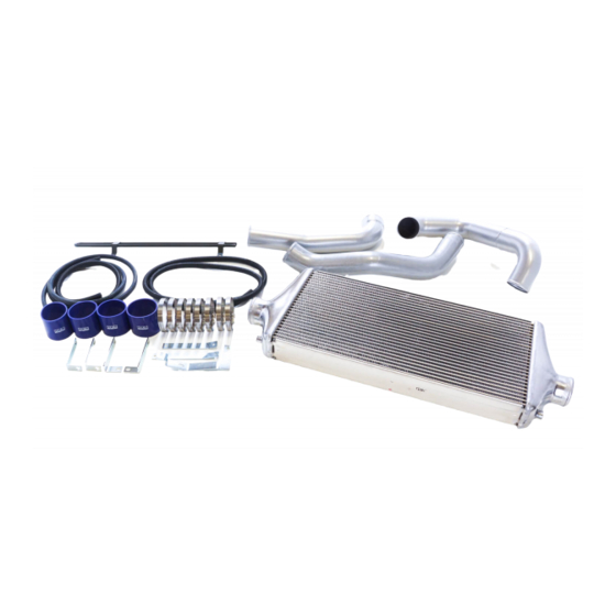
PARTS LIST PART NUMBER DESCRIPTION IMAGE REMARKS 1 G17910-S42010-00 INTERCOOLER CORE Assy 1 G17951-S42010-00 INLET PIPE 1 G17971-S42010-00 OUTLET PIPE No.1 1 G17971-S42021-00 OUTLET PIPE No.2 1 G17981-S42010-00 OUTLET PIPE BRACKET INTERCOOLER BRACKET №1 2 G17921-S42010-00 INTERCOOLER BRACKET №2 1 G17921-S42020-00 UNIVERSAL BRACKET φ50 1... - Page 11 PARTS LIST PART NUMBER DESCRIPTION IMAGE REMARKS 7 FLAT WASHER M8 7 SPRING WASHER M8 5 FLANGE NUT M8 23 15719-037100 SPONGE SHEET 24 G09912-K00020-00 C-RING 25 91731-065100 O-RING 26 G09933-F43020-00 PLUG PLATE INSTRUCTION MANUAL 28 E04251-S42012-00 INSTALLATION MANUAL...
- Page 12 Remove the front bumper. Remove the reinforcement and the plastic parts of the upper reinforcement. (D1-1) Remove the horn and the outside temperature sensor. Remove the plastic parts of the radiator side and the front Installation of the Intercooler Kit...
- Page 13 (1) Install intercooler bracket No.2 to the bottom of the reinforcement using the following supplied parts: (D2-1, D2-2) Intercooler Bracket No.2 (P7 x 1) Bolt M8 L=15 (P19 x 1) Flat Washer M8 (P20 x 1) Spring Washer M8 (P21 x 1) ...
- Page 14 Make sure the intercooler core assembly does not come in contact with other parts. Adjust the position if necessary. (4) Install the chamber pipe No.1 included in HKS BOLT ON TURBO KIT as shown in the diagram 2-6. (5) Install the inlet pipe to the intercooler core assembly and the chamber pipe No.1 installed in...
- Page 15 (6) Install outlet pipe No.1 to the intercooler core assembly and the body using the following supplied parts: (D2-8, D2-9) Outlet Pipe No.1 (P3×1) Outlet Pipe Bracket (P5×1) Universal Bracket φ50 (P8×1) Insulator Rubber (P10×1) Hose Clamp #28 (P11×3) ...
- Page 16 ・ After installing the intercooler kit, boost pressure tends to be reduced. Therefore, it is recommended to use HKS EVC or adjust the actuator to maintain the boost pressure. After installation, make sure the boost pressure is maintained at less than 0.40㎏/c㎡.
- Page 17 Confirmation After Installation Check the following after the installation process is complete. (1)Check the following before starting the engine: Make sure pipes and hoses are routed and connected correctly. Make sure hose clamps are tightened. Make sure the negative cable terminal is securely attached to the battery. ...
Need help?
Do you have a question about the INTERCOOLER KIT and is the answer not in the manual?
Questions and answers