Advertisement
Quick Links
INSTRUCTION MANUAL
Application: UNIVERSAL KIT
1. INTRODUCTION
Thank you for your purchase of Power Editor.
・ This manual indicates items that require attention in order to install this product
safely and lists precautions to avoid any possible damage and/or accidents.
・ This product was designed based on installation onto a specific factory vehicle
or a vehicle using other HKS products. The performance and/or safety cannot be
guaranteed if this product was installed onto other inapplicable vehicles.
・ Contact HKS dealer for any lost parts, replacement, and this manual.
・ HKS will not be responsible for any damage caused by incorrect installation and/or
use of this product.
・ This product works only with a vehicle with DC12V negative ground.
・ The specifications of this product are subject to be changed without notice.
・ This manual is subject to be revised without notice.
Product
Power Editor
Code Number
42999-AK 017
Use
Boost up of turbocharged vehicle
Application
UNIVERSAL KIT
2. Safety Precaution
The following precautions for use of this product are to prevent possible
accidents and/or injuries and for proper use.
Indicates risk of serious injury and/or possible death.
WARNING :
Indicates risk of serious injury or property damage.
CAUTION :
● Make sure to work on the vehicle in a well-ventilated area to prevent possible
explosion or a fire.
● Make sure to hold connectors when removing them to avoid possible damage to
other electronics parts and/or a fire caused by disconnection or a short circuit.
● Stop using the product if any unusual situation is noticed. Consult the dealer
immediately. Failure to do so may cause an electric shock, burn out, or damage
to the vehicle.
● Make sure to work on the vehicle in area where a vehicle can be parked safely.
● Do not install this product by yourself.
● Do not modify, disassemble, and/or remodel the product and attached parts to
avoid any damage to the unit and/or harness.
● To avoid possible malfunction and damage to the engine, install the unit away
from excessive heat or water/moisture.
● Make sure all connections and wiring are not disconnected, short circuited,
or incorrect. If so, it may cause an electric shock, burn out, or damage to the
vehicle.
● If any unusual noise, scents, and/or vibrations are noticed, consult the dealer
immediately.
● If any unusual noises, scents, and/or vibrations are noticed while driving, please
refer to a factory repair manual.
● Confirm the following before reading the ECU data with this product:
・ The ECU is a factory standard.
・ Data on the ECU is not modified.
● When disconnecting, always hold the connector part, pulling the cables
may break connection.
● Before an automobile inspection and/or repair,It is necessary to remove this
product.
● Daily maintenance on the vehicle is the responsibility of the owner.
INSTRUCTION
E05253-K00030-00
April. 2018
Ver. 3-1.01
WARNING
CAUTION
ー 1 ー
3. Product Features
・ By connecting this product between Pressure sensor and ECU, boost can be
easily raised.
・ This product is valid only for vehicles equipped with ECUs that boost control
depending on ECU learning value.
・ Even after installing this product, you can return to the normal state by
connecting the "return connector" instead of the Power Editor main unit.
・ You can edit the boost-up data by connecting to the personal computer with
USB harness included in the product and using Easy Writer for Power Editor.
・ Because there is no boost-up data in the main unit, you need to create data
with Power Editor Easy Writer.
・ Easy Write for Power Editor may be downloaded from HKS homepage.
4. Parts List
1
Power Editor
2
Connection harness
1pc.
1pc.
6
Tie wrap (small)
7
Tie wrap (large)
4pc.
2pc.
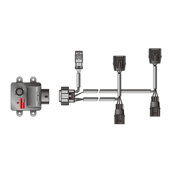
5. Diagrammatic illustration
1. Stop the engine of the vehicle and disconnect the cable terminal from the
negative terminal of the battery.
2. Install the Power Editor main unit in an arbitrary place.
・ Avoid the following places.
- Places where the temperature becomes high like the engine body.
- Places where product may directly come in contact with water.
・ Confirm that the connection harness reaches the pressure sensor.
・ Use double side tape and tie wraps to attach.
Attaching with double-sided tape only is dangerous as it my peel off due
to age deterioration.
3. Connect the Power Editor main unit and Connector for main unit.
Power Editor main unit
Connector for main unit
Connection harness
(Sensor Output1)
Blue
(Sensor 5V)
Red
(Sensor GND)
Black
ECU
(Sensor Output2)
Green
*If only one pressure sensor is used, please use only pressure sensor 1 wiring.
4. Lock the connection harness of Power Editor with tie wrap so as not to hinder
the running of the vehicle.
・ Avoid places where the temperature becomes high, such as the engine body.
5. After confirming that all connectors are correctly connected, connect the cable
terminal to the negative terminal of the battery.
6. Turn the ignition on and check that the LED of the Power Editor main unit lights up.
・ If the ignition is turned on but the Status LED does not light up, the reason might
be poor connection.
3
USB harness
4
Recovery Connector
1pc.
1pc.
8
Double-sided tape
9
Wire splice
10
2pc.
10pc.
Status LED
Light Off: Power Off
Light On: Power On
One Blink: Channel 1 Data Error
Two Blinks: Channel 2 Data Error
Three Blinks: Channel 1/ Channel 2
Data Error
When the LED flashes the boost
will not rise, it will behave like a
normal vehicle.
USB Connector Harness
・ Use tie wraps to fixate connector to prevent
it from touching any other parts when driving.
White
(Sensor Input1)
Red
(Sensor 5V)
Black
(Sensor GND)
Orange (Sensor Input2)
ー 2 ー
5
Heat Shrink Insulation Tube
8pc.
取扱説明書
E89671-T41010-00
2018.01発行
Ver. 3-1.01
Instruction Manual
1pc.
Pressure
sensor1
Pressure
sensor2
Advertisement

Related Manuals for HKS Power Editor


Summary of Contents for HKS Power Editor
- Page 1 6. Turn the ignition on and check that the LED of the Power Editor main unit lights up. ・ If the ignition is turned on but the Status LED does not light up, the reason might be poor connection.
- Page 2 7. Terminal layout 7. Please attach the connection harness referring to the installation method example of the general purpose Power Editor on HKS homepage. Power Editor main unit V I E W Color Description Power (SENSOR_5V) white SENSOR_IN1 orange SENSOR_IN2...
Need help?
Do you have a question about the Power Editor and is the answer not in the manual?
Questions and answers