Hytorc MXT+ Series, MXTP-01, MXTP-03, MXTP-05, MXTP-10 Manual
- Basic operation manual (24 pages)
- Also fits for
- Mxt plus series
- Mxtp-01
- Mxtp-03
- Mxtp-05
- Mxtp-10
Advertisement
-
1
GENERAL SAFETY INFORMATION
- 1.1 GENERAL
- 1.2 GENERAL SAFETY RULES
- 1.3 PROJECTILE HAZARD
- 1.4 ENTANGLEMENT HAZARDS
- 1.5 OPERATING HAZARDS
- 1.6 REPETITIVE MOTIONS HAZARDS
- 1.7 ACCESSORY HAZARD
- 1.8 WORKPLACE HAZARDS
- 1.9 DUST AND FUME HAZARDS
- 1.10 NOISE HAZARDS
- 1.11 VIBRATION HAZARDS
- 1.12 ADDITIONAL SAFETY INSTRUCTIONS FOR HYDRAULIC POWER TOOLS
- 1.13 GENERAL OPERATOR GUIDELINES
- 1.14 PERSONAL PROTECTIVE EQUIPMENT (PPE)
- 2 TOOL DESCRIPTION
- 3 PREPARATION AND SETUP
-
4
BOLTING WITH SOCKET AND REACTION ARM
- 4.1 INSTALLING REACTION ARM (DRIVE SPLINE)
- 4.2 INSTALL SOCKET
- 4.3 INSTALLING REACTION ARM (REAR SPLINE)
- 4.4 CONNECT HYDRAULIC HOSES
- 4.5 QUICK-CONNECT COUPLERS (PUSH-PULL)
- 4.6 INITIALIZE PUMP AND CHECK PRESSURE
- 4.7 DETERMINE PRESSURE REQUIREMENTS
- 4.8 SAMPLE TORQUE CHART
- 4.9 INSTALL HANDLE
- 4.10 MOUNT TOOL ONTO THE APPLICATION
- 4.11 CONVENTIONAL TORQUE TIGHTENING
- 4.12 CONVENTIONAL TORQUE LOOSENING
- 4.13 RELEASING A LOCKED-ON TOOL
- 5 BOLTING WITH THE HYTORC WASHER
- 6 BOLTING WITH THE HYTORC NUT
- 7 CARE AND MAINTENANCE
- 8 WARRANTY
- 9 Documents / Resources
GENERAL SAFETY INFORMATION

Read all safety warnings designated by the  symbol and all instructions.
Read all instructions before use. To reduce the risk of injury user must read manual.
GENERAL
- Employer Responsibility: The user's employer shall assess the specific risks that can be present as a result of each use.
- Maintenance Instructions: General maintenance recommendations include care and handling instructions (see CARE AND MAINTENANCE Section).
- Special Markings on the Tool: There are no special markings or symbols on the tool.
- Residual Risks: When this tool is used for its intended purpose by trained individuals equipped with adequate personal protective equipment according to the instructions in this document, there are no known residual risks.
- Statement of Use: The MXT+ Hydraulic Torque Tool is intended for use in tightening fasteners with controlled torque in heavy duty industrial bolting applications.
- Trained User Only: This tool should be used only by fully trained personnel, and this document is written only for trained professionals. This tool should not be used without proper training and supervision. Contact HYTORC for additional training information.
GENERAL SAFETY RULES
- Maintenance must be performed by a qualified HYTORC technician.
- Operating the tool in any fashion other than as described herein can result in serious bodily injury and is forbidden.
- For multiple hazards, read and understand the safety instructions before installing, operating, repairing, maintaining, changing accessories on, or working near the tool. Failure to do so can result in serious bodily injury.
- Only qualified and trained operators should install, adjust or use the tool.
- Do not modify this tool. Modification of the tool invalidates the warranty and can reduce the effectiveness of safety measures and increase the risks to the operator.
- Do not discard the safety instructions; give them to the operator.
- Do not use the tool if it has been damaged.
- Tools shall be inspected periodically to verify that the ratings and markings are legibly marked on the tool. The employer/user shall contact the manufacturer to obtain replacement marking labels when necessary.
PROJECTILE HAZARD
- Failure of the workpiece, of accessories or even of the inserted tool itself can generate high-velocity projectiles.
- Always wear impact-resistant eye protection during operation of the tool. The grade of protection required should be assessed for each use.
- Ensure that the workpiece is securely fixed.
ENTANGLEMENT HAZARDS
- Entanglement hazards can result in choking, scalping and/or lacerations if loose clothing, personal jewelry, neckwear, hair or gloves are not kept away from the tool and accessories.
- Gloves can become entangled with the rotating drive, causing severed or broken fingers.
- Rotating drive sockets and drive extensions can easily entangle rubber-coated or metal-reinforced gloves.
- Do not wear loose-fitting gloves or gloves with cut or frayed fingers.
- Never hold the drive, socket or drive extension while operating tool.
- Keep hands away from rotating drives.
OPERATING HAZARDS
- The use of the tool can expose the operator's hands to hazards including crushing, impacts, cuts and abrasions and heat. Wear suitable gloves to protect hands.
- Operators and maintenance personnel must be physically able to handle the bulk, weight and power of the tool.
- Hold the tool correctly; be ready to counteract normal or sudden movements and have both hands available.
- Maintain a balanced body position and secure footing.
- In cases where the means to absorb the reaction torque are requested, it is recommended to use a suspension arm whenever possible. If that is not possible, side handles are recommended for straightcase and pistol-grip tools. Reaction bars are recommended for angle nutrunners. In any case, it is recommended to use a means to absorb the reaction torque above 4 N·m for straight tools, above 10 N·m for pistol-grip tools, and above 60 N·m for angle nutrunners.
- Release the start-and-stop device in case of an interruption of the energy supply.
- Use only lubricants recommended by the manufacturer.
- Beware of crushing hands between tool and workpiece, especially when unscrewing.
REPETITIVE MOTIONS HAZARDS
- When using tool the operator can experience discomfort in hands, arms, shoulders, neck, or other parts of the body.
- The operator should adopt a comfortable posture while maintaining secure footing and avoiding awkward or off balanced postures. The operator should change posture during extended tasks to help avoid discomfort and fatigue.
- If the operator experiences symptoms such as persistent or recurring discomfort, pain, throbbing, aching, tingling, numbness, burning sensations or stiffness, these warning signs should not be ignored. The operator should tell the employer and consult a qualified health professional.
ACCESSORY HAZARD
- Disconnect tool from the energy supply before changing the inserted tool or accessory.
- Do no touch sockets or reaction arms during use, as this can cause serious injury.
- Use only sizes and types of accessories that are recommended by the tool manufacturer.
- Use only impact grade sockets in good condition, as sockets in poor condition can shatter and become a projectile.
WORKPLACE HAZARDS
- Slips, trips and falls are major causes of workplace injury. Be aware of slippery surfaces caused by the use of the tool and also of trip hazards caused by the air line or hydraulic hose.
- Proceed with care in unfamiliar surroundings. Hidden hazards, such as electricity or other utility lines, can exist.
- The tool is not intended for use in potentially explosive atmospheres and is not insulated against electric power.
- Make sure there are no electrical cables, gas pipes, etc., that can cause a hazard if damaged by use of the tool.
DUST AND FUME HAZARDS
- Where dust or fumes are present in the environment where this tool is used, follow instructions as required by the employer and occupational health and safety regulations to provide respiratory protection for tool users.
- Dust and fumes generated when using power tools can cause ill health (for example cancer, birth defects, asthma and/or dermatitis); risk assessment and implementation of appropriate controls for these hazards are essential.
NOISE HAZARDS
- Exposure to high noise levels can cause permanent, disabling hearing loss and other problems, such as tinnitus (ringing, buzzing, whistling or humming in the ears). Therefore a risk assessment and implementation of appropriate controls for these hazards are essential.
- Appropriate controls to reduce risk may include damping materials to prevent workpieces from "ringing".
- Use hearing protection in accordance with instructions and as required by health and safety regulations.
- Operate and maintain the tool as recommended in instructions, to prevent increase in noise levels.
- If the tool has a silencer, always ensure it is in place and in good working order when operating.
- Select, maintain and replace tool as required to prevent an unnecessary increase in noise.
VIBRATION HAZARDS
- Exposure to vibration can cause disabling damage to the nerves and blood supply of the hands and arms.
- Keep hands away from the nutrunner sockets.
- If you experience numbness, tingling, pain or whitening of the skin in your fingers or hands, stop using the tool, tell your employer and consult a physician.
- Operate and maintain the tool as recommended, to prevent unnecessary increase in vibration levels.
- Do not use worn or ill-fitting sockets or extensions, as this is likely to cause a substantial increase in vibration.
- Select, maintain and replace tool as required to prevent an unnecessary increase in vibration levels.
- Sleeve fittings should be used where practicable.
- Hold the tool lightly but securely; the risk from vibration is generally greater with a tighter grip.
ADDITIONAL SAFETY INSTRUCTIONS FOR HYDRAULIC POWER TOOLS
- Do not exceed the maximum relief-valve setting stated on the tool.
- Carry out a daily check for damaged or worn hoses or hydraulic connections and replace if necessary.
- Use only clean oil and filling equipment.
- Power units require a free flow of air for cooling purposes and should, therefore, be positioned in a wellventilated area free from hazardous fumes.
- Ensure that couplings are clean and correctly engaged before operation.
- Do not inspect or clean the tool while the hydraulic power source is connected. Accidental engagement of the tool can cause serious injury.
- Do not install or remove the tool while the hydraulic power source is connected. Accidental engagement of the tool can cause serious injury.
- Be sure all hose connections are tight.
- Wipe all couplers clean before connecting. Failure to do so can result in damage to the quick couplers and cause overheating.
PUMP UNITS
- Only use HYTORC pump units. Do not modify the pump unit in any way.
- Do not use electric pumps in potentially volatile atmospheres. If in doubt, use a pneumatic pump unit. Metal-onmetal contact can cause sparks. Take appropriate additional measures.
- Make sure that maximum operating pump pressure is under 10,000 PSI (700 bar).
- Make sure that the pump unit is properly grounded.
- Make sure pump is filled with HYTORC 32 AW hydraulic oil. Check local conditions to be sure hydraulic oil has the correct ISO viscosity rating for your local climate. Do not mix different grades of oil.
- Make sure that the oil level is between MIN and MAX indicator. Use the oil level sight glasses to check level.
- Make sure that the oil filler cap is secure.
HYDRAULIC HOSES
- Only use HYTORC hydraulic hoses. Do not modify hoses in any way.
- Make sure that all hoses are securely connected and are not kinked or twisted.
- Keep all hoses away from reaction points.
- Replace any damaged hoses immediately. Replace all hoses at least every three years.
REACTION ARMS
- Only use HYTORC reaction arms. Do not modify reaction arms in any way.
- Place reaction arm against a solid reaction point that can handle the load.
- Make sure that at least 0.5" (12 mm) of reaction arm contacts the reaction point.
- Make sure that the reaction arm is locked onto the spline of the tool.
- Do not place the reaction arm against a round or inclined reaction point.
- Do not place any part of your body between the reaction arm and the reaction point.


SOCKETS
- Always use premium impact grade sockets.
- Always use the strongest socket for the job.
- Always react the wrench in-line with the nut.
- Always take special care with extensions and adapters.
- Always pin the socket to the drive.
- Never use a cut-down or modified socket.
- Never strike a socket under load.
- Always avoid the danger zones.
- Always inspect every socket before use.
- Always make sure the socket's width across flats (AF) matches that of the nut or bolt.
- Do not use common extension pieces or step-up/step-down adapters. HYTORC can develop customized accessories to ensure safe operation. Contact your local HYTORC representative for information.
- Do not use chrome-plated sockets, sockets that have been excessively heated or cooled or sockets that are deformed or brittle from use.
GENERAL OPERATOR GUIDELINES
- Only qualified personnel who have thoroughly read this document may operate this tool. Failure to safely operate this tool may result in serious injury or death.
PERSONAL PROTECTIVE EQUIPMENT (PPE)
• Always wear appropriate protective equipment including gloves, impact-resistant eye protection, hearing protection, hard hat and safety shoes when operating tool. Check local conditions for each use.
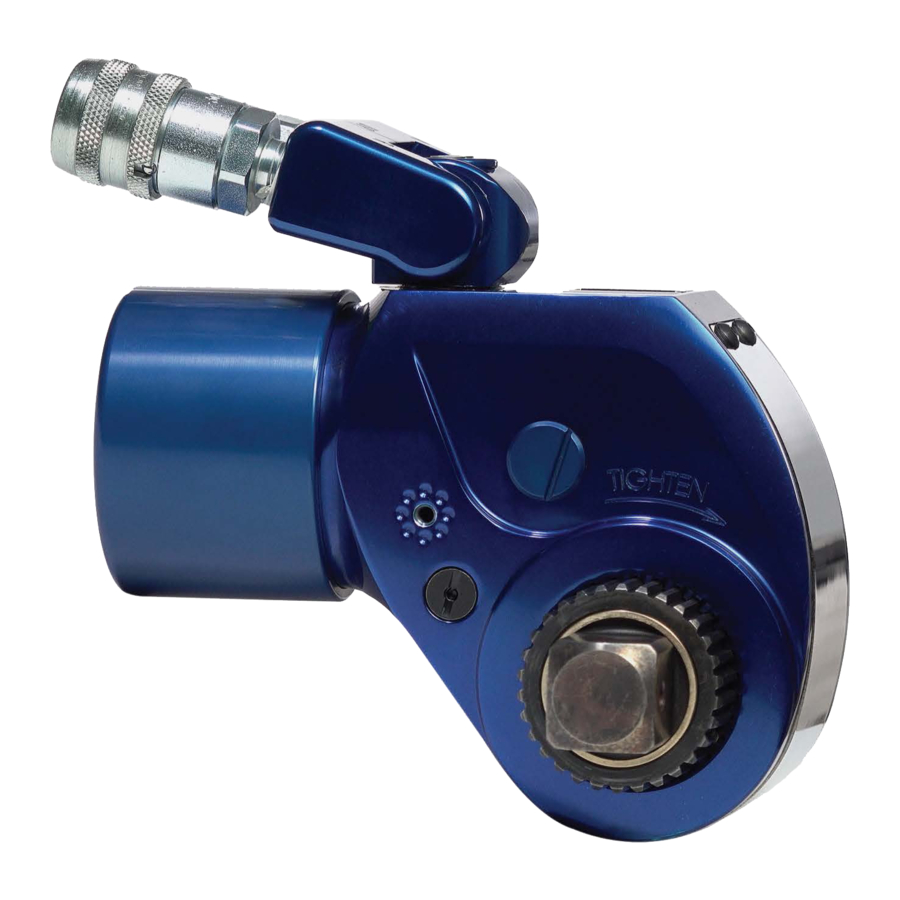
TOOL DESCRIPTION

The MXT+ Hydraulic Torque Wrench combines the best features from the original MXT tool with the latest advanced technology including coaxial reaction drive, auto-release feature and a new cycle counter.
- Constructed from higher strength materials for rugged industrial use and highly repeatable performance.
- The coaxial drive combined with rear reaction feature provide flexibility to configure the tool in the field, essentially replacing the need for two separate tools with one single tool.
- The MXT+ Wrench is compatible with standard sockets as well as the HYTORC Washer and HYTORC Nut for safe, simple and precise mechanical tensioning.
- An integrated auto-release feature and new quick-couplers provide faster job setup and completion.
- The new cycle counter helps keep the tool in calibration, allowing users to schedule preventative maintenance for peak performance and longer tool life.
- Dual Reaction: The tool accommodates both rear-attaching and concentric reaction fixtures.
- Reversible Square Drive: Allows rapid change between tighten and loosen modes.
- Uniswivel 180°/360° adjustable coupler provides maximal freedom in arranging tools and hoses.
- Concentric Reaction Spline: Decreases side-load and provides more uniform application of torque.
- System accuracy of the tool when used with a HYTORC power pack is +/- 3%.
- Using a calibrated gauge will enhance the accuracy of your HYTORC System.
The MXT+ Hydraulic Torque Tool has an extensive range of reaction arms available for various bolting assemblies and configurations. The image below shows the most common types of reaction arms which vary in both length and size.
Please contact your local HYTORC representative for all available options.

LEGEND (CLOCKWISE FROM TOP LEFT)
- Crab Nut Fixtures
- WTCT Reaction Fixture
- Rotatable Reaction Arm
- ALCO Arm
- Rear Reaction Arm Assembly
- Offset Reaction Sleeve
- Reaction Sleeve
- Hex Drive
- HYTORC Nut Drive Assembly
- HYTORC Washer Driver
- Reaction Arm Casted (Short)
- Track Pad Fixture
PREPARATION AND SETUP
INSPECT TOOL
- Check the calibration sticker to verify the most recent calibration date.
- Inspect cycle counter to ensure lens is fully seated and not cracked.
- Monitor cycle count to aid in scheduling calibration and preventative maintenance.
- Remove and inspect the square drive and ensure there is no damage to the inner or outer splines.
- Inspect the uniswivel and couplers for signs of damage or oil leaks. Leaking tools should not be used.
DETERMINE REQUIRED DIRECTION OF ROTATION

For tightening, the square drive must be inserted so that "TIGHTEN" is visible when mounted on the application.

For loosening, the square drive must be inserted on the opposite side so that "LOOSEN" is visible when mounted.
CHANGING THE DIRECTION OF ROTATION
- Push button on drive retainer and pull the square drive to remove it from the tool.
- Remove the drive retainer and reinsert it on the opposite side of the tool.
- Insert square drive into opposite side of the tool while pushing button on the drive retainer.
- Release the button on the drive retainer after square drive clicks into place. Challenge drive to make sure it is secure.


BOLTING WITH SOCKET AND REACTION ARM
The tool is configured for conventional bolting by installing a socket and either a drive spline reaction arm or a rear spline reaction arm.

Do not place any part of your body between reaction arm and reaction point to avoid injury. Never modify a reaction arm! Changes in reaction arm may lead to personal injury or damage tool.
INSTALLING REACTION ARM (DRIVE SPLINE)
- Slide reaction arm over drive spline while aligning the Allen Set Screw with the flat on the Reaction Spline.
- Tighten Allen Set Screw to firmly attach the reaction arm to the spline.
- Challenge the reaction arm to make sure it is firmly secured onto the tool.
")
")
INSTALL SOCKET
NOTE: Make sure the rubber O-ring is installed on the socket before installation.
- Insert the retaining pin part-way into the socket as shown.
- Slide socket over square drive while aligning hole in the socket with hole in the square drive.
- Insert the retaining pin into the socket as shown.
- Push the pin through both socket and square drive until the pin is flush against the socket.
- Slide the O-ring over the pin to retain pin while operating the tool.


INSTALLING REACTION ARM (REAR SPLINE)
- Push the catch lever on the back of the reaction arm.
- Slide reaction arm over rear spline until seated.
- Release the catch lever.
- Challenge the reaction arm to make sure it is firmly secured onto the tool.
- Use rear spline cover to protect tool when not in use.
")
")
CONNECT HYDRAULIC HOSES
The tool and power pack are connected by a 10,000 PSI operating pressure (40,000 PSI burst) twin-line hose assembly. Each end of the hose has both a male and a female connector (the male coupler is inserted into the female).
NOTE: An odd number of hoses is required to extend the hydraulic hose length.
![]()
Make sure system is depressurized before connecting or disconnecting hoses.- Make sure that all hydraulic hoses are rated for 10,000 PSI Operating Pressure.
- Remove protective caps from couplings and inspect couplings for dirt and debris.
- Connect supply hose to male coupling "A". Connect return hose to female coupling "R"
- To avoid tool malfunction. do not reverse coupler orientation.
- If daisy chaining hoses, use an odd number of hoses to preserve coupler orientation.
- Protect pump couplings with caps and plugs when not in use, to avoid damage and contamination.


QUICK-CONNECT COUPLERS (PUSH-PULL)
To connect hoses with quick-connect couplers, insert male end into female end and push until it snaps in place. Twist locking ring so that ball (A) does NOT align with slot (B) to prevent accidental uncoupling. To disconnect, align ball (A) with slot (B) and pull back locking sleeve.
Always make sure system is depressurized before disconnecting hoses.
")
INITIALIZE PUMP AND CHECK PRESSURE
NOTE: Always follow pump manufacturer's guidelines and instructions.
- Ensure that all components and connections are compatible and have sufficient power.
- Check that voltage and frequency of main supply outlet match information on the pump plate.
- Power-on pump and check that pressure builds to 10,000 psi in advance, 1,500 psi in retract.
- Air Powered Pump (optional): Verify air supply is 100 psi and 130 CFM.
DETERMINE PRESSURE REQUIREMENTS
- Tool Torque output is calibrated over a range of hydraulic pressures. Select pressure necessary for desired torque from the table provided.
- Adjust pump regulator to set the desired torque output.
NOTE: Always adjust regulator pressure UP, not down.
SAMPLE TORQUE CHART

INSTALL HANDLE
- Installation and use of the tool handle ensures maximum safety when handling the tool.
- Simply thread the handle into the tool with the twist knob on top until firmly attached.
- Partially unscrew knob to rotate handle to desired position after the tool is mounted.


MOUNT TOOL ONTO THE APPLICATION
- Make sure tool is set up appropriately for TIGHTEN or LOOSEN with appropriate socket.
- Place the driver onto the socket, making sure socket is fully engaged.
- Position the reaction arm against an adjacent nut, flange or other solid reaction point.
![]()
Follow all safety instructions regarding reaction arms.
![warning]() NOTE: If using rear-spline reaction arm, adjust arm as necessary to align with reaction surface.
NOTE: If using rear-spline reaction arm, adjust arm as necessary to align with reaction surface. - Make sure that hose connections are clear of obstructions and out of harm's way.
- If needed, install back wrench or apply back wrench fixture.
- THEN, AND ONLY THEN, apply momentary pressure to the system to ensure proper tool placement. If it doesn't look or act right, STOP and re-adjust the reaction arm.


CONVENTIONAL TORQUE TIGHTENING
- Press and hold the advance button on the pump control until you hear a click – the piston is fully extended, and the square drive will no longer turn.
- Release advance button to retract piston until you hear a click to signify tool is reset.
- Continue push-advance-click-release cycle until tool stalls and nut no longer visibly turns.
![]()
Always attempt one final cycle to ensure that "stall" point has been reached.
CONVENTIONAL TORQUE LOOSENING
- Set pump to the maximum pressure (10,000 PSI, 700 bar).
- Reverse the square drive and mount tool onto nut or bolt with "LOOSEN" visible.
- Repeat the same push-advance-click-release cycle outlined above until you can loosen the nut by hand.
RELEASING A LOCKED-ON TOOL
- The MXT+ Tool has an automated release feature and does not require manual release.
- Continue advancing the pump until the tool loosens and frees itself from the application. Remove tool.
BOLTING WITH THE HYTORC WASHER
The HYTORC Washer System consists of the HYTORC Reaction Washer and Backup Washer. The tool is configured for bolting with the HYTORC Washer by installing a dual-socket HYTORC Washer Driver. The driver engages the lobes of the washer while constraining the reaction force of the tool as it tightens.
NOTE: No reaction arm is required when bolting with the HYTORC Washer. Installation of the spline cover is recommended.
INSTALLING THE HYTORC WASHER DRIVER
- Slide the appropriate size HYTORC Washer Driver over the square drive and spline while aligning the thumb screw with the flat on the spline.
- Tighten the thumb screw to secure driver. Challenge the Driver to make sure it is secure.


TIGHTENING THE HYTORC WASHER
- Connect hydraulic hoses and set pump to desired torque output.
- Place the tool onto the nut and HYTORC Washer, so that the driver is fully engaged.
- Push and hold the advance button on the pump remote until the tool fully advances, then release.
- Continue successive cycles of "PUSH-ADVANCE-CLICK-RELEASE" until the tool "stalls" at the pre-set Torque/PSI and the nut no longer turns.
LOOSENING THE HYTORC WASHER
- Configure the HYTORC Washer Driver so that LOOSEN is visible when tool is mounted on the application.
- Turn up the pump pressure or torque value to the maximum or peak value.
- Mount the driver onto the application so that it engages both the nut and the HYTORC Washer.
- Apply pressure until the out sleeve moves freely.
- Loosen bolts gradually in reverse order of tightening, to prevent misalignment.
- Remove the nut and HYTORC Washer by hand.


BOLTING WITH THE HYTORC NUT
The HYTORC Nut is a dual spline mechanical tensioning device that replaces regular hex nuts on an application. The tool is configured for bolting with the HYTORC Nut by installing the HYTORC Nut Driver.
NOTE: No reaction arm is required when bolting with the HYTORC Nut. Installation of the rear spline cover is recommended.
INSTALLING THE HYTORC NUT DRIVER
- Push button on drive retainer and remove square drive.
- Slide the HYTORC Nut Direct Drive into the tool housing. Insert the special drive retainer on the opposite side and twist clockwise to tighten.
- Place the tool onto the HYTORC Nut, making sure that the driver is fully engaged.


TIGHTENING THE HYTORC NUT
- Connect hydraulic hoses and set pump to desired torque output.
- Push and hold the advance button on the pump remote until the tool fully advances, then release.
- Continue successive cycles of "PUSH-ADVANCE-CLICK-RELEASE" until the outer sleeve no longer turns and the tool stalls at the specified pressure.
LOOSENING THE HYTORC NUT
- Configure the HYTORC Nut Direct Drive so that LOOSEN is visible when tool is mounted on the application.
- Turn up the pump pressure or torque value to the maximum or peak value.
- Engage the Driver and the HYTORC Nut.
- Apply pressure until the out sleeve moves freely.
- Loosen gradually in reverse order of tightening, to prevent misalignment.
- Remove the HYTORC Nut by hand.


CARE AND MAINTENANCE
TOOL MAINTENANCE
- Maintenance must be performed by a qualified technician.
- Use rear spline cover to protect tool when not in use.
- Inspect the tool before each use. Repair or replace any obviously worn or damaged parts.
- Have the tool disassembled, cleaned, inspected and lubricated at least regularly. More frequent maintenance may be appropriate depending on local practice, usage and conditions.
- Modifying any of the components will invalidate the warranty.
CALIBRATION
- HYTORC recommends all tools be tested and recalibrated periodically. More frequent calibration may be appropriate depending on local practice, usage and conditions.
- Customer/user is responsible for arranging testing and recalibration.
- Contact 1-800-FOR-HYTORC for assistance or further information.
- When not in use store tool, components, instructions and calibration reports in plastic storage case.
WARRANTY
Two (2) years after the date of purchase.
If you have questions about the warranty, contact our customer service center at 201-828-5270.
Documents / ResourcesDownload manual
Here you can download full pdf version of manual, it may contain additional safety instructions, warranty information, FCC rules, etc.
Download Hytorc MXT+ Series, MXTP-01, MXTP-03, MXTP-05, MXTP-10 Manual
Advertisement


Need help?
Do you have a question about the MXT+ Series and is the answer not in the manual?
Questions and answers