Table of Contents
Advertisement
Quick Links
Advertisement
Table of Contents

Related Manuals for Hytorc jGun Series


Summary of Contents for Hytorc jGun Series
- Page 1 jGun pneumatic socket wrench Technical manual...
- Page 2 Details and values given in this manual are average values and have been compiled with care. Details and values are not binding. HYTORC disclaims any liability for damage or detriments suffered as a result of reliance on the information given...
-
Page 3: Table Of Contents
Contents Contents About the document.................6 Purpose of the document......................6 How to work with the document....................6 Languages........................... 6 Illustrations...........................6 Safety symbols in the document....................6 Related documents........................7 Revision history..........................7 Contact information........................7 Safety.......................8 General safety instructions......................8 2.1.1 Personnel.......................... 8 2.1.2 Work area..........................8 2.1.3 Equipment......................... - Page 4 Tightening and loosening a bolted flange connection..............35 7.5.1 Tightening a bolted flange connection................36 7.5.2 Loosening a bolted flange connection................36 Maintenance..................37 Preventive maintenance......................37 Maintenance by HYTORC......................37 Filling the oil filter reservoir......................37 Draining the water filter reservoir manually................37 Troubleshooting..................39 Technical data..................40 10.1...
- Page 5 Contents 10.2.1 jGun DSP-.5........................42 10.2.2 jGun DSP-1........................43 10.2.3 jGun DSP-2........................43 10.2.4 jGun DSP-3........................43 10.2.5 jGun DSP-5........................43 10.2.6 jGun DSP-8........................44 10.3 Nut Runner..........................44 10.3.1 jGun J-A1-AP-WG......................44 10.3.2 jGun A1-Z........................45 10.4 Physical conditions........................45 10.5 Maximum torque values (male hex sockets)................45 Declaration of Conformity..............
-
Page 6: About The Document
About the document About the document Purpose of the document The document shows the information to do these steps: • Install the equipment • Operate the equipment • Maintain the equipment The document contains the original instructions for the jGun pneumatic socket wrench, to which is referred with the term ‘tool’. -
Page 7: Related Documents
User manual Revision history Date Revision number Comment 01-12-2016 First version Contact information HYTORC Nederland BV HYTORC Benelux BVBA Platinawerf 8 Ysselaarlaan 65B 6641 TL Beuningen 2630 Aartselaar The Netherlands Belgium Phone: +31 (0)24 3660660 Phone: +32 (0)38 705220 Website: www.hytorc.nl... -
Page 8: Safety
Only use the tools for the purposes for which they have been designed. Do not force small tools or accessories to do the job of a larger tool. HYTORC can develop customized accessories to ensure safe and simple operation. Contact your local HYTORC representative for more information. -
Page 9: Additional Safety Instructions
Make sure that the oil filler cap is placed on the oil filling point. 2.2.2 Pneumatic hoses • Only use HYTORC pneumatic hoses. • Do not modify the pneumatic hoses in any way. • Make sure that the pneumatic hoses are securely connected. -
Page 10: Sockets
• Make sure that the socket is secured to the tool. • Do not use common extension pieces or step-up/step-down adapters. HYTORC can develop customized accessories to ensure safe and simple operation. Contact your local HYTORC representative for more information. -
Page 11: Safety Symbols On The Tool
Liability HYTORC cannot be held responsible for injury or damage that results from unintended use of the equipment. The equipment is designed and intended only for the purpose described in the relevant documents. Uses not described in the relevant documents are considered unintended uses and can result in injury or damage. -
Page 12: Description
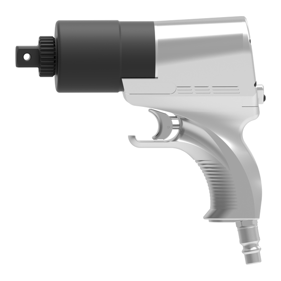
The jGun pneumatic socket wrench is a tool used for both your torque and tension applications. Different reaction arms and sockets can be used with the tool. HYTORC pneumatic tools have a repeatable accuracy of ± 5%. The air consumption is up to 1,500 l/min. - Page 13 Description Air pressure regulator Oil filter reservoir Air lubrication knob Water filter reservoir Switch of oil filter reservoir Compressed air inlet 47 - 001 -...
-
Page 14: Pneumatic Socket Wrench
Description Pneumatic socket wrench Hose connection Square drive for socket connection Air exhaust Spline for connection of reaction arm Trigger switch Tighten/loosen switch Accessories 3.5.1 Safety lever The safety lever makes sure that the tool is always used with both hands and therefore reduces the risk of injury. -
Page 15: Low-Noise Muffler
3.5.2 Low-noise muffler The low-noise muffler decreases the sound emission of the tool to 80 dB. Caution: • HYTORC recommends to calibrate the tool after: • the modification of the tool. • the replacement of the low-noise muffler. The low-noise muffler has an effect on the torque output. -
Page 16: Silencer System
Description Part number 10187723 Part number 10138922 J-.25 DSP-.25 DSP-5 J-.5 DSP-.5 DSP-8 DSP-1 DSP-2 DSP-3 3.5.3 Silencer system Caution: • Do not modify the silencer system in any way. • Only use a single silencer system hose with a maximum length of 4 m (13 ft.). - Page 17 Description Procedure Place the BoltSafe load tester between the nut and mounting surface. 47 - 001 -...
-
Page 18: Installation
Installation Installation Pneumatic hoses The working pressure of the pneumatic hoses is up to 6.2 bar. The safety factor of the pneumatic hoses is factor 4. 4.1.1 Pneumatic hose connections Use a single pneumatic hose with a maximum length of 4 m (13 ft.) to connect the FRL to the tool. -
Page 19: Disconnecting The Pneumatic Hoses
Connecting the air supply Warning: • When you operate the tool in areas with explosion hazard, use nitrogen instead of air. Contact your local HYTORC representative for more information. 47 - 001 -... - Page 20 Installation Procedure Connect the air supply to the compressed air inlet (F). Use an air hose with an internal diameter larger than 3/4". HYTORC recommends to use an air hose with an internal diameter of 1". Note: • The air supply pressure must be between 6.2 bar (90...
-
Page 21: Reaction Arms
Reaction arms Reaction arms The reaction arms can be used together with hydraulic tools, pneumatic tools and electric tools. There are different types of reaction arms to operate the tool. Standard reaction arm (360°) The length of the reaction arm is fixed. One standard heavy-duty socket must be used together with the reaction arm. -
Page 22: Straight Tpf Reaction Arm
Reaction arms Procedure Place the socket over the nut as far as possible. Place the reaction arm as shown. Adjust the reaction arm as close to the flange surface as possible. Place the tool as shown. Straight TPF reaction arm The length of the reaction arm is adjustable. -
Page 23: Straight Wtct Reaction Arm With Reaction Cup
Reaction arms Straight WTCT reaction arm with reaction cup The length of the reaction arm is adjustable. One standard heavy-duty socket must be used together with the reaction arm. Procedure Place the socket over the nut as far as possible. Place the reaction arm as shown. -
Page 24: Curved Reaction Arm With Dual-End Reaction Cup
Reaction arms Curved reaction arm with dual-end reaction cup The length of the reaction arm is fixed. Procedure Place the socket over the nut as far as possible. Place the reaction arm as shown. Make sure that the reaction cups are placed over the reaction points completely. -
Page 25: Adjustable Length
Reaction arms Procedure Place the socket over the nut as far as possible. Place the reaction arm as shown. Place the tool as shown. 5.7.2 Adjustable length The length of the reaction arm is adjustable. One standard heavy-duty socket must be used together with the reaction arm. -
Page 26: U-Shaped Dual-Tool Interconnect Reaction Arm
Reaction arms Procedure For the lowest reaction force, choose a reaction point as far away as possible. Place the reaction arm as shown. Place the sockets over the nuts as far as possible. Place the tools as shown. U-shaped dual-tool interconnect reaction arm The length of the reaction arm is adjustable. -
Page 27: Reaction Ring
Reaction arms Procedure Place the sockets over the nuts as far as possible. Place the reaction arm as shown. Place the tools as shown. 5.11 Reaction ring Multiple standard heavy-duty sockets must be used together with the reaction arm. Procedure Place the sockets over the nuts as far as possible. -
Page 28: Reaction Strip (Recessed Bolt Heads)
Place the reaction arm as shown. Place the tool as shown. 5.13 HYTORC Washer ™ double-drive socket Procedure Place the HYTORC Washer ™ under the regular nut. Place the double-drive socket with the tool over the nut and reaction washer completely. 5.14 HYTORC LoadDISC ™... -
Page 29: Hytorc Nut ™ Drive
Reaction arms Procedure Place the HYTORC LoadDISC ™ under the regular nut. Place the double-drive socket with the tool over the nut and reaction washer completely. Lock the double-drive socket with the tool onto the reaction washer using the locking lever. -
Page 30: Offset-Link
Reaction arms 5.16 Offset-link Procedure Place the offset-link over the nut. Place the reaction arm as shown. Place the tool as shown. 47 - 001 -... -
Page 31: Securing The Sockets And Reaction Arms
Securing the sockets and reaction arms Securing the sockets and reaction arms Sockets and reaction arms must be secured to prevent injuries and damage to the equipment. There are different types of heavy-duty sockets to use with the tool: 6-point sockets / 12-point sockets (regular / high) 6-point hex sockets / 12-point hex sockets (regular / high) Eccentric sockets Customized sockets... -
Page 32: Securing The Sockets (Type 2)
Securing the sockets and reaction arms Securing the sockets (type 2) Procedure Fit the securing clip (B) to the socket (A) as shown. Securing the reaction arm onto the spline shaft Procedure Slide the reaction arm (A) over the drive shaft (B) as shown. Make sure that the hex bolt (C) aligns with the hole (D). -
Page 33: Operation
Operation Operation Inspections before use Make sure that: • the air supply is correct. • the air supply is fully unrolled and not kinked, twisted or damaged. • all couplings and other connections are tight and not damaged or deformed. •... -
Page 34: Torque
Operation Torque 7.3.1 Pressure/torque chart The maximum operating pressure for all HYTORC FRLs is 6.2 bar (90 psi). Warning: • Make sure that the maximum operating pressure of the FRL is not higher than the maximum permitted pressure of 6.2 bar (90 psi). -
Page 35: Direction Of Rotation
Operation Direction of rotation 7.4.1 Determining the direction of rotation Caution: • When you use fasteners with a left handed thread, the directions of LOOSEN and TIGHTEN are the opposite. Procedure To tighten a bolted connection, place the tool onto the bolt as LOOSEN shown. -
Page 36: Tightening A Bolted Flange Connection
Always set the pressure as low as possible to loosen the nut or bolt. • If you must constantly use a high torque to loosen the nut or the bolt, use a heavier HYTORC tool. Contact your local HYTORC representative for more information. Procedure Make sure that the direction of rotation is set correctly. -
Page 37: Maintenance
• Make sure that the tool are free of dirt and dust. • Clean dirty hose couplings. Replace defective hose couplings. Maintenance by HYTORC • Have the tool disassembled, cleaned, inspected and lubricated at least once a year. • When the tool is dirty because of sand or another abrasive, have the tool fully disassembled, cleaned, inspected and lubricated immediately. - Page 38 Maintenance Procedure Hold the drain of the water filter reservoir between two fingers. Push and hold the drain button (A) until the water filter reservoir is empty. 47 - 001 -...
-
Page 39: Troubleshooting
60-90 seconds. The air supply is moist. Make sure that the air supply is dry. The air motor is defective. Contact your local HYTORC representative. The gearbox is defective. Contact your local HYTORC representative. The tool leaks externally. -
Page 40: Technical Data
Technical data Technical data 10.1 Single Speed 10.1.1 jGun J-.25 Drive 3/4" Radius (R) 31.8 mm 1.25" Length (L) 181.6 mm 7.15" Height (H) 179.3 mm 7.06" Width (W) 69.1 mm 2.72" Weight 3.3 kg 7.2 lbs. Minimum torque 68 Nm 50 ft.lbs. -
Page 41: Jgun J-1
Technical data 10.1.3 jGun J-1 Drive 3/4" Radius (R) 31.8 mm 1.25" Length (L) 224.0 mm 8.82" Height (H) 179.3 mm 7.06" Width (W) 69.1 mm 2.72" Weight 4.0 kg 8.8 lbs. Minimum torque 407 Nm 300 ft.lbs. Maximum torque 1,627 Nm 1,200 ft.lbs. -
Page 42: Jgun J-8
Technical data 10.1.7 jGun J-8 Drive 1 1/2" Radius (R) 38.1 mm 1.50" Length (L) 353.1 mm 13.90" Height (H) 214.9 mm 8.46" Width (W) 107.4 mm 4.23" Weight 13.75 kg 30.32 lbs. Minimum torque 2,475 Nm 1,825 ft.lbs. Maximum torque 10,711 Nm 7,900 ft.lbs. -
Page 43: Jgun Dsp-5
Technical data 10.2.2 jGun DSP-1 Drive 3/4" Radius (R) 31.8 mm 1.25" Length (L) 273.3 mm 10.76" Height (H) 226.6 mm 8.92" Width (W) 75.9 mm 2.99" Weight 4.4 kg 9.7 lbs. Minimum torque 428 Nm 315 ft.lbs. Maximum torque 1,660 Nm 1,225 ft.lbs. -
Page 44: Jgun Dsp-8
Technical data Maximum torque 7,050 Nm 5,200 ft.lbs. Rundown rpm Final torque rpm 10.2.6 jGun DSP-8 Drive 1 1/2" Radius (R) 62.0 mm 2.44" Length (L) 390.6 mm 15.38" Height (H) 214.9 mm 8.46" Width (W) 115.8 mm 4.56" Weight 13.4 kg 28.8 lbs. -
Page 45: Jgun A1-Z
Technical data Maximum torque 1457 Nm 1,075 ft.lbs. Rundown rpm Final torque rpm 10.3.2 jGun A1-Z Drive 3/4" Radius (R) 50.0 mm 1.98" Length (L) 303.0 mm 11.92" Height (H) 241.0 mm 9.47" Width (W) 84.0 mm 3.29" Weight 6.9 kg 15.18 lbs. - Page 46 1 ft.lbs. = 1.356 Nm 1 Nm = 0.738 ft.lbs. Note: If the area of the hex drive is smaller than the square drive, HYTORC will dis- claim any liability for broken hex drives or hex sockets. These male hex sockets are excluded from warranty claims: •...
-
Page 47: Declaration Of Conformity
Declaration of Conformity Declaration of Conformity Declaration of Conformity (according to Annex II.1.A of the Machinery Directive) HYTORC BV Platinawerf 8, 6641 TL Beuningen The Netherlands declare under our own responsibility: We are the manufacturer of the jGun pneumatic socket wrench with optional accessories.
Need help?
Do you have a question about the jGun Series and is the answer not in the manual?
Questions and answers