Envirovent PIV, MIV Manual
- Installation and user manual (17 pages) ,
- Installation manual (24 pages) ,
- Installation manual (25 pages)
Advertisement
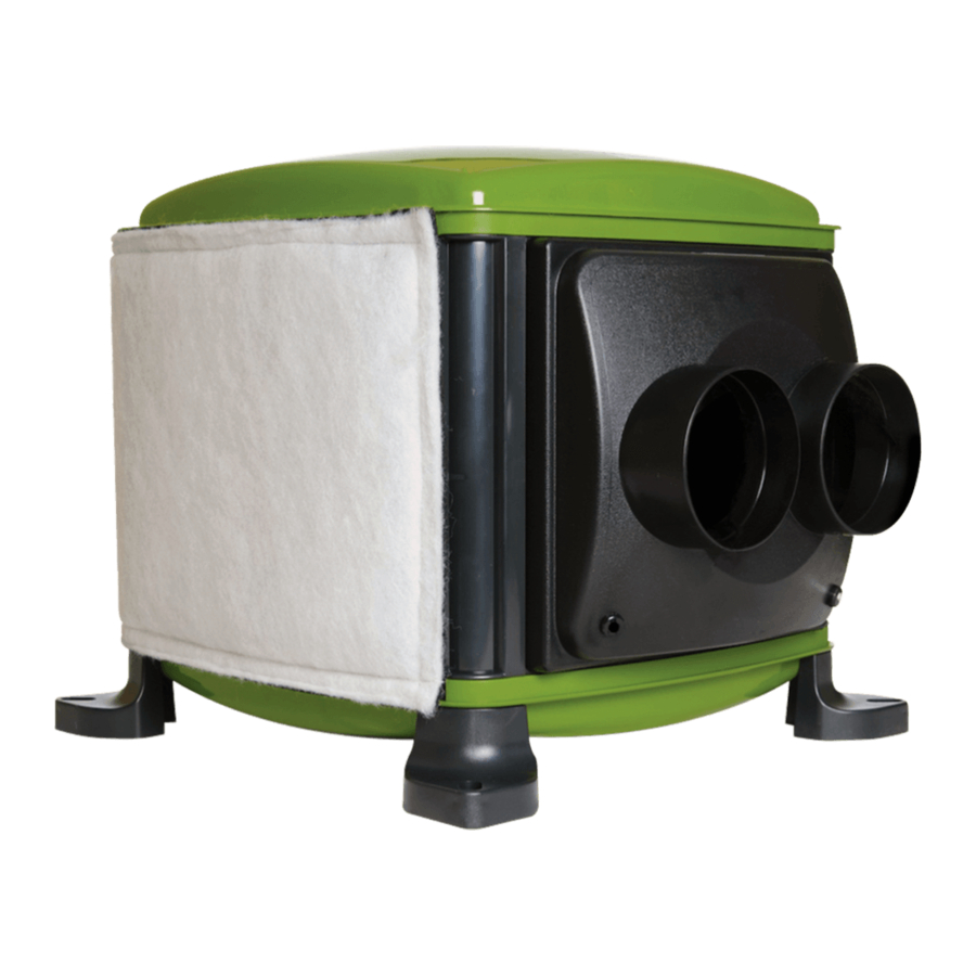
Diagrams
PIV

MIV

FILTER

KEYPAD

- Airflow 1
- Airflow 2
- Airflow 3
- Airflow 4
- Temperature <19 0 C
- Temperature >19 0 C
- Temperature >25 0 C
- Top button
- Numeric Display
- Bottom button
WIRING

The local isolator must be connected to the mains as part of the fixed wiring. Connect the N, L and E cores of the power cable to the matching terminals on the local isolator.
- Remove base cap (two screws)
![]()
- Make small hole in grommet and thread 2 core cable through
![]()
- Wire in 2 core cable
![]()
- Replace base cap (two screws)
![]()


PIV box contents
- 1x PIV unit
- 1x 200mm diffuser (+ 2x blanking plates)
- 1x Instruction guide
- 1x Diffuser mounting template
- 1x Flexible duct (1m x 200mm dia.)
- 1x Unswitched fuse spur
- 1x Remote control (Wireless units)
- 8x Foam pads
- 4x Washers
- 4x Screws 10g x 3"
- 4x Screws 10g x 1.5"
- 4x Screws 8g x 1.5"
- 4x Screws 8g x 1"
- 4x Plasterboard plugs
- 1x Roll of fixing tape
MIV box contents
- 1x MIV unit
- 2x 100mm diffusers
- 1x Instruction guide
- 2x Flexible ducts (3m x 100mm dia.)
- 1x Unswitched fuse spur
- 1x Remote control (Wireless units)
- 8x Foam Pads
- 4x Washers
- 4x Screws 10g x 3"
- 4x Screws 10g x 1.5"
- 4x Screws 8g x 1.5"
- 4x Screws 8g x 1"
- 4x Plasterboard Plugs
- 1x Roll of fixing tape
Pre - Installation Checklist
- Does the unit fit through the loft hatch?
- Check there are no obstructions in the hallway or landing where the diffuser is to be fitted and in the loft space above.
- Ensure the loft has adequate cross-flow ventilation to provide a supply of fresh air to the unit.
- Check that all partition walls are intact. Seek building advice if any are missing or broken.
- Check for flued appliances drawing air from the loft, the user should be made aware of any of these.
- Check that any flue passing through the loft is undamaged. Seek building advice if any are damaged or broken.
- Repair any ceiling gaps which allow air leakage into the loft.
- Ensure any loft water storage tanks are covered and sealed.
About PIV and MIV units
Positive Input Ventilation (PIV) and Multiple Input Ventilation (MIV) units create fresh and healthy living environments by supplying filtered air into a property at a continuous rate through ceiling mounted diffusers. The diffusers are normally installed in a hallway or landing area. The units have been developed to improve indoor air quality and reduce condensation and mould problems.
In conditions between 19°C - 25°C the units will increase air flow rate by 10%. In hot conditions above 25°C the units will temporarily switch off to avoid bringing hot air into the property from the loft space.
The PIV Unit uses a single 200mm diffuser to provide air into a hallway or landing area.
The MIV unit uses two 100mm diffusers to provide airflow to separate locations within the building. It is normally required for applications where:
- The hallway is small.
- Limited heating is available.
- The loft hatch fills the hallway ceiling.
- Airflow is required in a remote area such as a bedroom.
Option 1
If a higher airflow is required in the hallway, position that diffuser a shorter distance from the unit.

Option 2
If a similar airflow is required in the hallway, position both diffusers at similar distances from the unit.

Installation
- Place a dust sheet below the required ceiling diffuser position and check the ceiling below and loft space above are unobstructed.

-
- For PIV mark a 222mm diffuser hole using the template.

- For MIV mark two 105mm diffuser holes (see positioning information).

- For PIV mark a 222mm diffuser hole using the template.
- Wearing a dust mask and eye protection, cut out the hole/s.

-
- Screw the feet of the unit onto two 25mm x 50mm wood battens using the four 10g x 1.5" screws. (Battens not supplied).

- Position the unit with anti-vibration pads and washers onto the loft ceiling joists as in the diagram.

- Screw the battens to the ceiling joists using the four 10g x 3" screws.

- If the loft insulation sits above the joists and impedes the unit, create a raised wooden platform to mount onto.

- Screw the feet of the unit onto two 25mm x 50mm wood battens using the four 10g x 1.5" screws. (Battens not supplied).
- Insert the diffuser spigot into the ceiling hole so that the diffuser outlets face towards the walls then mark the four fixing holes.

- Attach the duct to the spigot of the diffuser and seal the connection using the fixings supplied.

- Insert the diffuser spigot into the hole then fix it in place.Use the four plasterboard plugs and four 8g x 1.5".
Then clip the diffuser cover into the diffuser spigot.

- Attach the flexible duct to the spigot on the unit and ensure it is pulled taught. Seal the connection tightly using the fixings supplied.
Cut the duct to length if required.

- With the mains supply isolated, wire the power cable into the unswitched fuse spur then wire the unswitched fuse spur into the mains supply (see wiring diagram).
Use two of the 8g x 1" screws to attach the spur to a loft joist.

- Unit can be wired to a heater enable switch (not included). Wire into the connection located under the unit (cable not included) and fit it in an accessible area.Do NOT wire into mains or any other power source. Use two of the 8g x 1" screws to attach the switch to the wall.

- Reconnect the electrical supply to the unit. Air should begin to flow from the diffuser. Press button 1 to show current air flow rate.

- Further presses will cycle through the air flow rate settings.


Fire Safety
Fire Kits
For installations with a floor more than 4.5m above ground, a compatible fire kit must be fitted. The kits listed below contain all the extra parts and instructions required:
| Order Code | Description |
| KIT-PIV-SMOKE-200 | 200mm fire-rated diffuser for PIV units only |
| KIT-MIV-SMOKE-125 | 2x 125mm fire-rated diffusers for MIV units only |
Smoke Alarms
For installations with a floor more than 4.5m above ground, the unit should be wired into a smoke alarm, in order to switch the unit off upon the detection of smoke. A smoke alarm kit is available using order code 1ACSMOKEALARM-KIT. The unit can also be wired into an existing smoke alarm (check compatibility with the smoke alarm manufacturer). All wiring should be completed by a competent person.
To test the installation, press the TEST button on top of the smoke alarm and keep it pressed until the PIV unit switches off (LEDs on the board go out).
SMOKE ALARM WIRING

Wireless Remote Control

- To indicate the current status of the unit:
- Press the remote-control button once and the LEDs will light up according to the current status of the unit.
- To modify the air flow rate:
- Press the remote-control button once
- Further presses will then cycle the unit through each of the air flow rate settings – 1, 2, 3, 4
- Further presses will cycle back through the same settings
- To enable/disable the automatic comfort heater function:
- This function is enabled by default.
- Press the remote-control button once.
- Press again for 5 seconds to disable comfort heater function.
- AUTO LED will flash red for 5 seconds.
- Press again for 5 seconds to enable comfort heater function.
- AUTO LED will light constant red for 5 seconds.
Pairing an additional remote-control:
- Turn the unit off at the isolation point.
- Restore power; for 20 seconds from restart the unit will be in pairing mode.
- Press the remote-control button once within the 20 seconds and the control will pair to the unit.
- Successful pairing is indicated by a green light on the remote.
Remote-control batteries
When the battery needs to be replaced, unscrew the switch front cover. The battery is located on the back of the cover. Battery type 3V Lithium CR2032. The switch will remain paired with the unit after battery replacement. Ensure the new battery is inserted with correct polarity, and the removed battery is safely disposed of.

Wired comfort heater enable/disable
A switch to enable/disable the heater function can be connected up to 3 metres away from the unit. This must be a volt free contact. Do not wire the cable or switch into the Mains. When the switch is pressed on, the comfort heater function is enabled and the system will maintain the incoming air temperature at 10°C. When the switch is pressed off, the automatic comfort heater function is disabled.
Energy Usage and Airflow Performance
| House size setting | Max air flow rate (l/s)a | Power usage (Watts)b |
| 1. | 21 | 4 |
| 2. | 29 | 4 |
| 3. | 38 | 6 |
| 4. | 49 | 9 |
a Diffuser installed without blanking plates fitted. b Power usage shown with comfort heater function disabled.
Running costs
| Please scan our QR code to see the annual running costs of this product. |  |
| Or visit: envirovent.com/annual-running-costs | |
Spares/Accessories
| Item Description | Order Code |
| Replacement coarse particle filter (ISO Coarse 65%) | FILTERPIV-COARSE |
| Replacement medium particle filter (ePM10 50%) | FILTERANC-MEDI |
| Replacement fine particle filter (ePM2.5 50%) | FILTERANC-FINE |
| Replacement coarse particle filter including carbon (ISO coarse 65% including carbon) | FILTERANC-COARSE+C |
| Replacement 200mm diffuser | 1DIFEVLDIF |
| Replacement 100mm diffusers | 1DIFEVLSML1 |
| Fixing kit | FIXINGKITEVL |
| Heater switch* | HEATER ENABLE SWITCH |
| Smoke alarm** | 1ACSMOKEALARM-KIT |
*Additional two core cable required.
**Additional four core cable required.
Maintenance
EnviroVent recommend that filters are checked regularly and replaced as required. The unit should be isolated from the mains when replacing or cleaning filters.
Areas with high particulate matter for example industrial areas, or higher-grade filters will become clogged quicker and will need replacing more frequently. Spare and replacement filters must be genuine EnviroVent parts.
Failure to maintain the unit as recommended may breach the terms of the warranty. See full warranty terms and conditions for further information.
Safety
Read and understand these instructions before beginning installation. The unit should be installed by a competent person.
Location
Check there is space for the unit in your chosen location. The unit must not affect the operation of open-flue appliances. Consult local regulations or a qualified gas engineer.
The open sides of the diffuser must face a minimum 1m unobstructed path away from any smoke detectors. If the diffuser cannot be repositioned, up to two sides can be closed using the plastic blanking plates. In this configuration the open sides must face a minimum 1.5m unobstructed path away from any smoke detectors. If using the 100mm diffusers, no blanking plates are supplied and the diffusers must be repositioned.
In properties with a floor above 4.5m fire diffusers must be fitted a minimum of 1m away from the smoke detectors instead of the included plastic diffusers.
Partition walls between buildings must be complete with any breaks filled.
In properties with a floor more than 4.5m above ground level the unit must be wired into a smoke alarm (see wiring information).
The appliance is considered suitable for use in countries with a warm damp equable climate, but may also be used in other countries.
Wiring Regulations
All wiring must comply with Building Regulations and the current IET Wiring Regulations (BS7671 in the UK) or equivalent standards for other countries. The final installation should be examined and tested by a qualified electrician.
This product is not suitable for use with a Type AC RCD ![]()
Electrical Connection
The unit must be earthed and a suitable isolator with a minimum contact separation of 3.0mm must be used to provide insulation for the unit. The unit must be able to be disconnected from the mains supply after installation. When wiring the unit, the included unswitched fuse spur should be incorporated in the fixed wiring.
The power supply cable running into the unit must remain the supplied flexible cable (not a solid core lighting cable). If the power supply cable becomes damaged, it must be replaced by EnviroVent, an authorised service agent for your region/country, or a similarly qualified person in order to avoid a hazard. Do not remove or tamper with any electronic components inside the product.
Users
The unit is not intended for use by persons (including children) with reduced physical, sensory or mental capabilities or lack of experience and knowledge, unless they have been given supervision and usage instruction by a person responsible for their safety. Children should be supervised to ensure they do not play with the unit. Cleaning and user maintenance must not be performed by children.
Documents / Resources
References
Download manual
Here you can download full pdf version of manual, it may contain additional safety instructions, warranty information, FCC rules, etc.
Advertisement


Need help?
Do you have a question about the PIV and is the answer not in the manual?
Questions and answers