Vulcan-Hart SG4C Service Manual
Sg4 & sg6 series full size gas convection ovens
Hide thumbs
Also See for SG4C:
- Installation & operation manual (25 pages) ,
- Catalog of replacement parts (16 pages) ,
- Service manual (56 pages)
Table of Contents
Advertisement
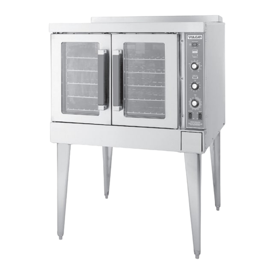
Model SG4D
For additional information on Vulcan-Hart or to locate an authorized parts
and service provider in your area, visit our website at www.vulcanhart.com
VULCAN-HART
DIVISION OF ITW FOOD EQUIPMENT GROUP, LLC
WWW.VULCANHART.COM
This manual is prepared for the use of trained Vulcan Service
Technicians and should not be used by those not properly
qualified. If you have attended a Vulcan Service School for this
product, you may be qualified to perform all the procedures
described in this manual.
This manual is not intended to be all encompassing. If you have
not attended a Vulcan Service School for this product, you
should read, in it's entirety, the repair procedure you wish to
perform to determine if you have the necessary tools, instruments
and skills required to perform the procedure. Procedures for
which you do not have the necessary tools, instruments and
skills should be performed by a trained Vulcan Service
Technician.
Reproduction or other use of this Manual, without the express
written consent of Vulcan-Hart, is prohibited.
SERVICE MANUAL
SG4 & SG6 SERIES
FULL SIZE GAS
CONVECTION OVENS
MODELS
SG4D
SG4C
SG6D
SG6C
- NOTICE -
P.O. BOX 696, LOUISVILLE, KY 40201-0696
– 1 –
ML-114875
ML-114876
ML-114877
ML-114878
TEL. (502) 778-2791
FORM 35626 Rev. A (02-08)
Advertisement
Table of Contents

Subscribe to Our Youtube Channel
Related Manuals for Vulcan-Hart SG4C


Summary of Contents for Vulcan-Hart SG4C
- Page 1 ML-114878 Model SG4D - NOTICE - This manual is prepared for the use of trained Vulcan Service Technicians and should not be used by those not properly qualified. If you have attended a Vulcan Service School for this product, you may be qualified to perform all the procedures described in this manual.
- Page 2 – 2 – © VULCAN-HART, 2008...
-
Page 3: Table Of Contents
TABLE OF CONTENTS GENERAL ................................5 Introduction ............................... 5 Installation ..............................5 Operation ..............................5 Cleaning ..............................5 Lubrication ..............................5 Specifications ............................5 Electrical Data ............................ 5 Gas Data ............................. 5 Tools ................................. 5 Standard ............................. 5 Special ..............................5 REMOVAL AND REPLACEMENT OF PARTS ..................... - Page 4 Door Catch Roller Adjustment ......................... 29 ELECTRICAL OPERATION ..........................30 Component Description ........................... 30 Plug, Socket and Components (SG4D/SG6D) ..................31 Plug, Socket and Components (SG4C/SG6C) ..................32 Sequence of Operations ..........................33 SG4D/SG6D with Solid State Temperature Controller ..............33 Cook Cycle ............................33 Timer Cycle ............................
-
Page 5: General
Models SG4D and SG6D are equipped with solid state-controls and a 60-minute timer (a 5-hour timer is optional). Models SG4C and SG6C have a computer control with built-in Roast & Hold. Models SG6D and SG6C have a 4" deeper cavity than models SG4D and SG4C. Gas Data... -
Page 6: Removal And Replacement Of Parts
REMOVAL AND REPLACEMENT OF PARTS COMPONENT LOCATION TOP VIEW BLOWER MOTOR OVEN LIGHTS COOLING TEMPERATURE PROBE COMPONENT GAS BURNERS PANEL IGNITER & GAS VALVE FLAME SENSE DOOR CONTROL SWITCH PANEL HIGH LIMIT PL-56044 – 6 –... -
Page 7: Covers And Panels
Control Panel COVERS AND PANELS 1. Remove three screws on the right side which secure the control panel. Pull the panel away Disconnect from the oven. electrical power to the machine and follow lockout / tagout procedures. CONTROL Top Front Cover PANEL 1. -
Page 8: Control Panel Components
L I G H T S W I T C H L I G H T S W I T C H SG4D/SG6D SG4C/SG6C PL-56046 PL-56045-1 Procedure Disconnect the electrical power to the machine and follow lockout / tagout procedures. -
Page 9: Component Panel Components
BLOCK BLOCK ASSEMBLY ASSEMBLY SG4D/SG6D PL-56047 SG4C/SG6C PL-56048 Procedure Disconnect the electrical power to the machine and follow lockout / tagout procedures. 1. Remove the right side panel as outlined under Covers and Panels. 2. Disconnect the wire leads to the component being replaced. -
Page 10: Temperature Probe
Covers and Panels. 2. Disconnect probe leads from the solid state temperature controller on the SG4D/SG6D or the computer controller on the SG4C/SG6C. 3. Remove the racks and right rack support. 4. Remove the upper and lower door seals. SG4C/SG6C Temperature Probe Shown 8. -
Page 11: Gas Burners
GAS BURNERS 5. Reverse the procedure to install and check for proper operation. A. Ensure the spacers are in place on the Disconnect the ignition wires. The spacers are intended electrical power to the machine and to keep the ignition wires from laying flat follow lockout / tagout procedures. -
Page 12: Gas Orifice
3. Disconnect compression fittings from the GAS ORIFICE valve. Disconnect electrical power to the machine and follow lockout / tagout procedures. Shut off the gas before servicing the oven. 1. Remove the lower front cover as outlined under Covers and Panels. 2. -
Page 13: Ignition Control Module
IGNITION CONTROL MODULE SPARK IGNITER AND FLAME SENSE Disconnect Disconnect electrical power to the machine and electrical power to the machine and follow lockout / tagout procedures. follow lockout / tagout procedures. 1. Remove the right side cover as outlined Shut off the gas before servicing under Covers and Panels. -
Page 14: Blower And Motor
5. Remove the screws that secure the motor BLOWER AND MOTOR mounting plate to the rear wall. Disconnect electrical power to the machine and follow lockout / tagout procedures. 1. Remove racks. 2. Remove the screws securing the snorkel and remove the snorkel. -
Page 15: Oven Doors And Bearings
OVEN DOORS AND BEARINGS FRONT VIEW OF MOTOR FROM INSIDE OVEN CAVITY Disconnect electrical power to the machine and follow lockout / tagout procedures. 1. Remove the top front cover and bottom front cover as outlined under Covers and Panels. 2. -
Page 16: Roller Latch Assembly
7. The top and bottom bearings are now DOOR CATCH ROLLER ASSEMBLY accessible for inspection and/or replacement (INDEPENDENT DOORS) if needed. NOTE: For units with serial number starting with 48 A. If bearings are OK, proceed to step 8. made before 8/13/07 and serial number starting with B. -
Page 17: Door Switch
2. Remove the door handle, then remove the DOOR SWITCH outer door panel. 3. Lift out the inner door panel window assembly. Disconnect 4. Remove the door seal from the inside of the electrical power to the machine and left door only. follow lockout / tagout procedures. -
Page 18: High Limit Thermostat
INTERIOR LIGHTS HIGH LIMIT THERMOSTAT Disconnect Disconnect electrical power to the machine and electrical power to the machine and follow lockout / tagout procedures. follow lockout / tagout procedures. 1. Remove the racks from the oven. 1. Remove the top four racks from the oven. 2. -
Page 19: Cooling Fan
5. Attach the lead wires to the replacement Fan Installation Tips socket. • The fan must be installed so air is pulled from NOTE: Ensure the case is connected to the the rear of the oven and blown into the control green ground wire. -
Page 20: Service Procedures And Adjustments
SERVICE PROCEDURES AND ADJUSTMENTS Certain procedures in this section require electrical test or measurements while power is applied to the machine. Exercise extreme caution at all times. If test points are not easily accessible, discern power, attach test equipment and reapply power to test. 8. -
Page 21: Solid State Temperature Controller Calibration (Sg4D/Sg6D)
7. Calculate the average oven temperature by b. If incorrect, check temperature probe as adding the actual minimum temperature to outlined under Temperature Probe Test the actual maximum temperature and dividing (SG4D/SG6D). by 2. 1) If temperature probe is functioning EXAMPLE: properly and the temperature Oven set to 350°F. -
Page 22: Temperature Probe Test (Sg4D/Sg6D)
TEMPERATURE PROBE TEST (SG4D/SG6D) Disconnect the electrical power to the machine and follow lockout / tagout procedures. The temperature probe used in conjunction with the Solid State Temperature controller is an RTD (resistance temperature detector) of the Thermistor type. As temperature increases the resistance value decreases. Test Steps 1. -
Page 23: Computer Controller (Sg4C/Sg6C)
3. Listed are the parameters and data in the COMPUTER CONTROLLER setup mode. (SG4C/SG6C) Operation Refer to the Installation & Operation Manual for specific operating instructions. Setup Mode Use the setup mode to verify that the control is configured to the factory settings which result in the proper operation of the oven. -
Page 24: Solid State Relay Test
A. If no voltage is present, solid state relay 6. Enter the setup mode as outline in Setup is not functioning properly. Mode under Computer Control (SG4C/SG6C). 1) Replace the SSR and check for proper A. Advance through the menu until CAL1 operation. -
Page 25: Gas Pressure Adjustment
4. Install hose barb adapter and attach GAS PRESSURE ADJUSTMENT manometer tube. Disconnect electrical power to the machine and follow lockout / tagout procedures. Accurate gas pressure adjustments can only be made with the gas on and the burner lit. If the incoming line pressure to the valve is less than the minimum stated, then the manifold pressure cannot be set correctly. -
Page 26: Verification Of Spark At Igniter
The following steps require power VERIFICATION OF SPARK AT IGNITOR to be applied to the unit during the test. Use extreme caution at all times. Disconnect 4. Plug the oven in and set the temperature electrical power to the machine and controller to the maximum setting. -
Page 27: Flame Current Measurements
BLOWER ADJUSTMENT FLAME CURRENT MEASUREMENT Disconnect MICROAMP METER electrical power to the machine and follow lockout / tagout procedures. 1. Remove the blower motor and mounting assembly as outlined under Blower and FENWAL DUAL CHANNEL Motor in Removal and Replacement of Parts. IGNITION 345519-4 MODULE... -
Page 28: Door Adjustment
DOOR ADJUSTMENT DOOR STRIKE ADJUSTMENT (INDEPENDENT DOORS) NOTE: For units with serial number starting with 48 Disconnect made after 8/12/07 and serial number starting with 54 electrical power to the machine and made after 8/26/07. follow lockout / tagout procedures. 1. -
Page 29: Door Catch Roller Adjustment
6. Place a standard flat screwdriver through the DOOR CATCH ROLLER ADJUSTMENT opening in the top channel into the slot in the cylinder of the catch assembly. NOTE: For units with serial number starting with 48 made before 8/13/07 and serial number starting with 54 made before 8/27/07. -
Page 30: Electrical Operation
ELECTRICAL OPERATION No Ignition Light (SG4C/SG6C) - Lit when power is COMPONENT DESCRIPTION turned ON, during ignition trial and gas purge time and when no flame is detected by flame sensor. If the oven fails to ignite after three attempts, it will remain Master Switch (S1) - Determines the mode of lit until power is reset. -
Page 31: Plug, Socket And Components (Sg4D/Sg6D)
Plug, Socket and Components (SG4D/SG6D) CONTROL PANEL COMPONENT PANEL (REAR VIEW) (FRONT VIEW) PORCELAIN BLOCK ON/OFF/ ASSEMBLY COOLDOWN SWITCH TRANSFORMER HEAT INDICATOR LIGHTS 3 LT NO IGNITION 5 COM 6 3 NO 2 (COM AC) SOLID STATE 4 (120VAC) THERMOSTAT IGNITION 9 (240VAC) CONTROL... -
Page 32: Plug, Socket And Components (Sg4C/Sg6C)
Plug, Socket and Components (SG4C/SG6C) CONTROL PANEL COMPONENT PANEL (REAR VIEW) (FRONT VIEW) PORCELAIN BLOCK ASSEMBLY 2J (FEMALE) TRANSFORMER SOLID STATE 3J (FEMALE) LOAD RELAY (SSR1) OPER. TEMP. PIN NUMBERS 0-30 DEG. C 12 9 11 8 1 EVENT 2 OUT... -
Page 33: Sequence Of Operations
2. Set temperature controller dial to desired SEQUENCE OF OPERATIONS temperature. A. Contacts J3 and J5 close. SG4D/SG6D with Solid State Temperature Controller 3. Power switch (S1) is turned ON. Schematic 424373-1 will be used to explain the NOTE: Power is available to the oven light switch electrical sequence of operation. -
Page 34: Timer Cycle
4. Heating circuit is powered. Timer Cycle A. No ignition light (red) comes ON. The timer operates independently of the heating cycle. Additional time can be set or the timer can be B. Module performs a self diagnostic test turned OFF throughout the cooking cycle. for 4 seconds. -
Page 35: Sg4C/Sg6C With Computer Controller
2. Power switch (S1) turned to COOL DOWN. SG4C/SG6C with Computer Controller A. Power to fan speed switch (S3). Set fan Schematic 426575-1 will be used to explain the speed switch to either HI or LO. electrical sequence of operation. - Page 36 C. Power to terminal 1 on solid state relay 1 B. Heat relay coil (R1) energized. SSR1-load side and solid state relay 2 1) (R1) contacts (N.O.) close and the SSR2-load side. heating circuit is powered. D. Component cooling fan energized. 2) Oven heat light on the control comes E.
-
Page 37: Temperature And Time Cycle (Normal Cooking)
Anytime the system calls for heat, the fan must be running. Function Switch SG4C/SG6C - Selects the cooking After the oven has reached the 150°F set mode of the oven between Cook or Roast and Hold. temperature, the heat and fan are de- Is used in conjunction with the Roast and Hold timer energized. -
Page 38: Wiring Diagrams
WIRING DIAGRAMS – 38 –... - Page 39 – 39 –...
-
Page 40: Schematics
SCHEMATICS BLACK WHITE 120 VOLT 200-240V C1-6 GND. POWER ON POWER SWITCH ON/OFF/COOL SHOWN ON HEATING POWER LEVEL THERMOSTAT PROBE OVEN LAMP C1-10 OVEN LAMP SWITCH OPEN C1-3 C3-1 OVEN LAMP DOOR SWITCH C1-4 C3-2 1 HOUR TIMER BUZZER HOLD WHT. - Page 41 GAS CONVECTION OVEN SG4 WITH WATLOW 734 CONTROL 426575-1 REV. C – 41 –...
-
Page 42: Troubleshooting
TROUBLESHOOTING t ' n c t i t i s c t i c t i t ' n t i s c t i v i t t ' n c t i t i s t i s f / r i r t c t i... -
Page 43: Computer Control Models Only
TROUBLESHOOTING COMPUTER CONTROL MODELS ONLY c t i . f f l l o – 43 –... -
Page 44: Error Codes
ERROR CODES u f l o i t u f l o i t F ° . l o g i f o i t u f l o i t e l i · y f i · · o i t ·...
Need help?
Do you have a question about the SG4C and is the answer not in the manual?
Questions and answers
I changed the orfices from natural gas to propane but it won't ignite. I changed the igniter board, it still won't light
Possible reasons for a Vulcan-Hart SG4C not igniting after changing the orifices from natural gas to propane include:
1. Gas supply OFF or insufficient gas pressure.
2. Manual gas valve closed.
3. Gas solenoid valve off or inoperative.
4. Igniter/flame sense malfunction or maladjusted.
5. Ignition module malfunction.
6. Transformer inoperative.
7. High limit thermostat open.
8. Interconnecting wiring malfunction.
9. Shorted electrode on igniter/flame sense.
10. Igniter cable (high voltage) open.
11. Incorrect polarity from transformer to ignition module.
12. Igniter lead connections malfunction.
13. Igniter ground inoperative.
14. Centrifugal switch in blower motor inoperative.
Also, ensure the propane gas pressure regulator is set correctly at 10" W.C. and all air is purged from the gas lines before ignition.
This answer is automatically generated