Advertisement
5 H.P. Dust Collector
(Model 50-866 Single Phase)
(Model 50-861 Three Phase)
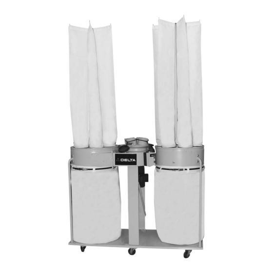
MODEL 50-861 SHOWN
PART NO.
902110 - 04-18-02
Copyright © 2002 Delta Machinery
To learn more about DELTA MACHINERY
visit our website at: www.deltamachinery.com.
For Parts, Service, Warranty or other Assistance,
1-800-223-7278 (
1-800-463-3582).
please call
In Canada call
Advertisement
Table of Contents

Subscribe to Our Youtube Channel
Related Manuals for Delta 50-861


Summary of Contents for Delta 50-861
- Page 1 (Model 50-861 Three Phase) MODEL 50-861 SHOWN PART NO. 902110 - 04-18-02 Copyright © 2002 Delta Machinery To learn more about DELTA MACHINERY visit our website at: www.deltamachinery.com. For Parts, Service, Warranty or other Assistance, 1-800-223-7278 ( 1-800-463-3582). please call...
-
Page 2: General Safety Rules
If you have any questions relative to a particular application, DO NOT use the machine until you have first contacted Delta to determine if it can or should be performed on the product. -
Page 3: Important Safety Rules For Dust Collectors
11. REPLACE a damaged cord immediately. DO NOT use a damaged cord or plug. If the dust collector is not operating properly, or has been damaged, left outdoors or has been in contact with water, take it to an Authorized Service Center for service. -
Page 4: Unpacking And Cleaning
UNPACKING AND CLEANING Carefully unpack the tool and all loose items from the shipping container(s). Remove the protective coating from all unpainted surfaces. This coating may be removed with a soft cloth moistened with kerosene (do not use acetone, gasoline or lacquer thinner for this purpose). - Page 5 1. Motor, Fan and Blower Assembly (Hardware for mounting not shown: 5/16" flat washer (4), 5/16" lockwasher (4), 5/16-18 hex nut (4) 2. Drums (2) 3. Gaskets (2) 4. Switch Control Box for Model 50-866 only.( 3 sheet metal screws for mounting) 5.
- Page 6 ASSEMBLING CASTERS TO BASE Turn base over. Align four holes in caster (A) Fig. 5, with four holes at one corner of base (B) and assemble caster to base. Place a 5/16" lockwasher (D), then a 5/16" flat washer (E) on a 5/16-18x5/8" hex head screw (C), insert the hex head screw through the hole in the wheel caster and thread the screw into the base.
- Page 7 4. NOTE: FOR MODEL 50-866 MAKE SURE THAT THE FRONT OF THE MOTOR ASSEMBLY IS ATTACHED TO THE SUPPORT WITH THREE PREDRILLED HOLES IN IT, (THESE HOLES ARE WHERE CONTROL MOUNTED).Carefully place the motor/blower assembly (F) Fig. 10, onto two side supports (A), which were assembled in STEP 2.
- Page 8 9. Fig. 15, illustrates both drums (K) assembled to the fan and blower assembly (F). ASSEMBLING DRUM SUPPORT POSTS TO BASE AND DRUMS 1. Assemble end of drum support post (A) Fig. 16, to threaded holes in one corner of base (B). Place a 5/16" lockwasher (C), on a 5/16-18 x 5/8"...
- Page 9 ASSEMBLING INTAKE PORT TO MOTOR AND BLOWER ASSEMBLY Place the intake port (A) Fig. 19, onto the flange of motor/blower assembly (B). Align the holes in the flange (B) of the motor/blower assembly with the mounting holes in the dust intake port and fasten with four sheet metal screws (C) as shown in Fig.
- Page 10 3. Assemble six-position filter bag hanger assembly (G) Fig. 23, to the top half of the upper bag support (H). Place a 5/16" lockwasher (I) onto a 5/16-18x1¼" hex head screw (J), place a special washer (K) (30mm O.D., 8mm I.D., 3mm thick), onto the screw, insert the screw through the filter bag hanger and place special washer (L) (30mm O.D., 8mm I.D., 3mm thick) onto screw.
- Page 11 (C) with the locking band (F). Assemble the remaining dust collection bag to the drum at the other side of the dust collector. NOTE: Make certain locking band (F) Fig. 29, is positioned in the channel of drum (C) before fastening clamp (A).
- Page 12 WARNING: Installation by a qualified electrician is recommended to assure safe and proper wiring and product operation. The motor rating for your single phase dust collector is 230 Volts, 5 H.P. Before connecting your dust collector to an electrical power system, be sure the electrical system agrees with the motor rating of the tool.
- Page 13 (D) Fig. 34. Replace controller cover (C). 4. The on/off buttons are located at the front of the control box (C) Fig. 35. To start the dust collector, push “ON” button (B). To stop the machine, push “OFF’” button (D).
-
Page 14: Motor Maintenance
MAINTENANCE NOTE: Before any maintenance or service is performed, be sure that unit is disconnected from power source to prevent accidental starting. MOTOR MAINTENANCE Removing dust and dirt: Blow off motor with low pressure air to remove dust or dirt. Air pressure above 50 P.S.I. should not be used, as high pressure may damage insulation and blow dirt under loosened tape. -
Page 15: Parts, Service Or Warranty Assistance
1-800-223-7278 (In Canada call 1-800-463-3582). Delta will repair or replace, at its expense and at its option, any Delta machine, machine part, or machine accessory which in normal use has proven to be defective in workmanship or material, provided that the customer returns the product prepaid to a Delta factory service center or authorized service station with proof of purchase of the product within two years and provides Delta with reasonable opportunity to verify the alleged defect by inspection. - Page 16 Parts and accessories for Porter-Cable ·Delta products should be obtained by contacting any Porter-Cable·Delta Distributor, Authorized Service Center, or Porter-Cable·Delta Factory Service Center. If you do not have access to any of these, call 800-223-7278 and you will be directed to the nearest Porter-Cable·Delta Factory Service Center. Las Estaciones de Servicio Autorizadas están ubicadas en muchas grandes ciudades.
Need help?
Do you have a question about the 50-861 and is the answer not in the manual?
Questions and answers