Advertisement
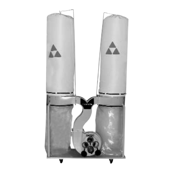
3 H.P. Single-Stage
Dust Collector
(Model 50-852, three phase)
(Model 50-853, single phase)
PART NO. 902108 - 06-27-02
Copyright © 2002 Delta Machinery
To learn more about DELTA MACHINERY
visit our website at: www.deltamachinery.com.
For Parts, Service, Warranty or other Assistance,
1-800-223-7278 (
1-800-463-3582).
please call
In Canada call
Advertisement
Table of Contents

Related Manuals for Delta 3 H.P. SINGLE-STAGE DUST COLLECTOR 50-852


Summary of Contents for Delta 3 H.P. SINGLE-STAGE DUST COLLECTOR 50-852
- Page 1 Dust Collector (Model 50-852, three phase) (Model 50-853, single phase) PART NO. 902108 - 06-27-02 Copyright © 2002 Delta Machinery To learn more about DELTA MACHINERY visit our website at: www.deltamachinery.com. For Parts, Service, Warranty or other Assistance, 1-800-223-7278 ( 1-800-463-3582).
-
Page 2: General Safety Rules
If you have any questions relative to a particular application, DO NOT use the machine until you have first contacted Delta to determine if it can or should be performed on the product. -
Page 3: Additional Safety Rules For Dust Collectors
13. REPLACE a damaged cord immediately. DO NOT use a damaged cord or plug. If the dust collector is not operating properly, or has been damaged, left outdoors or has been in contact with water, take it to an Authorized Service Center for service. -
Page 4: Unpacking And Cleaning
UNPACKING AND CLEANING Carefully unpack the tool and all loose items from the shipping container(s). Remove the protective coating from all unpainted surfaces. This coating may be removed with a soft cloth moistened with kerosene (do not use acetone, gasoline or lacquer thinner for this purpose). - Page 5 WARNING: FOR YOUR OWN SAFETY, DO NOT CONNECT THE MACHINE TO THE POWER SOURCE UNTIL THE MACHINE IS COMPLETELY ASSEMBLED AND YOU READ AND UNDERSTAND THE ENTIRE INSTRUCTION MANUAL. ASSEMBLING CASTER ASSEMBLIES TO BASE Align the holes in caster assembly (A) Fig. 5, with four holes in support stand (B) located on the underside of base (C).
- Page 6 4. Apply a bead of silicone sealant around flange of chute (F) Fig. 9. Align holes in ten-hole gasket (G) Fig. 9, with mounting holes in blower flange (F) and press gasket onto flange as shown. 5. Align mounting holes in dust chute (H) Fig. 10, with gasket (G), assembled in STEP 4.
- Page 7 7. Apply a bead of silicone sealant around flange of chute (H) Fig. 14. Align holes in eight-hole gasket (K) Fig. 14, with mounting holes in chute (H) and press gasket (K) onto flange as shown. 8. Align mounting holes in left hand drum (N) Fig. 15, with gasket (K), assembled in STEP 7.
- Page 8 13. Tighten all mounting hardware at this time. 14. Attach the lower dust bag retaining clip (A) Fig. 20, to the dust collector drum. Align the two holes in the retaining clip (A) Fig. 20, with the two holes in the drum.
- Page 9 ASSEMBLING FILTER AND DUST COLLECTION BAGS TO DRUM 1. Hook the loop on the top of filter bag (A) Fig. 22, onto filter bag support rod (B) as shown. 2. Assemble extension rod (C) Fig. 23, into the end of filter bag support rod (B).
- Page 10 5. Place the locking clamp (C) Fig. 26 around dust collection bag and dust collector drum and lock in place. NOTE: Make certain locking clamp is positioned in the channel of the dust collector drum before locking clamp.
-
Page 11: Electrical Connections
ELECTRICAL CONNECTIONS The motor rating of your dust collector is either 230/460 Volt, Three Phase; or 230 Volt, Single Phase. Before connecting the motor to the power line, make sure the switch is in the “OFF” position and be sure that the electric current is of the same characteristics as indicated on the tool. - Page 12 Your dust collector is supplied with a motor and controller; however, it is not supplied with a power cord and plug. 1. To connect the dust collector to a power system, remove controller cover (A) Fig. 34. 2. Bring the single phase power line through the access hole (B) Fig.
-
Page 13: Operating Controls
OPERATING CONTROLS ON/OFF SWITCH (Model 50-852) The “on/off” switch is located on the side of the motor stand. To turn the dust collector “ON”, push button (A) Fig. 36. To turn the dust collector “OFF”, push button (B). ON/OFF SWITCH (Model 50-853) The “on/off”... - Page 14 NOTES...
-
Page 15: Parts, Service Or Warranty Assistance
1-800-223-7278 (In Canada call 1-800-463-3582). Delta will repair or replace, at its expense and at its option, any Delta machine, machine part, or machine accessory which in normal use has proven to be defective in workmanship or material, provided that the customer returns the product prepaid to a Delta factory service center or authorized service station with proof of purchase of the product within two years and provides Delta with reasonable opportunity to verify the alleged defect by inspection. - Page 16 Delta products should be obtained by contacting any Porter-Cable · Service Center, or Porter-Cable Delta Factory Service Center. If you do not have access to any of these, call 800-223-7278 and you will · be directed to the nearest Porter-Cable Delta Factory Service Center.
Need help?
Do you have a question about the 3 H.P. SINGLE-STAGE DUST COLLECTOR 50-852 and is the answer not in the manual?
Questions and answers