Advertisement
ASSEMBLY INSTRUCTIONS
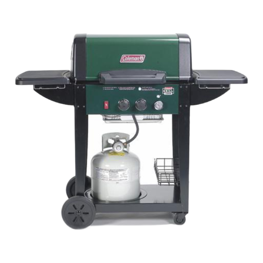
BEFORE YOU BEGIN ASSEMBLING YOUR NEW QUALITY COLEMAN GAS BARBECUE GRILL:
FOR EASE OF ASSEMBLY, leave the grill on the inside bottom foam packing tray until the wheels have been attached. (See representative example at right). Remove the outside foam from the right and left sides of the frame base at this time.
Remove all cartons located on top of the barbecue grill base and set aside.
START THE COOKING GRIDS SEASONING PROCESS BEFORE ASSEMBLING YOUR GRILL!
CAST IRON GRIDS
Cast Iron grids are on select models only.
Your cast iron grids may have some rusting. This is normal. To remove the rust, scour the rusty areas with steelwool, i.e. SOS pad, until all traces of rust are gone. Wash, dry and season grids.
SEASONING CAST IRON GRIDS
SEASONING IS THE PROCESS OF ALLOWING OIL TO BE ABSORBED INTO THE IRON, CREATING A NON-STICK, RUSTPROOF FINISH. HERE'S HOW TO DO IT:
Preheat Oven to 350ºF.
Wash with hot, soapy water and a stiff brush. Rinse and dry completely.
Oil the grids (all surfaces, top and bottom) with MELTED solid vegetable shortening.
Turn upside down on the top rack of a 350ºF pre-heated oven.
Put aluminum foil on the bottom rack to catch any excess drippings.
Bake the grids for one hour at 350ºF.
Let the grid cool slowly in the oven.
Store, uncovered, in a dry place when cooled.

CARTON A - MISCELLANEOUS PARTS
Two Wheels (16)
Two Main Control Knobs (32)
One Grease Wire (49)
One Grease Tray (49a)
Two Grease Drip pans (48)
One Perforated Tent(62)
One Meat Probe (57)
One Meat Probe Receptacle (57a)
One Handle Assembly
One Literature Bag
One 6-lobe Screwdriver
Hardware bag(s)
Assorted assembly hardware - One Igniter Kit bag
Two Axle pins (3)
Side Burner Models include the following:
One Side Burner Control Knob (40)

Combustion by-products produced when using this product contain chemicals known to the State of California to cause cancer, birth defects, or other reproductive harm.
Tools Needed
#20 6-Lobe Screwdriver (Included)
#2 Phillips Screwdriver
An adjustable wrench
9-Volt Battery (Included)
Optional Tools
7/16" and 5/16" Box End Wrenches
7/16" Nut Driver
Electric or Cordless Screwdriver
#20 6-Lobe driver bit
#2 Phillips driver bit
ONE CARTON - L.P. GAS CYLINDER
CARTON B - 1 SIDE TABLE ASSEMBLY
(FOR MODELS WITH SIDE BURNER)
ONE SIDE BURNER GRID (41)
ONE RIGHT SIDE TABLE ASSEMBLY
ONE LEFT SIDE BURNER ASSEMBLY
One bag Assorted assembly hardware
ONE CARTON-COLEMAN SIDE BURNER ASSEMBLY (FOR MODELS WITH SIDE BURNER)
Engineering Code
LD113332/LD113312
LE113332/LE113312
LE113333
LD113342*/LD113322*
LE113342*/LE113322*
LE113343*
*Cylinder not included
BEGIN WITH CARTON A - MISCELLANEOUS PARTS
Step 1
Remove outside foam ONLY from the LEFT SIDE and RIGHT SIDE of the BASE. Assemble WHEELS (16). See detail 1-A.

Step Assemble BASKET (22) on the right end of base and legs. See detail 1-B.

1-A. Insert the AXLE PINS (3) into the wheels. Insert the wheels and axle pins into each side of the base and secure with two clevis pins (WN). See diagram. Remove the remaining foam tray from under the barbecue grill now.
1-B. Feed the BASKET (22) through the right legs with the basket extensions on the outside of the legs. The extensions will rest against the outside of the legs. The extensions will rest against the outside of the legs. Place the Basket feet over the caster bolt and secure with two wing nuts (DZ).

Step 2
Assemble the two GREASE DRIP PANS (48) under the bottom casting and secure with the two GREASE PAN HANGERS (49). See detail 2-A.

2-A. Align the holes in the GREASE PAN (48) with the holes underneath the Bottom casting. Secure the Grease Pan to the bottom casting with a GREASE PAN HANGER (49). Repeat the assembly for the other GREASE PAN and GREASE PAN HANGER
Step 3
Assemble the two DISPOSABLE GREASE PANS (48a). See detail 3-A.

3-A. Place two DISPOSABLE GREASE PANS (48a) into the Grease Pan Hangers as shown.
Step 4
Assemble CONTROL KNOBS (32), MEAT PROBE RECEPTACLE (57a) and MEAT PROBE (57) in detail 4-A.
Assemble PERFORATED STAINLESS TENT (62). See detail 4-B.

4-A. Place CONTROL KNOBS (32) on valve stems.
Insert MEAT PROBE RECEPTACLE (57a) into the right side of the control panel.
Place the MEAT PROBE (57) into the meat probe receptable.
4-B. Place the PERFORATED STAINLESS TENT (62) in the slots of the PORCELAIN "I" TENT (61).
Step 5
Assemble FRONT HANDLE Assembly to the GRILL LID (55) in detail 5-A.
Assemble COOKING GRIDS (63) and WARMING RACK (65). See detail 5-B.

5-A. The FRONT HANDLE (58), HANDLE SPACER (60), HANDLE INSULATOR (59), four screws (DT) and four hex nuts (AO) are PRE-ASSEMBLED at the factory.
Remove the four hex nuts (AO) from the Handle assembly. Insert the screws in the Handle assembly into the GRILL LID (55) and secure with four hex nuts (AO).
Tighten with adjustable wrench or 7/16" wrench.

5-B. Place the COOKING GRIDS (63) in the Bottom casting with the smooth surface down.
Set the WARMING RACK (65) near the back of the bottom casting.

Step 6
BEGIN WITH CARTON B - SIDE T ABLE ASSEMBLIES
Assemble Pre-Assembled RIGHT SIDETABLE in detail 6-A.
Assemble the SIDE TABLE (9). See detail 6-B.
 Note: Use both hands and lift with side table brackets. NEVER lift with plastic parts.

6-A. Use the 6-lobe screwdriver to back out the outside screws located in the top right legs (2 or 3 turns) just enough for the SIDE BRACKETS (11 and 13) on the PRE- ASSEMBLED sidetable, to slide in place.

DO NOT Remove screws completely. Place the bottom slot of the brackets on the screws first and then the top slot. Note: The TOOL BAR (12) faces the front of the grill. Gently slide the Bracket down and tighten screws.

6-B. Place the SIDE TABLE (9) inside the side
STEPS 7 AND 8 ARE FOR THE 2000/3000 SERIES GRILL WITH TWO SIDE TABLES. IF YOU HAVE A SIDE BURNER CONTINUE ON TO STEP 10.
Step 7
Assemble Pre-Assembled LEFT SIDETABLE in detail 7-A.
Assemble the SIDE TABLE (9). See detail 7-B.
Note: Use both hands and lift with side table brackets. NEVERlift with plastic parts.

7-A. If you have a SIDEBURNER continue on to Step 11 now. Use the 6-lobe screwdriver to back out the outside screws located in the top left legs (2 or 3 turns) just enough for the SIDE BRACKETS (11 and 13) on the PRE-ASSEMBLED sidetable, to slide in place.
DO NOT Remove screws completely. Place the bottom slot of the brackets on the screws first and then the top slot. Note: The TOOL BAR (12) faces the front of the grill. Gently slide the Bracket down and tighten screws.

7-B. Place the SIDE TABLE (9) inside the side frame.
Step 8
Assemble the ELECTRODE WIRES (29), SWITCH WIRES (26) and the 9-VOLT BATTERY (30) to the ELECTRONIC MODULE (28) in details 8-A. Assemble the ELECTRONIC MODULE (28) under the Left Side Table in detail 8-B.
ELECTRONIC MODULE

8-A. Attach the black SWITCH WIRES (26), with the red connecters located on the left side of your grill, to the two large pins on the ELECTRONIC MODULE (28). Then attach the two orange ELECTRODE WIRES (29) located on the left side of your grill, to the pins on the module marked 1MB and 2MB. Insert the 9-VOLT BATTERY (30) in the module, it MUST snap in place.
Insure that the wires DO NOT touch hot surfaces such as the grill casting.

LEFT SIDE OF GRILL

8-B. On the LEFT side of the grill, locate the front SIDE BRACKET (13) and attach the ELECTRONIC MODULE (28) underneath the front bracket flange in the holes indicated in the Mounting Holes detail, with two screws (JS). Bundle extra wire length with wire tie (LA) not shown.

Step 9
Assemble the CYLINDER (79) to the Cylinder caddy. See detail 9-A.
Place the CYLINDER RETAINER WIRE (77) over the Cylinder Collar. See detail 9-B.
Attaching TYPE 1 fitting to the fuel outlet valve in detail 9-C

9-A Set CYLINDER (79) in the cylinder caddy with the outlet valve facing the front of the grill.

TO ENSURE PROPER GAS FLOW, BURNER CONTROL VALVES MUST BE "OFF" BEFORE OPENING THE GAS CYLINDER VALVE.

9-B Place the CYLINDER RETAINER WIRE (77) over the Cylinder collar, by rotating the wire from the original position toward the cylinder collar.
During assembly of grill and when attaching or replacing the L.P. gas cylinder, insure that the gas supply hose is free of kinks and/or damage and is at least 3" away from hot surfaces such as the grill casting.
9-C Insert the TYPE 1 nipple of the regulator (27) into the cylinder's fuel valve outlet as shown. Turn the regulator hand wheel clockwise to tighten. No tools are needed. The Hand wheel will come to a complete stop when the connection is secure and gas will not flow until a positive seal is achieved.
STEPS 10, 11 AND 12 ARE FOR THE 2000/3000 SERIES GRILL WITH A SIDE BURNER. IF YOU HAVE TWO SIDE TABLES GO BACK TO STEP 7.
Step 10
Attach the Side Burner assembly to the grill in detail 10-A.
Assemble the SIDE BURNER ELECTRODE with wires (8) in detail 10-B.
Note: Use both hands and lift with side table brackets. NEVERlift with plastic parts.

10-A.Use the 6-lobe screwdriver to back out the outside screws located in the top left legs (2 or 3 turns) just enough for the SIDE BRACKETS (11 and 13) on the PRE-ASSEMBLED side burner, to slide in place.
DO NOT Remove screws completely. Place the bottom slot of the brackets on the screws first and then the top slot. Note: The TOOL BAR (12) faces the front of the grill. Gently slide the Bracket down and tighten screws.

10-B. Thread the blue SIDE BURNER ELECTRODE wires (8) through the Base and secure the Double electrode to the base with one screw (JS).

Step 11
Assemble the IGNITER WIRES (lead ELECTRODE WIRES (29) and Side burner wires), SWITCH WIRES (26) and the 9-VOLT BATTERY (30) in details 11-A.
Assemble the ELECTRONIC MODULE (28) in detail 11-B.
ELECTRONIC MODULE


11-A. Attach the black SWITCH WIRES (26), with the red connecters located on the left side of your grill, to the two large pins on the ELECTRONIC MODULE (28). Then attach the two orange lead ELECTRODE WIRES (29) to the pins on the module marked 1MB and 2MB and the two blue Side Burner Electrode wires to the pins on the module marked 1SB and 2SB.
Insert the 9-VOLT BATTERY (30) in the module, it MUST snap in place.
Insure that the wires DO NOT touch hot surfaces such as the grill casting.

11-B. Locate the front SIDE BRACKET (13) and attach the ELECTRONIC MODULE (28) underneath the front bracket flange in the holes indicated with two screws (JS). Bundle extra wire length with wire tie (LA) not shown.
Mounting Holes Detail

Step 12
Assemble the SIDE BURNER VALVE (27) in detail 12-A.
Assemble the SIDE BURNER GRID (41) and the SIDE BURNER CONTROL KNOB (40) onto the Side burner. See detail 12-B.

12-A. Attach the SIDE BURNER VALVE (27) (located on the Hose/Valve/Regulator assembly attach to the turn the Side Burner grid to insure that it is control panel) to the BASE with two screws (HA).
Note: the Side burner hose must be thread between the left legs, not in front of the left leg.
The orifice must be inside the venturi tube.


12-B. Set the SIDE BURNER GRID (41) tabs into the slots on the Side Burner base and turn the grid until it stops. Note: Before each use turn the Side Burner grid to insure that it is secure. Push the SIDE BURNER CONTROL KNOB (40) onto the Side Burner Valve stem.
Step 13
Assemble the CYLINDER (79) to the Cylinder caddy. See detail 13-A.
Place the CYLINDER RETAINER WIRE (77) over the Cylinder Collar. See detail 13-B.
Attaching TYPE 1 fitting to the fuel outlet valve in detail 13-C.

13-A Set CYLINDER (79) in the cylinder caddy with the outlet valve facing the front of the grill.
TO ENSURE PROPER GAS FLOW, BURNER CONTROL VALVES MUST BE "OFF" BEFORE OPENING THE GAS CYLINDER VALVE.

13-B Place the CYLINDER RETAINER WIRE (77) over the Cylinder collar, by rotating the wire from the original position toward the cylinder collar.
During assembly of grill and when attaching or replacing the L.P. gas cylinder, insure that the gas supply hose is free of kinks and/or damage and is at least 3" away from hot surfaces such as the grill casting.
13-C Insert the TYPE 1 nipple of the regulator (27) into the cylinder's fuel valve outlet as shown. Turn the regulator hand wheel clockwise to tighten. No tools are needed. The Hand wheel will come to a complete stop when the connection is secure and gas will not flow until a positive seal is achieved.
COLEMAN GAS BARBECUE GRILL WARRANTY
CASTINGS - LIMITED LIFETIME
BURNER - LIMITED FIVE (5) YEARS
OTHER PARTS - LIMITED ONE (1) YEAR
DO NOT RETURN THIS PRODUCT TO THE PLACE OF PURCHASE.
Take the product to an authorized Coleman service center. You can find the nearest authorized Coleman service center by calling 1-800-356-3612. If a service center is not conveniently located, you may call the same number for instructions on shipping the product to the Coleman Company, Inc. You may also call the same number if you have any questions concerning this warranty.
NOT VALID IN MEXICO.
For WARRANTY, SERVICE and PARTS
Locate your model number and serial number on the label found on the back of your grill base.
CARE OF STAINLESS STEEL PARTS
BEFORE cleaning any part of the grill, allow the grill to cool down completely.
Clean the grill with any multipurpose metal polish or stainless polish, low in abrasive and with no phosphorus ingredients. (Read cleaner labels for suggested uses and directions on proper use of the cleaner.) Use a soft cloth or sponge to prevent scratches and marring of the stainless steel surfaces.
NEVER USE OVEN CLEANERS.
To protect the integrity of your grill against the effects of the environment, use a grill cover when the grill is not in use.
Failure to comply with the owner's USE & CARE MANUAL INSTRUCTIONS & ASSEMBLY INSTRUCTIONS can void right of warranty.
BEFORE USING YOUR GRILL
READ OWNER'S USE AND CARE MANUAL:
- ‰ For proper filling and purging of the cylinder
- ‰ For leak testing all gas supply connections
- ‰ For correct grill lighting instructions
- ‰ For use and storage of the grill and cylinder
The edges of sheet metal parts can cause injury if not handled with care.
USE EXTREME CAUTION!
WHEN LEAK TESTING:
DO NOTsmoke.
DO NOTuse fire to test for leaks.

NEVER store a spare LP gas supply cylinder under the grill body nor inside grill enclosure to avoid the possibility of an explosion. Refer to the Use and Care manual.
Be sure to tighten up all hardware (screws, nuts, bolts, etc.) at least once a year or each grilling season.
Leak test gas supply connections outdoors as indicated by arrows.

CONSUMER NOTICE
These assembly instructions are designed for more than one model of barbecue grill. Features shown MAY NOT be in your grill and will not be provided by this company or at the place of purchase for your grill.
Documents / ResourcesDownload manual
Here you can download full pdf version of manual, it may contain additional safety instructions, warranty information, FCC rules, etc.
Advertisement


Need help?
Do you have a question about the 2000 Series and is the answer not in the manual?
Questions and answers