Table of Contents
Advertisement
Advertisement
Table of Contents

Related Manuals for Gree FP-22LM/D-K


Summary of Contents for Gree FP-22LM/D-K
- Page 1 Change for life Service Manual Exposed fan coil unit...
-
Page 2: Table Of Contents
Contents PRODUCT ......................1 1 Introduction ....................1 1.1 Nomenclature ..................1 1.2 lineup ......................2 1.2.1 Vertical mounted exposed type ............2 1.2.2 Cassette type (AC) ................2 1.2.3 Cassette type (DC) .................4 1.2.4 Wall mounted type (DC) ..............4 1.2.5 Wall mounted type (AC) ..............5 1.2.6 Floor-ceiling type (DC) ..............6 1.2.7 Floor-ceiling type (AC) ..............7 1.3 Specifications ..................8... - Page 3 3.2.2 Cassette type ................97 3.2.3 Wall mounted type ..............101 3.2.4 Floor-ceiling type.................102 3.3 Installation of water pipes ..............103 3.4 Installation of drain pipes ..............105 3.5 Installation of water valves ..............106 4 Electrical connection ..................108 4.1 Precautions ..................108 4.2 Wiring steps ..................108 4.3 External wiring diagram ..............110 4.3.1 Vertical mounted exposed type ...........110 4.3.2 Cassette type (AC) ..............
-
Page 4: Product
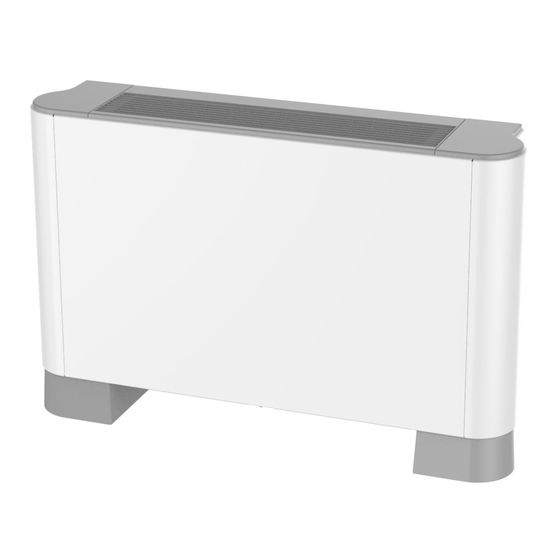
PRODUCT 1 Introduction Gree exposed fan coil units (FCUs), including cassette type, wall-mounted type, floor-ceiling type, and vertical exposed type, can be installed in various modes. They are of wide cooling capacity, complete functions, fashionable appearance, safe and reliable operation and other characteristics. Meanwhile, CE certification, Eurovent certification and other EU certification are available. -
Page 5: Lineup
Product 1.2 lineup 1.2.1 Vertical mounted exposed type Cooling Heating Power Type Model Product code capacity capacity Appearance supply (kW/ton) (kW/ton) FP-22LM/D-K EM51600300 1.4/0.40 2/0.57 FP-34LM/D-K EM51600280 1.9/0.54 2.3/0.65 FP-51LM/D-K EM51600290 2.8/0.80 3.4/0.97 FP-68LM/D-K EM51600250 3.2/0.91 3.8/1.08 FP-85LM/D-K EM51600270 4.25/1.21 4.9/1.39... - Page 6 Product Cooling Heating Power Type Model Product code capacity capacity Appearance supply (kW/ton) (kW/ton) FP-85XD/B-T EM520N0930 4.15/1.18 5.6/1.59 FP-102XD/B-T EM520N0910 5/1.42 6.5/1.85 FP-125XD/B-T EM520N0890 6/1.71 7.8/2.22 FP-140XD/B-T EM520N0870 8/2.27 9/2.56 FP-160XD/B-T EM520N0850 8.7/2.47 10/2.84 FP-180XD/B-T EM520N0830 9.5/2.7 11/3.13 FP-200XD/B-T EM520N0810 13/3.7 14.6/4.15 FP-68XDT/B-K...
-
Page 7: Cassette Type (Dc)
Product 1.2.3 Cassette type (DC) Cooling capacity Heating capacity (kW/ton) (kW/ton) Product Power Type Model Appearance code supply Others Others FPD-51XD/A-S EM520N1580 3.1/0.88 3.4/0.97 3.55/1.01 5.6/1.59 FPD-68XD/A-S EM520N1500 3.9/1.11 4.25/1.21 4/1.14 6.3/1.79 FPD-85XD/A-S EM520N1570 4.75/1.35 5.1/1.45 5.65/1.61 8.4/2.39 FPD-102XD/A-S EM520N1540 5.15/1.46 5.7/1.62 6.1/1.73 9/2.56 FPD-119XD/A-S EM520N1550 6.7/1.91 7.3/2.08... -
Page 8: Wall Mounted Type (Ac)
Product 1.2.5 Wall mounted type (AC) Cooling Product Air flow Power Type Model capacity Remarks code supply FP-34BA2/D-K(E) EM55002370 2/0.57 2.3/0.65 FP-51BA2/D-K(E) EM55002410 2.5/0.71 2.8/0.8 FP-68BA2/D-K(E) EM55002450 3.6/1.02 4.1/1.17 FP-85BA2/D-K(E) EM55002490 4/1.14 4.5/1.28 FP-34BA2/D-K EM55001810 2/0.57 2.7/0.77 220-240V 50Hz FP-51BA2/D-K EM55001820 2.5/0.71 3.2/0.91 FP-68BA2/D-K EM55001830 3.6/1.02 4.6/1.31... -
Page 9: Floor-Ceiling Type (Dc)
Product Cooling Product Air flow Power Type Model capacity Remarks code supply FP-34BA3/B-D EM55001760 2.1/0.6 3.15/0.9 FP-51BA3/B-D EM55001800 2.7/0.77 4.05/1.15 208-230V FP-68BA3/B-D EM55001770 3.6/1.02 5.4/1.54 60Hz FP-85BA3/B-D EM55001780 4.2/1.19 6.3/1.79 FP-102BA3/B-D EM55001790 5.4/1.54 8.5/2.42 FP-34BA4/D-K(E) EM55002390 2/0.57 2.3/0.65 Wall FP-51BA4/D-K(E) EM55002430 2.5/0.71 2.8/0.8 mounted FP-68BA4/D-K(E) EM55002470 3.6/1.02 4.1/1.17... -
Page 10: Floor-Ceiling Type (Ac)
Product 1.2.7 Floor-ceiling type (AC) Cooling capacity Heating capacity Power (kW/Ton) (kW/Ton) Type Model Product code Appearance supply Others Others FP-34ZD/B-K EM56000340 2.4/0.68 2.6/0.74 3/0.85 5/1.42 FP-51ZD/B-K EM56000330 2.65/0.75 2.9/0.82 3.5/1.00 5.3/1.51 FP-68ZD/B-K EM56000350 3.35/0.95 3.6/1.02 4.35/1.24 6.4/1.82 FP-85ZD/B-K EM56000460 3.4/0.97 3.65/1.04 4.4/1.25 6.5/1.85 B series floor-... -
Page 11: Specifications
Product 1.3 Specifications 1.3.1 Performance data (nominal conditions) Vertical mounted exposed type ◆ Model FP-22LM/D-K FP-34LM/D-K FP-51LM/D-K FP-68LM/D-K Type V-Ph-Hz 220-240VAC, 50Hz Power system Input High Air flow volume Medium Cooling 1400 1900 2800 3200 Capacity Heating 2000 2300 3400... - Page 12 Product Model FP-85LM/D-K FP-102LM/D-K FP-119LM/D-K Type V-Ph-Hz 220-240VAC, 50Hz Power system Input High 1000 1100 Air flow volume Medium Cooling 4250 5000 5300 Capacity Heating 4900 5900 6450 Cooling water flow 0.21 0.25 0.26 volume Heating water flow 0.26 0.28 volume Water system Cooling pressure...
- Page 13 Product Model FP-136LM/D-K FP-170LM/D-K FP-204LM/D-K Type V-Ph-Hz 220-240VAC, 50Hz Power system Input 1000 1118 High 1100 1700 1900 Air flow volume Medium 1275 1425 Cooling 5900 9200 10100 Capacity Heating 6800 10700 11500 Cooling water flow 0.28 0.44 0.48 volume Heating water flow 0.32 0.51...
- Page 14 Product Cassette type (AC) ◆ Model FP-85XD/B-T FP-102XD/B-T FP-125XD/B-T FP-140XD/B-T Type V-Ph-Hz 208-230VAC, 60Hz Power system Input High 1020 1130 1350 Air flow volume Medium 1100 1000 Cooling 4600 5400 6300 8000 Capacity Heating 7800 9000 10000 12000 Cooling water 0.22 0.26 0.38...
- Page 15 Product Model FP-160XD/B-T FP-180XD/B-T FP-200XD/B-T Type V-Ph-Hz 208-230VAC, 60Hz Power system Input 1059 1176 High 1550 1800 2000 Air flow volume Medium 1300 1400 1550 1150 1300 1250 Cooling 9000 10000 13000 Capacity Heating 14000 16000 19000 Cooling water 0.43 0.48 0.62 flow volume...
- Page 16 Product Model FP-85XD/B-T FP-102XD/B-T FP-125XD/B-T FP-140XD/B-T Type V-Ph-Hz 220-240VAC 50Hz Power system Input High 1020 1180 1400 Air flow volume Medium 1000 1250 1150 Cooling 4500 5000 6000 8000 Capacity Heating 5600 6500 7800 9000 Cooling water 0.21 0.24 0.29 0.38 flow volume Heating water...
- Page 17 Product Model FP-160XD/B-T FP-180XD/B-T FP-200XD/B-T Type V-Ph-Hz 220-240V~50Hz Power system Input 1059 1176 High 1550 1800 2000 1000 Air flow volume Medium 1400 1450 1700 1300 1350 1450 Cooling 8700 9500 13000 Capacity Heating 10000 11000 14600 Cooling water 0.42 0.45 0.62 flow volume...
- Page 18 Product Model FP-68XDT/B-K FP-85XDT/B-K Type V-Ph-Hz Power system Input High Air flow volume Medium Cooling 3500 4100 Capacity Heating 5800 6400 Cooling water flow 0.21 0.24 volume Heating water flow 0.17 0.19 volume Water system Cooling pressure 34.14 56.71 drop Heating pressure 76.44 86.08...
- Page 19 Product Model FP-102XDT/B-K FP-125XDT/B-K FP-140XDT/B-K Type V-Ph-Hz 220-240V~ 50Hz Power system Input High 1020 1250 1400 Air flow volume Medium 1108 1250 1014 1100 Cooling 5400 6000 6400 Capacity Heating 8000 9000 9500 Cooling water flow 0.27 0.29 volume Heating water flow 0.27 0.23 volume...
- Page 20 Product Model FP-180XDT/B-K FP-200XDT/B-K Type V-Ph-Hz 220-240VAC 50Hz Power system Input 1059 1177 High m3/h 1800 2000 1000 Air flow volume Medium m3/h 1525 1700 m3/h 1421 1500 Cooling 8000 9000 Capacity Heating 11500 12500 Cooling water flow 0.44 0.45 volume Heating water flow 0.36...
- Page 21 Product FP-68XDT/ FP-85XDT/ FP-125XDT/ FP-180XDT/ Model B-K(E) B-K(E) B-K(E) B-K(E) Type V-Ph-Hz 220-240VAC 50Hz Power system Input 1000 High 1250 1700 Air flow Medium volume 1108 1525 1014 1421 Cooling 3500 4500 6000 8000 Capacity Heating 5800 6800 9200 12000 Cooling water 0.21 0.24...
- Page 22 Product FP-85XD/ FP-102XD/ FP-125XD/ FP-140XD/ Model B-T(E) B-T(E) B-T(E) B-T(E) Type V-Ph-Hz 220-240VAC 50Hz Power system Input High 1090 1400 Air flow Medium volume 1160 1000 Cooling 4500 5000 6000 7400 Capacity Heating 5400 6100 6900 8400 Cooling water 0.22 0.24 0.29 0.35...
- Page 23 Product Model FP-160XD/B-T(E) FP-180XD/B-T(E) Type V-Ph-Hz 220-240VAC, 50Hz Power system Input High 1500 1640 Air flow volume Medium 1200 1360 1000 1200 Cooling 8400 9500 Capacity Heating 9000 10500 Cooling water 0.45 flow volume Heating water 0.43 0.49 flow volume Water system Cooling pressure drop...
- Page 24 Product Model FP-51XD/A-K FP-68XD/A-K FP-238XD/C-K Type V-Ph-Hz 220-240VAC, 50Hz Power system Input 1295 High 2200 1118 Air flow Medium volume 1900 1300 Cooling 2750 3400 12000 Capacity Heating 3400 3800 13000 Cooling water flow 0.13 0.18 0.57 volume Heating water flow 0.16 0.62 Water system...
- Page 25 Product type, dry bulb temperature: 20°C, wet bulb temperature: no more than 15°C, entering/leaving water temperature: 65°C/55°C (c) The sound level is tested under the semi-anechoic chamber and the actual value will change under different conditions. Testing conditions for models connecting to power at 60Hz: (a) Rated cooling conditions—dry/wet bulb temperature: 27°C/19.5°C, entering/leaving water temperature: 7°C/12°C.
- Page 26 Product FPD-51XD/ FPD-68XD/ FPD-85XD/ FPD-102XD/ FPD-119XD/ Model Water inlet & inch Rc3/4 Connection outlet Condensing water pipe size 25×2.5mm (OD×Wall thickness) drain Outline Body 570×570×260 840×840×200 dimension (W×D×H) Panel 620×620×65 950×950×65 Package Body 695×650×280 930×930×240 dimension (W×D×H) Panel 690×690×100 1030×1017×95 Body 16.5 16.5...
- Page 27 Product Model FPD-136XD/A-S FPD-170XD/A-S FPD-204XD/A-S FPD-238XD/A-S Cooling water 0.36 0.43 0.53 0.55 flow volume(EU) Heating water 0.41 0.58 flow volume(EU) Cooling pressure drop(EU) Heating pressure drop(EU) Cooling water Water flow volume(Non 0.39 0.46 0.57 system Heating water flow volume(Non 0.39 0.46 0.57 Cooling pressure...
- Page 28 Product 2. Testing conditions for models used in non-EU countries and regions (a) Rated cooling conditions—dry/wet bulb temperature: 27°C/19.5°C, entering/leaving water temperature: 7°C/12°C. (b) Rated heating conditions—dry bulb temperature: 21°C, entering water temperature: 60°C, the water flow is the same as that of the cooling condition. 3.
- Page 29 Product FPD-34BB4/A-K FPD-51BB4/A-K Model FPD-34BB6/A-K FPD-51BB6/A-K 20'GP (with panel) Loading quantity 40'GP (with panel) 40'HQ (with panel) Wired remote controller XE7A-17/E(M) Wireless remote controller YAP1F FPD-68BB4/A-K FPD-85BB4/A-K Model FPD-68BB6/A-K FPD-85BB6/A-K Type V-Ph-Hz 220-240V~ 50Hz Power system Input High Air flow volume Medium Cooling Capacity...
- Page 30 Product FPD-68BB4/A-K FPD-85BB4/A-K Model FPD-68BB6/A-K FPD-85BB6/A-K Wired remote controller XE7A-17/E(M) Wireless remote controller YAP1F...
- Page 31 Product A series wall mounted type (AC) ◆ FP-34BA2/D-K(E) FP-51BA2/D-K(E) Model FP-34BA3/D-K(E) FP-51BA3/D-K(E) FP-34BA4/D-K(E) FP-51BA4/D-K(E) Type V-Ph-Hz 220-240V~ 50Hz Power system Input High Air flow volume Medium Cooling 2000 2500 Capacity Heating 2300 2800 Cooling water flow 0.12 volume Heating water flow 0.11 0.13 volume...
- Page 32 Product FP-68BA2/D-K(E) FP-85BA2/D-K(E) Model FP-68BA3/D-K(E) FP-85BA3/D-K(E) FP-68BA4/D-K(E) FP-85BA4/D-K(E) Type V-Ph-Hz 220-240V~ 50Hz Power system Input High Air flow volume Medium Cooling 3600 4000 Capacity Heating 4100 4500 Cooling water flow 0.17 0.19 volume Heating water flow 0.21 volume Water system Cooling pressure drop Heating pressure...
- Page 33 Product FP-34BA2/D-K FP-51BA2/D-K FP-68BA2/D-K Model FP-34BA3/D-K FP-51BA3/D-K FP-68BA3/D-K FP-34BA4/D-K FP-51BA4/D-K FP-68BA4/D-K Type V-Ph-Hz 220-240V~ 50Hz Power system Input High Air flow volume Medium Cooling 2000 2500 3600 Capacity Heating 2700 3200 4600 Cooling water flow 0.12 0.17 volume Heating water flow 0.13 0.15 0.22...
- Page 34 Product FP-85BA2/D-K Model FP-85BA3/D-K FP-85BA4/D-K 220-240V~ 50Hz Type V-Ph-Hz Power system Input High Air flow volume Medium Cooling 4200 Capacity Heating 5400 Cooling water flow volume Heating water flow 0.26 volume Water system Cooling pressure drop Heating pressure drop Sound pressure level dB(A) Aluminum fin-copper tube Type...
- Page 35 Product FP-34BA2/B-D FP-51BA2/B-D FP-68BA2/B-D Model FP-34BA3/B-D FP-51BA3/B-D FP-68BA3/B-D Type V-Ph-Hz 208-230V~ 60Hz Power system Input High Air flow volume Medium Cooling 2100 2700 3600 Capacity Heating 3150 4050 5400 Cooling water flow 0.13 0.17 volume Heating water flow 0.15 0.19 0.26 volume Water system...
- Page 36 Product FP-85BA2/B-D FP-102BA2/B-D Model FP-85BA3/B-D FP-102BA3/B-D Type V-Ph-Hz 208-230V~ 60Hz Power system Input High 1000 Air flow volume Medium Cooling 4200 5400 Capacity Heating 6300 8500 Cooling water flow 0.26 volume Heating water flow volume Water system Cooling pressure drop Heating pressure drop Sound pressure level...
- Page 37 Product Model FP-34BA3/B-K FP-51BA3/B-K Type V-Ph-Hz 220-240V~ 50Hz Power system Input High Air flow volume Medium Cooling 1850 2650 Capacity Heating 2450 3050 Cooling water 0.09 0.13 flow volume Heating water 0.12 0.15 flow volume Water system Cooling pressure drop Heating pressure drop Sound pressure level...
- Page 38 Product Model FP-68BA3/B-K FP-85BA3/B-K Type V-Ph-Hz 220-240V~ 50Hz Power system Input High Air flow volume Medium Cooling 3500 4550 Capacity Heating 3850 4800 Cooling water 0.17 0.22 flow volume Heating water 0.18 0.23 flow volume Water system Cooling pressure drop Heating pressure drop Sound pressure level...
- Page 39 Product FP-51BWA2/A-K(E) FP-85BWA2/A-K(E) Model FP-51BWA3/A-K(E) FP-85BWA3/A-K(E) Type V-Ph-Hz 220-240V~ 50Hz Power system Input High Air flow volume Medium Cooling 1400 3100 Capacity Heating 2000 3300 Cooling water flow 0.07 0.15 volume Heating water flow 0.16 volume Water system Cooling pressure drop Heating pressure drop...
- Page 40 Product (c) The sound level is tested under the semi-anechoic chamber and the actual value will change under different conditions. Testing conditions for models connecting to power at 60Hz: (a) Rated cooling conditions—dry/wet bulb temperature: 27°C/19.5°C, entering/leaving water temperature: 7°C/12°C. (b) Rated heating conditions—dry bulb temperature: 21°C, entering water temperature: 60°C;...
- Page 41 Product FPD-34ZD/ FPD-51ZD/ FPD-68ZD/ FPD-85ZD/ FPD-102ZD/ Model 20'GP (with panel) Loading 40'GP (with panel) Quantity 40'HQ (with panel) Wireless remote controller YAP1F Wired remote controller XE7B-17/E(M) FPD-119ZD/ FPD-136ZD/ FPD-170ZD/ FPD-204ZD/ Model Code EM56000440 EM56000370 EM56000470 EM56000360 V-Ph- Type 220-240V~50/60Hz Power system Input 1000...
- Page 42 Product FPD-119ZD/ FPD-136ZD/ FPD-170ZD/ FPD-204ZD/ Model Package dimension(W×D×H) 1300×285×767 1666×285×767 Net weight Gross weight 20'GP (with panel) Loading 40'GP (with panel) Quantity 40'HQ (with panel) Wireless remote controller YAP1F Wired remote controller XE7B-17/E(M) Notes: 1. Testing conditions for models used in EU countries and regions (a) Rated cooling conditions—dry/wet bulb temperature: 27°C/19°C, entering/leaving water temperature: 7°C/12°C.
- Page 43 Product FP-34ZD/ FP-51ZD/ FP-68ZD/ FP-85ZD/ FP-102ZD/ Model Cooling water 0.12 0.13 0.16 0.16 0.25 flow volume(EU) Heating water 0.14 0.12 0.21 0.21 flow volume(EU) Cooling pressure drop(EU) Heating pressure drop(EU) Cooling water Water flow volume(Non 0.12 0.14 0.17 0.27 system Heating water flow volume(Non 0.12...
- Page 44 Product Model FP-119ZD/B-K FP-136ZD/B-K FP-170ZD/B-K FP-204ZD/B-K Cooling(EU) 5900 6000 9400 10000 Heating(EU) 7200 7300 11600 12500 Cooling(Non Capacity 6800 6900 9900 10500 Heating(Non 11400 11500 17400 19000 Cooling water 0.28 0.29 0.45 0.48 flow volume(EU) Heating water 0.34 0.35 0.55 0.59 flow volume(EU) Cooling...
-
Page 45: Outline Dimensions
The actual use changes due to changes of the environment. 1.3.2 Outline dimensions Vertical mounted exposed type ◆ Outlet pipe size Rc3/4 Inlet pipe size Rc3/4 Drain pipe size φ22 Unit: mm Model FP-22LM/D-K FP-34LM/D-K FP-51LM/D-K 1050 FP-68LM/D-K 1050 FP-85LM/D-K 1050 FP-102LM/D-K... - Page 46 Product Cassette type (AC) ◆ Entering water pipe Rc3/4 Leaving water pipe Rc3/4 Water outlet φ25 E (Gaps between hoisting screw rods) C (Indoor unit) B (Ceiling opening) A (Decorated surface boards) F (Thickness of the body)
- Page 47 Product Model FP-51XD/A-K FP-68XD/A-K FP-85XD/B-T FP-102XD/B-T FP-125XD/B-T FP-140XD/B-T FP-160XD/B-T FP-180XD/B-T Two-coil FP-200XD/B-T type FP-238XD/C-K 1040 FP-85XD/B-T(E) FP-102XD/B-T(E) FP-125XD/B-T(E) FP-140XD/B-T(E) FP-160XD/B-T(E) FP-180XD/B-T(E) FP-68XDT/B-K FP-85XDT/B-K FP-102XDT/B-K FP-125XDT/B-K FP-140XDT/B-K Four-coil type FP-180XDT/B-K FP-200XDT/B-K FP-68XDT/B-K(E) FP-85XDT/B-K(E) FP-125XDT/B-K(E) FP-180XDT/B-K(E)
- Page 48 Product A series cassette type (DC) ◆ Model FPD-51/68XD/A-S FPD-85/102/119XD/A-S FPD-136XD/A-S FPD-170/204XD/A-S FPD-238XD/A-S 1040 Wall mounted type (AC) ◆ Model Model FP-34BA2/D-K(E) FP-68BA2/D-K(E) FP-34BA3/D-K(E) FP-68BA3/D-K(E) FP-34BA4/D-K(E) FP-68BA4/D-K(E) FP-51BA2/D-K(E) FP-85BA2/D-K(E) FP-51BA3/D-K(E) FP-85BA3/D-K(E) FP-51BA4/D-K(E) FP-85BA4/D-K(E)
- Page 49 Product Model Model FP-34BA2/D-K FP-68BA2/D-K FP-34BA3/D-K FP-68BA3/D-K FP-34BA4/D-K FP-68BA4/D-K FP-51BA2/D-K FP-85BA2/D-K FP-51BA3/D-K FP-85BA3/D-K FP-51BA4/D-K FP-85BA4/D-K FP-68BA2/B-D FP-34BA2/B-D FP-68BA3/B-D FP-34BA3/B-D FP-85BA2/B-D FP-51BA2/B-D FP-85BA3/B-D FP-51BA3/B-D FP-102BA2/B-D FP-102BA3/B-D FP-34BA3/B-K FP-68BA3/B-K FP-51BA3/B-K FP-85BA3/B-K FP-51BWA2/A-K(E) FP-85BWA2/A-K(E) FP-51BWA3/A-K(E) FP-85BWA3/A-K(E) A series wall mounted type (DC) ◆ Model Model FPD-34BB4/A-K...
- Page 50 Product A series floor-ceiling type (DC)/B series floor-ceiling type (DC) ◆ Unit: mm Model FPD-34/51/68/85ZD/A-S FP-34/51/68/85ZD/B-K FPD-102/119/136ZD/A-S 1200 1142 FP-102/119/136ZD/B-K FPD-170/204ZD/A-S 1570 1512 FP-170170/204ZD/B-K...
-
Page 51: Exploded Views And Parts List
2 Exploded views and parts list 2.1 Vertical mounted exposed type The data below is just for reference. All specifications are subject to change by the manufacturer without prior notice. (1) FP-22LM/D-K, FP-34LM/D-K (list code: EM51600280) Name Quantity Display panel Cover... - Page 52 Product Name Quantity Cellular Centrifugal Fan Assy Right Side Plate Assy Closed Panel Propeller Housing Right Side Plate Centrifugal fan blade Propeller Housing Base Panel Connection Panel Cellular Assy Filter Assy Bar Clasp Support sub-assy Motor Motor Support Assy Base Cable cross loop Wire Clamp Insulated Gasket...
- Page 53 Product (2) FP-51LM/D-K, FP-68LM/D-K, FP-85LM/D-K (list code: EM51600250) Name Quantity Display panel Cover Grille Display panel Cover Displayer Box Base Deck Assy Cellular Surface-Cooler Assy Connection Panel Cellular Centrifugal Fan Assy Right Side Plate Assy Closed Panel Propeller Housing Right Side Plate Centrifugal fan blade...
- Page 54 Product Name Quantity Propeller Housing Base Filter Assy Panel Connection Panel Support sub-assy Bar Clasp Motor Cellular Assy Motor Support Assy Cable cross loop Wire Clamp Insulated Gasket Capacitance Terminal Board Terminal Board Cable cross loop Base Electric Box Cover Left Side Plate Left Side Plate Assy Cellular...
- Page 55 Product (3) FP-102LM/D-K, FP-119LM/D-K, FP-136LM/D-K (list code: EM51600310) Name Quantity Display panel Cover Grille Display panel Cover Displayer Box Base Deck Assy Cellular Surface-Cooler Assy Connection Panel Cellular Barrier Assy Right Side Plate Assy Closed Panel Propeller Housing Right Side Plate...
- Page 56 Product Name Quantity Centrifugal fan blade Propeller Housing Base Filter Assy Connection Panel Panel Support sub-assy Bar Clasp Motor Motor Support Cellular Assy Cable cross loop Wire Clamp Insulated Gasket Capacitance Terminal Board Terminal Board Cable cross loop Base Electric Box Cover Left Side Plate Left Side Plate Assy Cellular...
- Page 57 Product (4) FP-170LM/D-K (list code: EM51600320) Name Quantity Display Board Cover Front Grill Foam Surface-Cooler Assy Display Box Right Side Plate Connection Board Foam Rear Case Right Side Plate Sub-Assy Propeller Housing(Lower) Propeller Housing(Upper)
- Page 58 Product Name Quantity Centrifugal Fan Foam Sub- Assy Air Outlet Assy Front Panel Motor Support Fan Motor Connection Sheet Sub-Assy Connection Board Connection Sheet Sub-Assy Filter Sub-Assy Rear Case Left Side Plate Sub-Assy Cable Cross Loop Left Side Plate Electric Box Cover Wire Clamp Capacitor CBB61 Display Board Cover...
- Page 59 Product (5) FP-204LM/D-K (list code: EM51600340) Name Quantity Display Board Cover Front Grill Foam Surface-Cooler Assy Display Box Right Side Plate Connection Board Foam Rear Case Right Side Plate Sub-Assy Propeller Housing(Lower) Propeller Housing(Upper) Centrifugal Fan Foam Sub- Assy Air Outlet Assy...
- Page 60 Product Name Quantity Front Panel Motor Support Fan Motor Connection Sheet Sub-Assy Connection Board Connection Sheet Sub-Assy Filter Sub-Assy Rear Case Left Side Plate Sub-Assy Cable Cross Loop Left Side Plate Electric Box Cover Wire Clamp Capacitor CBB61 Display Board Cover Insulation Gasket Terminal Board Terminal Board...
-
Page 61: Cassette Type (Ac)
Product 2.2 Cassette type (AC) (1) FP-85XD/B-T, FP-102XD/B-T, FP-125XD/B-T, FP-140XD/B-T, FP-160XD/B-T, FP-180XD/B-T, FP- 200XD/B-T, FP-85XD/B-T(E), FP-102XD/B-T(E), FP-125XD/B-T(E), FP-140XD/B-T(E), FP-160XD/ B-T(E), FP-180XD/B-T(E) - Page 62 Product Name Quantity Tube-exit Plate Body Fixing Plate Front Side Plate Left Side Plate Base Plate Rear Side Plate Bottom Foam Motor Gasket Bolt Motor Support Motor Centrifugal Fan Connected Board (Evaporator) Cable-cross Loop Heat exchanger Water Tray Flow-guide Loop Electric Box asm Electric Box Wire Clamp...
- Page 63 Product (2) FP-68XDT/B-K, FP-68XDT/B-K(E), FP-85XDT/B-K, FP-85XDT/B-K(E), FP-102XDT/B-K, FP- 125XDT/B-K, FP-125XDT/B-K(E), FP-140XDT/B-K, FP-180XDT/B-K, FP-180XDT/B-K(E), FP- 200XDT/B-K...
- Page 64 Product Name Quantity Tube Exit Plate Assy Body Fixing Plate Front Side Plate Left Side Plate Base Plate Rear Side Plate Bottom Foam Motor Gasket Motor Support Motor Centifugal Fan Evap Connection Deflation Valve Valve chest (air release valve) Valve chest (air release valve) Water Tray Flow-guide Loop Electric Box asm...
- Page 65 Product (3) FP-51XD/A-K, FP-68XD/A-K Name Quantity Rear Grill Fan Motor Water Tray Assy Water Pump Supporter Liquid Level Switch...
- Page 66 Product Name Quantity Pump Drainpipe Water Pump Assy Right Side Plate Sub-Assy Bottom Foam Assy Base Plate Assy Body Installing Support Left Side Plate Sub-Assy Electric Box Assy Terminal Board Breadboard Holder Main Board Capacitor CBB61 Transformer Front Side Plate Sub-Assy Drain Hose Sub-Assy Room Sensor Temperature Sensor...
-
Page 67: A Series Cassette Type (Dc)
Product 2.3 A series cassette type (DC) (1) FPD-51XD/A-S, FPD-68XD/A-S Name Quantity Shell Assy Seat Board Sub-Assy Side Plate Side Plate Side Plate Side Plate Brushless DC Motor Centifugal Fan Terminal Board Main Board Jumper Mounting Rack Sub-Assy Connection Sheet Sub-Assy Drain Pipe Water Pump Liquid Level Switch... - Page 68 Product Name Quantity Flow Guide Loop Temperature Sensor Support (2) FPD-85XD/A-S, FPD-102XD/A-S, FPD-119XD/A-S, FPD-136XD/A-S, FPD-170XD/A-S, FPD- 204XD/A-S Name Quantity Shell Assy Seat Board Sub-Assy Side Plate Side Plate Side Plate Side Plate Brushless DC Motor Centifugal Fan Terminal Board Main Board Jumper Mounting Rack Sub-Assy Connection Sheet Sub-Assy...
- Page 69 Product Name Quantity Liquid Level Switch Sealplate Water Tray Assy Flow Guide Loop Temperature Sensor Support (3) FPD-238XD/A-S Name Quantity Shell Assy Seat Board Sub-Assy Rear Side Plate Right and Left Side Plate Brushless DC Motor Centrifugal Fan Fan Fixer Terminal Board Terminal Board Main Board...
-
Page 70: Wall Mounted Type (Dc)
Product Water Level Switch Electric Box Cover Plate Water Tray Sub-Assy Water Pump Pump Gasket 2 Pump Gasket 1 Rubber Base Water Pump Assy Drainage Hose(Water Pump) Diversion Circle The above parameters are for reference only. The specific parameters shall be subject to the actual objects. - Page 71 Product Name Quantity Rear Case assy Stainless steel clasp Sensor Insert Shield Cover of Electric Box Cover 2 Electric Box Cover2 Shield Cover of Electric Box Cover Display Board Terminal Board Cable Clamp 2 Main Board Electric Box Drainage Hose Remote Controller Power Cord Temperature Sensor...
- Page 72 Product (2) FPD-85BB4/A-K, FPD-85BB6/A-K Name Quantity Wall Mounting Frame Rear Case Stainless steel clasp Sensor Insert Shield Cover of Electric Box Cover 2 Electric Box Cover2 Shield Cover of Electric Box Cover Display Board Terminal Board Cable Clamp 2 Main Board Electric Box Crank Stepping Motor...
- Page 73 Product Name Quantity Remote Controller Drainage Hose Rubber Plug (Water Tray) Power Cord Temperature Sensor Temperature Sensor Fan Motor Air relief valve core Surface-Cooler Assy Front Case Assy Front Panel Filter Sub-Assy Cross Flow Fan Air Louver(Manual) Guide Louver Helicoid Tongue Axile Bush Left Axile Bush Evaporator Support...
-
Page 74: Wall Mounted Type (Ac)
Product 2.5 Wall mounted type (AC) (1) FP-34BA2/D-K(E), FP-34BA3/D-K(E), FP-34BA4/D-K(E), FP-51BA2/D-K(E), FP-51BA3/D-K(E), FP- 51BA4/D-K(E), FP-34BA2/D-K, FP-34BA3/D-K, FP-34BA4/D-K, FP-51BA2/D-K, FP-51BA3/D-K, FP-51BA4/D-K, FP-34BB3/A-K(E), FP-51BB3/A-K(E), FP-34BA2/B-D, FP-34BA3/B-D, FP-51BA2/ B-D, FP-51BA3/B-D Name Quantity Wall-Mounting Frame Rear Case Evaporator Assy Evaporator Support Cross Flow Fan... - Page 75 Product Name Quantity Ring of Bearing Bearing cushion rubber base Volute tongue Left Axile Bush Crank Axile Bush Swing Louver1 Swing Louver2 Front Case Filter Remote Control Decorate Piece Display Board Front Panel Screw Cover Guide Louver Wire Clamp Rear Clamp Motor MP24AA Motor Clamp Motor...
- Page 76 Product Name Quantity Front Panel Assy Filter Sub-Assy Front Case Screw Cover Display Board Rubber Plug (Water Tray) Evaporator Assy Cross Flow Fan Ring of Bearing Rear Case Assy Wall Mounting Frame Helicoid tongue Air Louver 1 Axile Bush Left Axile Bush Guide Louver crank Step Motor...
- Page 77 Product Name Quantity Air Louver 2 Drainage hose Pipe Clamp Fan Motor Motor Press Plate Electric Box Main Board Transformer Terminal Board Electric Box Cover1 Shield cover of Electric Box Electric Box Cover2 Tube Sensor Ambient Temperature Sensor Remote Controller Power Cord Jumping Connector...
- Page 78 Product (3) FP-34BA3/B-K, FP-51BA3/B-K Name Quantity Wall-Mounting Frame Rear Case Surface-Cooler Assy...
- Page 79 Product Name Quantity Evaporator Support Cross Flow Fan Ring of Bearing Bearing cushion rubber base Volute Tongue Left Axile Bush Crank Axile Bush Swing Louver1 Swing Louver2 Front Case Filter Assy Decorate Piece Front Panel Guide Louver Screw Cover Wire Clamp Rear Clamp Stepping Motor Motor Clamp...
- Page 80 Product (4) FP-68BA3/B-K, FP-85BA3/B-K Name Quantity Front Panel Assy Filter Sub-Assy Front Case Screw Cover Rubber Plug (Water Tray) Surface Cooler Assy Cross Flow Fan Ring of Bearing Rear Case assy Wall Mounting Frame Volute tongue Air Louver 1 Axile Bush Left Axile Bush Guide Louver Crank...
- Page 81 Product Name Quantity Drainage hose Rear Clamp Motor Motor Press Plate Electric Box Capacitor Installation Supporting Frame Terminal Board Electric Box Cover 1 Shield cover of Electric Box Electric Box Cover 2 Electric Box Assy Evaporator Angular Pipe Connection Assembly Blow Molding Drainage Pipe...
- Page 82 Product (5) FP-51BWA2/A-K(E), FP-51BWA3/A-K(E) Name Quantity Wall-Mounting Frame Rear Case Evaporator Assy Evaporator Support Cross Flow Fan Ring of Bearing Bearing cushion rubber base Volute tongue...
- Page 83 Product Name Quantity Left Axile Bush Crank Axile Bush Swing Louver1 Swing Louver2 Front Case Filter Remote Control Decorate Piece Display Board Front Panel Screw Cover Guide Louver Wire Clamp Rear Clamp Motor MP24AA Motor Clamp Motor Electric Box Cover 1 Covering Plate2 Terminal Board Electric Box...
- Page 84 Product (6) FP-85BWA2/A-K(E), FP-85BWA3/A-K(E) Name Quantity Front Panel Assy Filter Sub-Assy Front Case Screw Cover Display Board Rubber Plug (Water Tray) Evaporator Assy Cross Flow Fan Ring of Bearing Rear Case Assy Wall Mounting Frame Helicoid tongue Air Louver 1 Axile Bush Left Axile Bush Guide Louver...
- Page 85 Product Name Quantity Pipe Clamp Fan Motor Motor Press Plate Electric Box Main Board Transformer Terminal Board Electric Box Cover1 Shield cover of Electric Box Electric Box Cover2 Tube Sensor Ambient Temperature Sensor Remote Controller Power Cord Note: The data in the table above is just for reference. We reserve the right to change design and construction specifications at any time without notice.
-
Page 86: A Series Floor-Ceiling Type (Dc)
Product 2.6 A series floor-ceiling type (DC) (1) FPD-34ZD/A-S, FPD-51ZD/A-S, FPD-68ZD/A-S, FPD-85ZD/A-S Name Quantity FrontGrill TopCover GuideLouver DisplayBoardAssy DrainagePipeSub-assy WaterTray PropellerHousing(Upper) CentifugalFan Brushless DC Motor FrontPanel Surface-CoolerAssy PropellerHousing(Lower) - Page 87 Product Name Quantity TemperatureSensor TemperatureSensor RearSidePlateSub-Assy BasePlateAssy ElectricBoxSub-Assy MainBoard TerminalBoard ElectricBoxCover LeftSidePlate (2) PD-102ZD/A-S, FPD-119ZD/A-S, FPD-136ZD/A-S Name Quantity Front Grill Front Grill Filter Sub-Assy Water Tray Assy Top Cover...
- Page 88 Product Name Quantity Drainage Pipe Sub-assy Water Tray Swing Lever Air Louver Support Right Side Plate Installation Supporting Frame(right) Cover Plate(Inlet and outlet Pipe) Right Side Plate Temperature Sensor Surface-Cooler Assy Mounting Rack Sub-Assy Front Panel Guide Louver Rotating Shaft 3 Mounting Rack Sub-Assy Display Board Assy Display Board...
- Page 89 Product (3) FPD-170ZD/A-S, FPD-204ZD/A-S Name Quantity Base Plate Assy Seat Board Sub-Assy Cover Plate(Inlet and outlet Pipe) Connection Sheet Display Board Assy Membrane Display Board Stepping Motor Mounting Rack Sub-Assy Guide Louver Rotating Shaft 3 Front Panel AXILE BUSH Mounting Rack Sub-Assy...
- Page 90 Product Name Quantity Surface-Cooler Assy Temperature Sensor Right Side Plate Cover Plate(Inlet and outlet Pipe) Installation Supporting Frame(right) Right Side Plate Water Tray Assy Support Air Louver Swing Lever Water Tray Drainage Pipe Sub-assy Top Cover Front Grill Filter Sub-Assy Front Grill Temperature Sensor Rear Side Plate Sub-Assy...
-
Page 91: B Series Floor-Ceiling Type (Ac)
Product 2.7 B series floor-ceiling type (AC) (1) FP-34ZD/B-K, FP-51ZD/B-K, FP-68ZD/B-K, FP-85ZD/B-K Name Quantity FrontGrill TopCover GuideLouver DisplayBoardAssy DrainagePipeSub-assy WaterTray PropellerHousing(Upper) CentifugalFan FanMotor FrontPanel... - Page 92 Product Name Quantity Surface-CoolerAssy PropellerHousing(Lower) TemperatureSensor TemperatureSensor RearSidePlateSub-Assy BasePlateAssy ElectricBoxAssy ElectricBoxSub-Assy MainBoard TerminalBoard TerminalBoard ElectricBoxCover LeftSidePlate (2) FP-102ZD/B-K, FP-119ZD/B-K, FP-136ZD/B-K...
- Page 93 Product Name Quantity Front Panel Front Grill Guide Louver Top Cover Drainage Pipe Sub-assy Display Board Display Board Assy Water Tray Assy Propeller Housing(Upper) Centifugal Fan Stepping Motor Roller Wheel Temperature Sensor Bearing Holder Sub-assy Propeller Housing(Lower) Surface-Cooler Assy Right Side Plate Rear Side Plate Sub-Assy Seat Board Sub-Assy Connection Sheet...
- Page 94 Product (3) FP-170ZD/B-K, FP-204ZD/B-K Name Quantity Front Grill Top Cover Guide Louver Drainage Pipe Sub-assy Display Board Assy Water Tray Assy Propeller Housing(Upper) Roller Wheel Centifugal Fan Joint Slack Fan Motor Propeller Housing(Lower) Clapboard Sub-Assy Support Of Motor Bearing Bearing Holder Sub-assy Front Panel...
- Page 95 Product Name Quantity Surface-Cooler Assy Rear Side Plate Sub-Assy Seat Board Sub-Assy Connection Sheet Temperature Sensor Temperature Sensor Electric Box Assy Electric Box Sub-Assy Main Board Terminal Board Terminal Board Capacitor Electric Box Cover Left Side Plate The above parameters are for reference only. The specific parameters shall be subject to the actual objects.
-
Page 96: Unit Installation
Unit Installation UNIT INSTALLATION 1 Precautions for engineering work (1) The unit should be installed in accordance with instructions covered in the user’s manual and make sure enough maintenance space is reserved around the unit. The air inlet and outlet should be far away from obstacles, so that air flow can go through everywhere of the room. -
Page 97: Tools
Unit Installation 2 Tools Level meter Measuring tape Screw driver Impact drill Pipe pliers Drill head Electric drill Electroprobe Inner hexagon Torque wrench Open-end wrench Soldering appliance spanner Pipe pliers Pipe cutter Pipe expander Pipe bender Moreover, it is necessary to prepare commonly accessible tools including pipe pliers, screw drivers, rubber pads, rubber hammers, scissors, spanners, level bars, measuring tape, angle square, glue guns, brushes, ladders, pulleys. -
Page 98: Installation
3.2 Unit installation 3.2.1 Vertical mounted exposed type Drill four holes on the wall accordance with the piture and the table below. Suspension hole Suspension hole Unit: mm Model α β FP-22LM/D-K FP-34LM/D-K FP-51LM/D-K FP-68LM/D-K FP-85LM/D-K FP-102LM/D-K FP-119LM/D-K 1010 FP-136LM/D-K... - Page 99 Unit Installation Insert user-provided M10 expansion bolts into the holes on the wall and fix them as shown in the picture below. Expansion bolt Open the cover. Loosen three screws and lift the decorated panels (on left or right side) 1cm above and remove them in a horizontal way.
-
Page 100: Cassette Type
Unit Installation ≥60cm ≥60cm ≥60cm ≥60cm ≥10cm ≥100cm ≥100cm Vertical-mounted Wall-mounted 3.2.2 Cassette type Hanging on the ceiling ◆ (1) Hole drilling and bolt installation 1) Firstly, place the cardboard template at the installation location and drill four holes as per the hole site at the cardboard template. - Page 101 Unit Installation (7) Remove the cardboard template. Screw (supplied on site) Washer (attached) Insert Hoisting hanger Locating plate Tighten two screws (tighten the washer) (tighten the hoisting hanger) Fix one corner of the drain channel with the screw. Center of the ceiling Cardboard (attached) for installation opening Water leve l...
- Page 102 Unit Installation Hanger Connector Piping position Swing motor Sealing material Unit Ceiling 5~8m ⑤ Air outlet Panel Precautions ◆ Improper screwing of the screws may cause the troubles. Air leak Air leak from ceiling Contamination dew condensation,dew dripping If gap is still left between the ceiling and the panel after screwing the screws, readjust the height of the unit body.
- Page 103 Unit Installation Adjustment of the indoor unit body from the holes in the corner of the panel is possible if the indooor unit is kept leveled and the drainage pipe piping etc is unaffectecd. No gap is allowed No gap should be left between the ceiling and the panel. Connect the joints for the conductors of swing motors (at two positions).
-
Page 104: Wall Mounted Type
Unit Installation 3.2.3 Wall mounted type Clearance ◆ structures. 50cm Installation of the rear panel ◆ (1) Always mount the rear panel horizontally. Due to the water tray of the unit has been adopted the both-way drainage design, the outlet of water tray should be adjusted slightly down when installing, that is to take the outlet of the water tray as the center of a circle, the included angle between the evaporator and level should be 0 or more, that is good for condensing water drainage. -
Page 105: Floor-Ceiling Type
Unit Installation 3.2.4 Floor-ceiling type Installation instructions ◆ (1) Use a cardboard to locate the positions of brackets. Then the cardboard can be removed. (2) Insert the expansion bolt into the hole and hammer at it. Expansion bolt Mounting cardboard (3) Dispatch the left and right panels. -
Page 106: Installation Of Water Pipes
Unit Installation Clearance ◆ Make sure that enough service space is preserved. (1) Floor standing mounted type Unit: mm Ceiling Ceiling Floor Floor (2) Ceiling mounted type Unit: mm Ceiling Ceiling Floor Floor 3.3 Installation of water pipes Threaded connection ◆... - Page 107 Unit Installation Pipe joint connecting ◆ (1) Align the center of the piping pipe with the relevant valve. (2) Place the nut, spring washer, washer, O-ring cross the pipe sequentially, and keep them tightly close to each other with a distance of 6-7mm from the O-ring to the pipe end. (3) Screw in the pipe nut by hand and then tighten the nut with spanner.
-
Page 108: Installation Of Drain Pipes
Unit Installation 3.4 Installation of drain pipes Precautions ◆ (1) The drain pipe should be as short as possible, with at least an inclination degree of 1%~2%, so that the condensate can be drained out smoothly. If the inclination degree fails to meet this requirement, a raising pipe is required. -
Page 109: Installation Of Water Valves
Unit Installation Precautions for the raising pipe ◆ (1) The height of the raising pipe should be less than 280mm. (2) The raising pipe should be at a right angle to the unit and keep a distance with the unit within 300mm. - Page 110 Unit Installation (3) After the connector, the water valve and the water pipes have been finished, you may start the water pump and see if they leak or not. (4) Insulate the water valve and the pipe with sponge. Electric valve Unit Outlet pipe Power cord...
-
Page 111: Electrical Connection
Unit Installation Do not cover fully the valve with the insulation sponge; otherwise it would lead to Insulation sponge poor heat radiation and even fire hazards. (2) There are direct pass and bypass for the water valve and they can be selected based on actual conditions. - Page 112 Unit Installation valve cables with clamps. (2) When matching the optional accessories, connect the signal line through the rubber ring to the terminal board of the controller. After connection, be sure to secure the cable with clamps. (3) When connecting the optional cable, power must be cut off first, and then power on after connection has been finished.
-
Page 113: External Wiring Diagram
Unit Installation 4.3 External wiring diagram The wiring diagram is for reference, and the actual wiring is subject to the diagram posted on the unit. 4.3.1 Vertical mounted exposed type... -
Page 114: Cassette Type (Ac)
Unit Installation 4.3.2 Cassette type (AC) (1) FP-85XD/B-T, FP-102XD/B-T, FP-125XD/B-T, FP-140XD/B-T, FP-160XD/B-T, FP-180XD/B-T, FP- 200XD/B-T, FP-85XD/B-T(E), FP-102XD/B-T(E), FP-125XD/B-T(E), FP-140XD/B-T(E), FP-160XD/ B-T(E), FP-180XD/B-T(E) (electric specification: 50Hz/60Hz) - Page 115 Unit Installation (2) FP-68XDT/B-K, FP-68XDT/B-K(E), FP-85XDT/B-K, FP-85XDT/B-K(E), FP-102XDT/B-K, FP- 125XDT/B-K, FP-125XDT/B-K(E), FP-140XDT/B-K, FP-180XDT/B-K, FP-180XDT/B-K(E), FP- 200XDT/B-K...
- Page 116 Unit Installation (3) FP-51/68XD/A-K...
- Page 117 Unit Installation (4) FP-238XD/C-K...
-
Page 118: A Series Cassette Type (Dc)
Unit Installation 4.3.3 A series cassette type (DC) (1) FPD-51XD/A-S, FPD-68XD/A-S... - Page 119 Unit Installation (2) FPD-85XD/A-S, FPD-102XD/A-S, FPD-119XD/A-S, FPD-136XD/A-S, FPD-170XD/A-S, FPD- 204XD/A-S...
- Page 120 Unit Installation (3) FPD-238XD/A-S...
-
Page 121: Wall-Mounted Type (Dc)
Unit Installation 4.3.4 Wall-mounted type (DC) (1) FPD-34BB4/A-K, FPD-51BB4/A-K, FPD-68BB4/A-K, FPD-85BB4/A-K, FPD-34BB6/A-K, FPD- 51BB6/A-K, FPD-68BB6/A-K, FPD-85BB6/A-K... -
Page 122: Wall-Mounted Type (Ac)
Unit Installation 4.3.5 Wall-mounted type (AC) (1) FP-34BA2/D-K(E), FP-51BA2/D-K(E), FP-68BA2/D-K(E), FP-85BA2/D-K(E), FP-34BA3/D-K(E), FP- 51BA3/D-K(E), FP-68BA3/D-K(E), FP-85BA3/D-K(E), FP-34BA4/D-K(E), FP-51BA4/D-K(E), FP- 68BA4/D-K(E), FP-85BA4/D-K(E), FP-34BA2/D-K, FP-51BA2/D-K, FP-68BA2/D-K, FP-85BA2/D-K, FP-34BA3/D-K, FP-51BA3/D-K, FP-68BA3/D-K, FP-85BA3/D-K, FP-34BA4/D-K, FP-51BA4/D-K, FP-68BA4/D-K, FP-85BA4/D-K, FP-34BA2/B-D, FP-51BA2/B-D, FP-68BA2/B-D, FP-85BA2/B-D, FP-102BA2/B-D, FP-34BA3/B-D, FP-51BA3/B-D, FP-68BA3/B-D, FP-85BA3/B-D, FP-102BA3/B-D... - Page 123 Unit Installation (2) FP-34BA3/B-K, FP-51BA3/B-K, FP-68BA3/B-K, FP-85BA3/B-K (3) FP-51BWA2/A-K(E)
- Page 124 Unit Installation (4) FP-85BWA2/A-K(E) (5) FP-51BWA3/A-K(E), FP-85BWA3/A-K(E)
-
Page 125: A Series Floor-Ceiling Type (Dc)
Unit Installation 4.3.6 A series floor-ceiling type (DC) (1) FPD-34ZD/A-S, FPD-51ZD/A-S, FPD-68ZD/A-S, FPD-85ZD/A-S, FPD-102ZD/A-S, FPD-136ZD/A-S, FPD-170ZD/A-S, FPD-204ZD/A-S... -
Page 126: A Series Floor-Ceiling Type (Ac)
Unit Installation 4.3.7 A series floor-ceiling type (AC) (1) FP-34ZD/B-K, FP-51ZD/B-K, FP-68ZD/B-K, FP-85ZD/B-K, FP-102ZD/B-K, FP-136ZD/B-K, FP- 170ZD/B-K, FP-204ZD/B-K... -
Page 127: One-To-More Control
Unit Installation 4.3.8 One-to-more Control Up to 32 FCUs can be controlled at the same time by a wired controller. Notes: (1) Refer to the circuit diagram for specific wiring. (2) One-to-more control requires a wired controller which is able to control all FCUs at the same time but cannot control a separate one alone. - Page 128 Unit Installation (3) Remove the wire clip,pull out the WiFi connection wire from the electric box and then connect it with the port in WiFi module. WiFi module WiFi connection wire NOTICE:the WiFi connection wire shall go through the wire groove.otherwise thelectric box cannot be closed.
- Page 129 Unit Installation FPD-238XD model After the WiFi module connecting the wires from the electric box, use the cable tie to bind the module and other cables together at the wire hole as shown in below figure. The excess cable should be neatly arranged and placed in the idle space inside the electric box.
-
Page 130: Dip Setting
Unit Installation 4.3.11 DIP setting Function DIP setting ◆ “1”: it is used to determine whether to stop the fan when the ambient temperature reaches the set temperature point. When it is set to the "ON side", it means that the fan will be stopped when the ambient temperature reaches the set point;... - Page 131 Unit Installation Note: One-to-more control function can control 1~32 units. When there are more than 2 units in control, each unit must be set to a different address, otherwise the unit will operate abnormally.
-
Page 132: Diagnostics
Unit Installation Address DIP setting (rotary type) ◆ Up to 10 settings are available, that is, the arrow pointing to different numbers represents different addresses (a total of 10 numbers from 0 to 9). Note: One-to-more control function can control 1~10 units. When there are more than 2 units in control, each unit must be set to a different address, otherwise the unit will operate abnormally. -
Page 133: Maintenance
Maintenance MAINTENANCE 1 Servicing (1) Power supply must be cut off before any maintenance. (2) Maintenance must be operated by qualified servicemen. 1.1 Vertical mounted exposed type Step Picture Work instruction (1) Detach the filter. Pull up the filter. • Use the dust collector or water to clean the filter screen. - Page 134 Maintenance Step Picture Work instruction • Open up the two display top covers. • Take out the screws from the left, right and top of (3)Take off decorated the unit. panels. • Lift up its decorated panels (on left or right side) and remove them in a horizon direction.
- Page 135 Maintenance Step Picture Work instruction Unscrew the grille and move (6) Take off the grille. it towards right and then up. (7) Detach the front Take out the screws from panel. the front panel. (8) Detach the volute Press clasps hard to take casing.
-
Page 136: Cassette Type (Ac)
Maintenance Step Picture Work instruction Use an inner hexagonal (9) Detach fan blades. spanner to unscrew fan blades from the motor. • Unscrew the electric box cover. • Take out connecting tabs between terminal blocks and capacitors. • Cut off fixing clamps to (10) Detach wires. - Page 137 Maintenance Step Picture Work instruction Use the dust collector or water to clean the filter screen. When the filter screen is quite dirty, warm (less than 45°C) detergent solution can be used. Then, dry it in the shade. (3) Clean the filter Notes: screen.
- Page 138 Maintenance Step Picture Work instruction Take out two screws from the electric box and then (7) Detach the disconnect each wiring electrical box. terminals, after that take the electric box out upward. Screw Flow guide loop Unscrew the flow-guide (8) Detach the flow- loop and then turn it counter guide loop.
- Page 139 Maintenance Step Picture Work instruction Screw • Unscrew the mounting plate and take it out. Mounting plate Baffle • Unscrew the baffle of the Screw pipe outlet, and then press it downward to pull out the buckles on both side, after that, take the baffle away.
-
Page 140: A Series Cassette Type (Dc)
Maintenance 1.3 A series cassette type (DC) Step Picture Work instruction (1) Take the screws out Remove the screw and pull the of the grille. buckle to open the panel. Pull the filter screen down wards (2) Remove the filter to make it away from the buckles screen. - Page 141 Maintenance Step Picture Work instruction • Turn off the power supply of indoor unit. • Push the 4 corner plates in (4) Remove the front the directions shown by the panel. arrows. • Loosen the screws and remove the front panel. (5) Remove the cover •...
- Page 142 Maintenance Step Picture Work instruction • Loosen the screws in the 4 (6) Remove the water corners and then remove the tray. water tray. • Use a screwdriver to remove (7) Remove the fan. the clamping band of motor. Then remove the fan.
- Page 143 Maintenance Step Picture Work instruction • Use a screwdriver to unscrew (8) Remove motor. the 4 screws of motor. Then remove the motor. • Remove the motor from motor support and then (9) Replace and install replace with a new motor. the motor.
-
Page 144: A Series Wall Mounted Type (Dc)
Maintenance Step Picture Work instruction • Direct the hole of fan to the motor shaft and then mount (10) Install the fan. on the fan. • Tighten the clamping band of motor with a wrench. • Direct the 4 corners of water tray to the 4 corners of the unit and then press them. - Page 145 Maintenance Step Picture Work instruction • Use the dust collector or water to clean the filter screen. When the filter screen is quite dirty, warm (less than 45°C) detergent solution can be used. Then, dry it in the shade. (2) Clean the filter Notes: screen.
- Page 146 Maintenance Step Picture Work instruction Screws and the screw cover • Open the screw cover and loosen the set (3) Remove the screws. inner panel. • Unscrew the light panel and the inner panel. The light panel and screws Clasps •...
- Page 147 Maintenance Step Picture Work instruction Unscrew the electric box (5) Remove the and pull it in the direction electric box. of the arrow. (6) Remove the Unscrew the cooling coil cooling coil. and take it off. • Unscrew plates and clamps that fix motors (7) Remove the to take them apart.
-
Page 148: A Series Floor-Ceiling Type (Dc)/B Series Floor-Ceiling Type Type (Ac)
Maintenance Step Picture Work instruction Take off the clasp in the middle and slightly bend (9) Remove the the swing louver to take swing louver. out the other clasps on both sides of the louver. Clasps 1.5 A series floor-ceiling type (DC)/B series floor-ceiling type type (AC) Step Picture Work instruction... - Page 149 Maintenance Step Picture Work instruction • Use a screwdriver to loosen the screws, as shown in the (3) Remove the left picture. Then pull the and right panels. right and left panels upward(Lines in the picture indicate the positions of screws) •...
- Page 150 Maintenance Step Picture Work instruction • Twist off the 6 screws of the evaporator, 3 screws of the (7) Remove plate board of water the evaporator releasing flume, and assembly. 2 screws of the water tray. Then remove the evaporator. ●First remove the display (8) Remove the panel, next the bracket...
- Page 151 Maintenance Step Picture Work instruction ●Loosen the 2 screws of the motor securing (12) Remove the clip. Remove the motor motor. securing clip and its assembly.
- Page 152 Add: West Jinji Rd, Qianshan, Zhuhai,Guangdong, China, 519070 Tel: (+86-756) 8522218 Fax: (+86-756) 8669426 E-mail: global@cn.gree.com www.gree.com For continuous improvement in the products, Gree reserves the right to modify the product specification and appearance in this manual without notice and without incurring any obligation. JF00304523...
Need help?
Do you have a question about the FP-22LM/D-K and is the answer not in the manual?
Questions and answers