Gree FP-85XD/B-T Owner's Manual
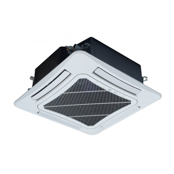
Cassette type fan coil unit
Hide thumbs
Also See for FP-85XD/B-T:
- Service manual (152 pages) ,
- User manual (28 pages) ,
- Service manual (70 pages)
Table of Contents
Advertisement
Change for life
Thank you for choosing commercial or household air conditioners.
Please read this Owner's Manual carefully before operation and retain it for
future reference.
If you have lost the Owner's Manual, please contact the local agent or visit www.
gree.com or send an email to global@gree.com.cn for the electronic version.
Cassette Type Fan Coil Unit
Owner's Manual(Original lnstructions)
Commercial or Household Air Conditioners
Applicable Models:
FP-85XD/B-T
FP-85XDS/B-T
FP-85XDM/B-T
FP-85XDSM/B-T
FP-102XD/B-T
FP-102XDS/B-T
FP-102XDM/B-T
FP-102XDSM/B-T
FP-125XD/B-T
FP-125XDS/B-T
FP-125XDM/B-T
FP-125XDSM/B-T
FP-140XD/B-T
FP-140XDS/B-T
FP-140XDM/B-T
FP-140XDSM/B-T
FP-160XD/B-T
FP-160XDS/B-T
FP-160XDM/B-T
FP-160XDSM/B-T
FP-180XD/B-T
FP-180XDS/B-T
FP-180XDM/B-T
FP-180XDSM/B-T
FP-200XD/B-T
FP-200XDS/B-T
FP-200XDM/B-T
FP-200XDSM/B-T
Advertisement
Table of Contents

Related Manuals for Gree FP-85XD/B-T


Summary of Contents for Gree FP-85XD/B-T
- Page 1 Please read this Owner’s Manual carefully before operation and retain it for future reference. If you have lost the Owner's Manual, please contact the local agent or visit www. gree.com or send an email to global@gree.com.cn for the electronic version.
- Page 2 User Notice This appliance is intended to be used by expert or trained users in shops, in light industry and on farms, or for commercial or household use by lay persons. Installing the unit in the following places may cause malfunction. If it is unavoidable,please consult the local dealer: The place with strong heat sources,vapors, flammable or explosive gas,or volatile objects ① ...
-
Page 3: Table Of Contents
Contents 1 Safety cautions....................1 2 Notices for use....................2 3 Name and function of parts................3 4 Name of the front panel .................. 3 5 Installation of the unit..................4 6 Drainage pipe....................7 7 Connecting the pipes..................9 8 Motorized valve.. -
Page 4: Safety Cautions
Cassette Type Fan Coil Unit 1 Safety cautions The figures in this manual may be different the material objects, please refer to the material objects . This symbol stands for the items should be forbidden. This symbol stands for the items should be followed. When the voltage is very high, the components would be easily Be sure to pull out the power... -
Page 5: Notices For Use
Cassette Type Fan Coil Unit Make sure that the Line wire or Zero line as well as the earth wire in the family power socket can not be wrong connected, there should be reliable and no short circuit in the diagram. Wrong connection may cause fire. -
Page 6: Name And Function Of Parts
Cassette Type Fan Coil Unit 3 Name and function of parts Drainage device (built-in) remove water from the unit during cooling. Drain pipe Chilled water piping Connection electric wire Air flow flap (At air outlet) Remote controller Air intake grille Air outlet The built -in air filter removes dust and dirty... -
Page 7: Installation Of The Unit
Cassette Type Fan Coil Unit Auto Button Display Receiver Timer & Sleep(yellow) Power & Run ( red & white ) Fig. 2 4.1 Instructions of the front panel (1) Timer & Sleep (yellow LED): it light when Timer or Sleep is on and goes out when Timer or Sleep is off. - Page 8 Cassette Type Fan Coil Unit 5.2 Installation of the unit (1) Schematic diagram of installation (as Fig.5). Unit:mm Fig.5 (2) Select install location of the unit 1) Obstruct should put away from the intake or outlet vent of the unit so that the airflow can be blown though all the room.
- Page 9 Cassette Type Fan Coil Unit 5.3 Dimension of ceiling opening and location of the hoisting screw(as Fig.6) Water pipe Hoisting screw (×4) 680(Gaps between hoisting screw rods 840(Indoor unit ) 890(Ceiling opening) 950 ( Decorated surface boards) Fig.6 The drilling of holes in the ceiling must be done by the professional personnel. The overlapping sections of the ceiling and the decorated surface boards should be maintained at no less than 20mm(as Fig.7).
-
Page 10: Drainage Pipe
Cassette Type Fan Coil Unit 5.4 Main body of hoisting unit Nut (field supplied) Gasket (attachment) Insert Hoisting stand Gasket anchor board (attachment) Tighten (double nuts) [Fix the gasket firmly] [Fix the hoisting stand firmly] One bolt located at one corner of the outlet pipe should be fixed on one corner of the drainage slot. - Page 11 Cassette Type Fan Coil Unit 1-1.5m (Correct) 1/100 ro more gradient (Wrong) Fig.9 (5) Use the attached drainage hose and clamp.Insert the drainage hose into the drainage socket up to the grey tape(as Fig.10). (6) Tighten the clamp until the screw head is less thean 4 mm from the hose(as Fig.10). (7) Wrap the big sealing pad around clamp of the drainage hose to insulate.
-
Page 12: Connecting The Pipes
Cassette Type Fan Coil Unit Please install the drain hose according to the following process if several drain hoses join together(as Fig. 13). T-tie in join Above 100mm drain hose Fig.13 The incline of attached drain hose ① should be 75 mm or less, so that the drainge socket does not have to stand additional force. -
Page 13: Motorized Valve
Cassette Type Fan Coil Unit (3) Insulate it as shown in the figur below. Use sealing pad to wrap the water-in/out pipe and the insulation . Medium sponge (wrap the joint with sealing pad) Socket wrench Wire clamp Insulation for fitting (attcached) Torque wrench Water-in pipe... - Page 14 Cassette Type Fan Coil Unit When to manually start the valve, please carefully push the manual haft to the outside, and when the haft is ever the slot, then softly push it down and then the valve is in the open condition ,when to push the haft upward, the valve will return to its position at the help of its own spring .At this time, the valve is now in normal condition again.
-
Page 15: Electric Wiring
Cassette Type Fan Coil Unit 8.3 Electric wiring The electric wiring of the valve should be according with the Fig.25 It is prohibited to bind directly the water valve wire The right way is letting the water valve wire and sponge up with the copper tube, as there would be go through the pipe sleeve and then binding probably a short circuit or even electric leakage(as... - Page 16 Cassette Type Fan Coil Unit If the supply cord is damaged, it must be replaced by the manufactory or its service agents or a similarty qualified person in order to avoid a hazard. After the installation of the water tube and motorized valve is finished, connect the wire of the motorized valve to the unit shown as Fig.19.
-
Page 17: Installation Of The Panel
Cassette Type Fan Coil Unit Fig.26 Attention: The Wired controller, Remote control system and Gate control systemare the optional accessories. The maximal capacity of the output signal CN6 or CN24 of the water valve is 5A. The broken lines is for field connection. 10 Installation of the panel Note:The FCUs can be equipped with panel. - Page 18 Cassette Type Fan Coil Unit The connecting pipe shoulde be located corresponding to the marking. Fig.27 Hook Latch Piping position Swing flap moto Sealing material Unit 5~8mm Ceiling Air outlet Panel Fig.28...
- Page 19 Cassette Type Fan Coil Unit (1) Improper screwing of the screws may cause the troubles shown in Fig.29. Air leak Air leak from ceiling Contamination dew condensation,dew dripping Fig.29 (2) If gap is still left between the ceiling and the panel after screwing the screws, readjust height of the indoor unit body.
-
Page 20: Check After Installation And Test Operation
Cassette Type Fan Coil Unit 11 Check after installation and test operation 11.1 Check after installation Items to check. If not properly done, what is likely to happen. Check Is the unit fixed firmly? The unit may drop, vibrate or make noise. Is the unit fully insulated? Condensate water may drip. - Page 21 Cassette Type Fan Coil Unit How to clean the air filter Open the buckle slinghtly by hand Fig.33 Loosen the screw under the buckle with 1) Open the grill of the unit(as Fig.33~35). a screw driver. Fig.34 Lift up the grill by clutching it through the holes with the finger (the left finger acts first)
- Page 22 Cassette Type Fan Coil Unit 3) Clean the air filter. Use vacuum or wash the air filter with water when the air filter is very dirty, use neutral detergent and water. Let the filter dry naturally at shady place. Do not clean with Hot water. Do not dry over fire.
-
Page 23: Parameters Of The Unit
Cassette Type Fan Coil Unit 13 Parameters of the unit FP-85XD/B-T FP-125XD/B-T FP-180XD/B-T FP-85XDS/B-T FP-125XDS/B-T FP-180XDS/B-T FP-85XDM/B-T FP-125XDM/B-T FP-180XDM/B-T FP-85XDSM/B-T FP-125XDSM/B-T FP-180XDSM/B-T FP-102XD/B-T FP-140XD/B-T FP-200XD/B-T FP-102XDS/B-T FP-140XDS/B-T FP-200XDS/B-T Model FP-102XDM/B-T FP-140XDM/B-T FP-200XDM/B-T FP-102XDSM/B-T FP-140XDSM/B-T FP-200XDSM/B-T FP-160XD/B-T FP-160XDS/B-T FP-160XDM/B-T FP-160XDSM/B-T Power system... - Page 24 GREE ELECTRIC APPLIANCES, INC. OF ZHUHAI Add: West Jinji Rd, Qianshan, Zhuhai, Guangdong, China, 519070 Tel: (+86-756) 8522218 Fax: (+86-756) 8669426 E-mail: gree@gree.com.cn www.gree.com...
Need help?
Do you have a question about the FP-85XD/B-T and is the answer not in the manual?
Questions and answers