
Related Manuals for Gree GUD24AH2/A-D


Summary of Contents for Gree GUD24AH2/A-D
- Page 1 Owner's Manual Original Instructions Air Conditioners Air Handlers Models: GUD24AH2/A-D(U) GUD36AH2/A-D(U) GUD48AH2/A-D(U) GUD60AH2/A-D(U)
- Page 2 To Users Thank you for selecting Gree product. Please read this instruction manual carefully before installing and using the product, so as to master and correctly use the product. In order to guide you to correctly install and use our product and achieve expected...
- Page 3 Exception Clauses Manufacturer will bear no responsibilities when personal injury or property loss is caused by the following reasons: Damage the product due to improper use or misuse of the product. Alter, change, maintain or use the product with other equipment without abiding by the instruction manual of manufacturer.
-
Page 4: Table Of Contents
Contents 1 Safety Precautions ............1 2 Product Introduction ............2 2.1 Product Description ..............2 2.2 Physical Dimension ..............2 2.3 Names of Main Parts ..............3 2.4 General Information ...............3 2.5 Dip switch configuration ............3 2.6 Fan Performance Data ............3 3 Preparative for Installation..........6 3.1 Pre-Installation Instruction ............6 3.2 Important Safety Instructions ..........7 4 Installation ................ - Page 5 7.3 Maintenance after Seasonal Use ......... 24 7.4 Parts Replacement............... 24 8 After-Sales Service ............25 This marking indicates that this product should not be disposed with other household wastes throughout the EU. To prevent possible harm to the environment or human health from uncontrolled waste disposal, recycle it responsibly to promote the sustainable reuse of material resources.
-
Page 6: Safety Precautions
Air Handlers 1 Safety Precautions This product can’t be installed at corrosive, inflammable or explosive environment or the place with special requirements, such as kitchen. Otherwise, it will affect the normal operation or shorten the service life of the unit, or even cause fire hazard or serious injury. -
Page 7: Product Introduction
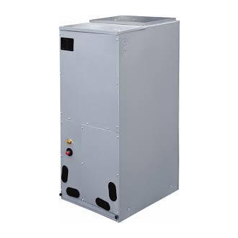
2 Product Introduction 2.1 Product Description The GREE air handler offer the perfect combination of superior product quality, operating efficiency, operating sound levels and value for money. The condensing unit uses the environmentally friendly refrigerant R410A, which is chlorine-free to help prevent damage to the ozone layer. -
Page 8: Names Of Main Parts
Air Handlers 2.3 Names of Main Parts 2.4 General Information Model Cooling capacity(ton) Optional electric heater (kW) GUD24AH2/A-D(U) 5/8/10 GUD36AH2/A-D(U) 5/8/10 GUD48AH2/A-D(U) 10/15/20 GUD60AH2/A-D(U) 10/15/20 Motor @ 230V ~, 60Hz Model GUD24AH2/A-D(U) GUD36AH2/A-D(U) GUD48AH2/A-D(U) GUD60AH2/A-D(U) Unit: mm Model Filter size GUD24AH2/A-D(U) 490×516×15... -
Page 9: Dip Switch Configuration
Model Level Heat (SA2) Cool (SA1) Level 1 Level 2 Level 3 Level 4-Default GUD24AH2/A-D(U) Level 5 Level 6 Level 7 Level 8 Level 1 Level 2 Level 3 Level 4-Default... -
Page 10: Fan Performance Data
Level 7 Level 8 NOTE: 0 means dip switch to ‘on’, 1 means dip switch to number. 2.6 Fan Performance Data Model GUD24AH2/A-D(U) Static pressure(Inches W.C.) Level 0.15 Speed 1(CFM) 1030 900 Speed 2(CFM) 1080 960 Speed 3(CFM) 1220 1120 1060... -
Page 11: Preparative For Installation
Air Handlers Model GUD36AH2/A-D(U) Static pressure(Inches W.C.) Level 0.15 Speed 1(CFM) 1150 1050 Speed 2(CFM) 1200 1100 1000 Speed 3(CFM) 1380 1260 1200 1100 Speed 4(CFM) 1550 1460 1390 1310 1160 1010 Speed 5(CFM) 1710 1650 1600 1560 1480 1400 1310 1210 1080 Speed 6(CFM) 1840 1800 1750 1710 1640 1590 1500 1420 1330 1220 1100 Speed 7(CFM) 1870 1830 1810 1800 1760 1690 1620 1520 1440 1350 1250 1150 Speed 8(CFM) 1900 1860 1840 1830 1790 1720 1660 1600 1540 1440 1320 1220... -
Page 12: Important Safety Instructions
Air Handlers 3.1.2 Before Installation Carefully read all instructions for the installation prior to installing product. Make sure each step or procedure is understood and any special considerations are taken into account before starting installation. Assemble all tools, hardware and supplies needed to complete the installation. - Page 13 Air Handlers The United States Environmental Protection Agency (“EPA”) has issued various regulations regarding the introduction and disposal of refrigerants introduced into this unit. Failure to follow these regulations may harm the environment and can lead to the imposition of substantial fines. These regulations may vary due to the passage of laws. A certified technician must perform the installation and service of this product.
-
Page 14: Installation
Air Handlers Special warning for installation of furnaces or air handling units in enclosed areas, such as garages, utility rooms or parking areas. Carbon monoxide producing devices (such as an automobile, space heater, gas water heater, etc.) should not be operated in enclosed areas such as unventilated garages, utility rooms or parking areas because of the danger of carbon monoxide (CO) poisoning resulting from the exhaust emissions. -
Page 15: Location
Air Handlers 4.2 Location This air handler is designed for indoor installation only. Do not install it outdoors. When installing the air handler, take consideration to minimize the length of refrigerant tubing as much as possible. Do not install the air handler in a location either above or below the condenser that violates the instructions provided with the condenser. -
Page 16: Piping Work
4.3 Piping Work 4.3.1 Specification of Connection Pipe External diameter (inch) Model Gas pipe Liquid pipe GUD24AH2/A-D(U) GUD36AH2/A-D(U) GUD48AH2/A-D(U) GUD60AH2/A-D(U) 4.3.2 Piping Preparation All cut ends are to be round, burr free, and cleaned. Failure to follow this practice increases the chances for refrigerant leakage. -
Page 17: Condensate Removal
Air Handlers 4.4 Condensate Removal It is not allowed to connect the condensate drain pipe into waste pipe or other pipelines which are likely to produce corrosive or peculiar smell to prevent the smell from entering indoors or corrupt the unit. It is not allowed to connect the condensate drain pipe into rain pipe to prevent rain water from pouring in and cause property loss or personal injury. -
Page 18: Ductwork
Air Handlers The drain pan has primary and secondary drain connection. Condensate removal is performed by attaching a 3/4” PVC pipe to the evaporator coil pan and terminated in accordance with local or state Plumbing/HVAC codes. The installation must include a “P” style trap that is located closely to the evaporator coil. - Page 19 Air Handlers Refer to the “Electric heater kits installation” section of this manual and the instructions provided with the heater kit for the correct installation procedure. The electrical characteristics of the air handler, the electric heater kit, and the supply power should be identical. This air handler does not have factory installed electric heater.
- Page 20 Air Handlers 4) Remove cover plate from air handler. 5) Slide the heater kit in to the slot and secure element plate with previously removed screws. 6) Insert power leads into the circuit breaker lugs or stripped red and black wires (for heater kit without circuit breaker) and tighten.
-
Page 21: Electrical Installation
Air Handlers 4.7 Electrical Installation 4.7.1 Requirement and Notice on Electrical Installation The electrical installation for the air conditioner should observe the following requirements: . The electrical installation must be conducted by professionals in compliance with local laws and regulations and the instructions in this manual. Never extend the power cords. - Page 22 Maximum Model Power supply circuit overcurrent ampacity (A) protection (A) GUD24AH2/A-D(U) GUD36AH2/A-D(U) 208/230V-1Ph-60Hz GUD48AH2/A-D(U) GUD60AH2/A-D(U) . Fuse is located on the main board. . Install a circuit breaker at every power terminal near the units (indoor unit and thermostat) with at least 3mm contact gap. The units must be able to be plugged or unplugged.
- Page 23 Air Handlers 1) Use wire cutters to cut off the wire end and then peel away about 10mm of the insulation layer. 2) Use a screwdriver to unscrew the terminal screw on the terminal board. 3) Use a round terminal fastener or clamp to fix the round terminal firmly on the peeled wire end.
- Page 24 Air Handlers . Before working, please check whether the indoor unit and thermostat are powered on. . Match the terminal numbers and wire colors with the colors indicated in the indoor unit. . Wrong wire connection may burn the electrical components. .
- Page 25 Air Handlers D means defrosting signal; R means 24V AC power supply; C means 24V common; G means indoor unit fan signal for the in door unit; W1 means heater control signal. NOTE: For cooling only unit, there is no need to connect the B and D terminals.
-
Page 26: Installation Check And Trial Run
Air Handlers 5 Installation Check and Trial Run 5.1 Checking Items after Installation Problems might happen due to Items to be checked Check improper installation Check if each parts of the unit have The unit might fall off, vibrate or emit been installed reliably. -
Page 27: Common Malfunction And Elimination
Air Handlers Check if the unit appearance and piping system has been damaged during transportation or handling. Check if the terminals are loose and the phases are correct. 5.2.2 Trial Run Trial run can be operated by professional personnel only after above items have been checked (items to be checked as per actual condition). - Page 28 Air Handlers NOTE: If reasons are still unclear after checking above items, please contact Gree service center and show phenomena and models. Following circumstances are not malfunction. “Malfunction” Reason When unit is started Overload protection switch immediately after it is just makes it run after 3 minutes turned off.
-
Page 29: Maintenance And Care
Air Handlers Different running indicator flashing light means different system failure. malfunction Running Indicator status Remark Indoor Jumper cap failure Light out 3S then flash once Indoor fan failure Light out 3S then flash Flash means light on twice 0.5S then light out 0.5S Indoor tube temperature Light out 3S then flash sensor failure... - Page 30 Air Handlers 8 After-Sales Service In case the air-conditioning unit you bought has any quality problem or you have any inquiry, please contact the local after-sales service agency designated by factory. Warranty should meet the following requirements: First run of the unit should be operated by professional personnel from factory appointed service center.
Need help?
Do you have a question about the GUD24AH2/A-D and is the answer not in the manual?
Questions and answers