
Related Manuals for Gree GUD36A/A-D(U)


Summary of Contents for Gree GUD36A/A-D(U)
- Page 1 Owner's Manual Original Instructions Air Conditioners Air Handlers Models: GUD36A/A-D(U)
- Page 2 To Users Thank you for selecting Gree’s product. Please read this instruction manual carefully before installing and using the product, so as to master and correctly use the product. In order to guide you to correctly install and use our product and...
- Page 3 The final right to interpret for this instruction manual belongs to Gree Electric Appliances Inc. of Zhuhai. Exception Clauses Manufacturer will bear no responsibilities when personal injury or property loss is caused by the following reasons: Damage the product due to improper use or misuse of the product.
-
Page 4: Table Of Contents
Contents 1 Safety Precautions ............1 2 Product Introduction ............2 2.1 Product Description ..............2 2.2 Optional Accessories..............2 2.3 Physical Dimension ..............3 2.4 Names of Main Parts ..............4 2.5 General Information ...............5 3 Preparative for Installation..........5 3.1 Pre-Installation Instruction ............5 3.2 Important Safety Instructions ..........6 4 Installation ................ - Page 5 7.4 Parts Replacement............... 24 8 After-Sales Service ............25 This marking indicates that this product should not be disposed with other household wastes throughout the EU. To prevent possible harm to the environment or human health from uncontrolled waste disposal, recycle it responsibly to promote the sustainable reuse of material resources.
-
Page 6: Safety Precautions
Air Handlers 1 Safety Precautions This product can’t be installed at corrosive, inflammable or explosive environment or the place with special requirements, such as kitchen. Otherwise, it will affect the normal operation or shorten the service life of the unit, or even cause fire hazard or serious injury. -
Page 7: Product Introduction
2 Product Introduction 2.1 Product Description The GREE air handler offer the perfect combination of superior product quality, operating efficiency, operating sound levels and value for money. The condensing unit uses the environmentally friendly refrigerant R410A, which is chlorine-free to help prevent damage to the ozone layer. -
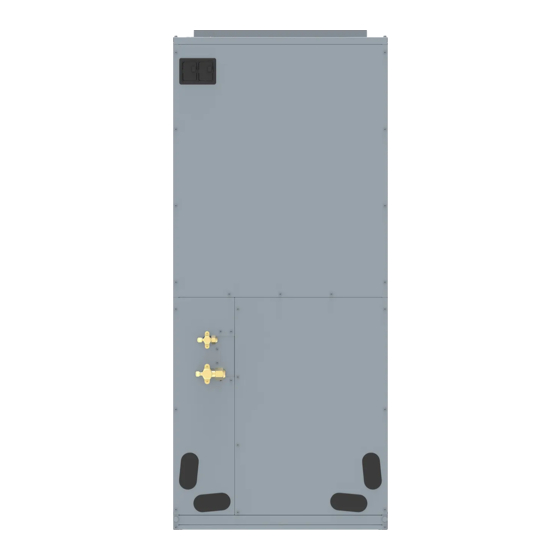
Page 8: Physical Dimension
Air Handlers 2.3 Physical Dimension Unit: inch(mm) Dimension Model GUD36A/A-D(U) 21-1/4(540) 21-1/4(540) 48-1/4(1224) 11-5/8(295) 20(508) -
Page 9: Names Of Main Parts
Air Handlers 2.4 Names of Main Parts... -
Page 10: General Information
Air Handlers 2.5 General Information Model Cooling capacity(ton) Optional electric heater (kW) GUD36A/A-D(U) Motor @ 230V ~, 60Hz Model GUD36A/A-D(U) Unit: mm Model Filter size GUD36A/A-D(U) 490×516×15 NOTES: ①. Based upon W/nominal tonnage, dry coil and filter should be installed. ②. -
Page 11: Important Safety Instructions
Air Handlers 3.1.4 Replacement Parts When reporting shortages or damages, or ordering repair parts, give the complete product model and serial numbers as stamped on the product. Replacement parts for this product are available through your contractor or local distributor. 3.2 Important Safety Instructions Recognize safety symbols, words, and labels The following symbols and labels are used throughout this manual to indicate... - Page 12 Air Handlers Due to high system pressure and electrical shock in potential, installation and service work can be dangerous. Only trained and qualified persons are permitted to install or service this equipment. Observe all warnings contained in this manual and labels/tags attached to the equipment.
-
Page 13: Installation
Air Handlers carbon monoxide (CO) poisoning resulting from the exhaust emissions. If a furnace or air handler is installed in an enclosed area such as a garage, utility room or parking area and a carbon monoxide producing device is operated therein, there must be adequate ventilation directly to outside. -
Page 14: Piping Work
Air Handlers that may lead to physical damage (i.e. a garage) it is advised to install a protective barrier to prevent such damage. This air handler is designed for a complete supply and return ductwork system. Do not operate this product without all ductwork attached. Based upon the actual conditions, if air handler is installed as Fig. - Page 15 Air Handlers 4.3.2 Piping Preparation 4.3.2.1 Solder Connection All cut ends are to be round, burr free, and cleaned. Failure to follow this practice increases the chances for refrigerant leakage.
-
Page 16: Condensate Removal
Air Handlers 4.3.2.2 Screw Connection Pipe diameter (inch) Tightening torque (N·m) Φ1/4 15-30 Φ3/8 35-40 Φ1/2 45-50 Φ5/8 60-65 Φ3/4 70-75 Φ7/8 80-85 4.4 Condensate Removal It is not allowed to connect the condensate drain pipe into waste pipe or other pipelines which are likely to produce corrosive or peculiar smell to prevent the smell from entering indoors or corrupt the unit. -
Page 17: Ductwork
Air Handlers and terminated in accordance with local or state Plumbing/HVAC codes. The installation must include a “P” style trap that is located closely to the evaporator coil. Do not over-tighten the drain connection in order to prevent possible damage to the evaporator drain pan. See the following figure for details of a typical condensate line “P”... -
Page 18: Electric Heater
Air Handlers introduce toxic, or objectionable fumes/odors into the ductwork. The return ductwork is to be introduced into the air handler bottom (up flow configuration). Return Air Filters: Each installation must include a return air filter. This filtering may be performed at the air handler or externally such as a return air filter grille. 4.6 Electric Heater The air handlers listed in this manual do not have factory installed electric heat. - Page 19 Air Handlers 3) Remove the upper access panel from air handler. 4) Remove cover plate from air handler. 5) Slide the heater kit in to the slot and secure element plate with previously removed screws. 6) Insert power leads into the circuit breaker lugs or stripped red and black wires (for heater kit without circuit breaker) and tighten.
-
Page 20: Electrical Installation
⑨. Please use the power cables that are delivered along with the air conditioner. Do not change the power cables arbitrarily. Do not change the length and terminals of the power cables. If you want to change the power cables, please contact Gree’s local service center. - Page 21 Air Handlers ⑩. Wiring terminals should be connected firmly to the terminal board. Loose connection is forbidden. ⑪. After the electrical installation is finished, please use wire clamps to secure the power cord, connection wire of indoor unit and temperature controller and the communication cords.
- Page 22 Air Handlers 4.7.2 Electrical Parameters Minimum Maximum Model Power supply circuit overcurrent ampacity (A) protection (A) GUD36A/A-D(U) 208/230V-1Ph-60Hz ①. Fuse is located on the main board. ②. Install a circuit breaker at every power terminal near the units (indoor unit and temperature controller) with at least 3mm contact gap.
- Page 23 Air Handlers 3) Use nippers to bend the solid wire into a ring that fits the terminal screw. 4) Form a proper ring and then put it on the terminal board. Use a screwdriver to tighten up the terminal screw. For strand wires (as shown below): 1) Use wire cutters to cut off the wire end and then peel away about 10mm of the insulation layer.
- Page 24 Air Handlers ①. Before working, please check whether the indoor unit and temperature controller are powered on. ②. Match the terminal numbers and wire colors with the colors indicated in the indoor unit. ③. Wrong wire connection may burn the electrical components. ④.
- Page 25 Air Handlers ①. High and low voltage wires should be led through different rubber rings of the electric box cover. ②. Do not bundle up the connection wire and communication wire of wired control or lay them side by side, otherwise errors will occur. ③.
-
Page 26: Installation Check And Trial Run
Air Handlers 5 Installation Check and Trial Run 5.1 Checking Items after Installation Problems might happen due to Items to be checked Check improper installation Check if each parts of the unit have The unit might fall off, vibrate or emit been installed reliably. -
Page 27: Common Malfunction And Elimination
Draw curtain or louver. Too much heat source in the Reduce heat source. room. Filter screen is blocked by Clean the filter. dirt. NOTE: If reasons are still unclear after checking above items, please contact Gree service center and show phenomena and models. - Page 28 Air Handlers Following circumstances are not malfunction. “Malfunction” Reason When unit is started Overload protection switch immediately after it is just makes it run after 3 minutes turned off. delay. Unit doesn’t run. Standby operating for about 1 When power is turned on. minute.
-
Page 29: Maintenance And Care
Air Handlers 7 Maintenance and Care Regular check, maintenance and care should be performed by professional personnel, which will prolong the unit life span. 7.1 Drain Pipe Regularly check if the drain pipe is clogged in order to drain condensate smoothly. - Page 30 Air Handlers 8 After-Sales Service In case the air-conditioning unit you bought has any quality problem or you have any inquiry, please contact the local after-sales service agency designated by factory. Warranty should meet the following requirements: First run of the unit should be operated by professional personnel from factory appointed service center.
Need help?
Do you have a question about the GUD36A/A-D(U) and is the answer not in the manual?
Questions and answers