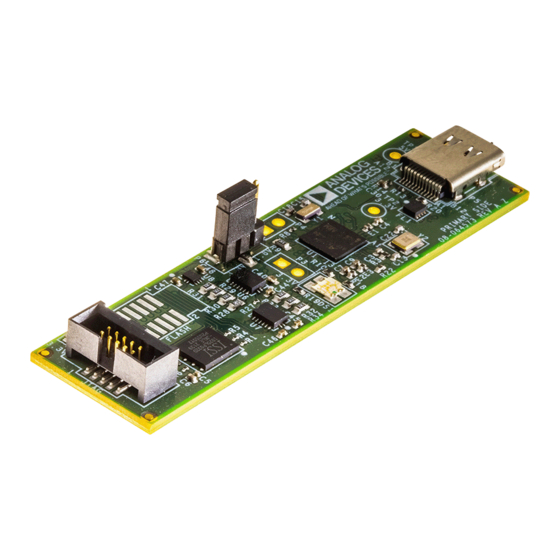
Summary of Contents for Analog Devices ICE-1500
- Page 1 ICE-1500 Emulator User Guide Revision 1.0, November 2024 Part Number 82-100617-01 Analog Devices, Inc. One Analog Way Wilmington, MA 01887...
-
Page 2: Copyright Information
Analog Devices, Inc. reserves the right to change this product without prior notice. Information furnished by Ana- log Devices is believed to be accurate and reliable. However, no responsibility is assumed by Analog Devices for its use; nor for any infringement of patents or other rights of third parties which may result from its use. No license is granted by implication or otherwise under the patent rights of Analog Devices, Inc. -
Page 3: Table Of Contents
PC Configuration ............................2–2 Emulator Installation ............................. 2–2 Installing the Emulator Software ........................ 2–2 ICE-1500: Configuring Operating Voltage of the JTAG/SWD Interface ............ 2–2 Verifying Driver Installation and Attaching to an Emulation Target ............2–2 Applying Power to the Emulator......................... 2–3 Configurator Software ........................... - Page 4 Support References ICE-1500 Emulator...
-
Page 5: Preface
Preface 1 Preface ® Thank you for purchasing the ICE-1500 emulator. The emulator is used in conjunction with the CrossCore bedded Studio or development environments to create, test, and debug advanced processor application software on ® ® ® Analog Devices SHARC... -
Page 6: What's New In This Manual
The updates to the manual include: • Modifications and corrections based on errata reports against the previous manual revision For the latest version of this manual, refer to the Analog Devices Web site. Technical Support You can reach Analog Devices processors and DSP technical support in the following ways: •... -
Page 7: Product Information
If you are a registered user, just log on. Your user name is your e-mail address. EngineerZone EngineerZone is a technical support forum from Analog Devices. It allows you direct access to ADI technical sup- port engineers. You can search FAQs and technical information to get quick answers to your embedded processing and DSP design questions. -
Page 8: Notation Conventions
A warning identifies conditions or inappropriate usage of the product that could lead to condi- tions that are potentially hazardous for devices users. In the online version of this book, the word ATTENTION: appears instead of this symbol. 1–4 ICE-1500 Emulator... -
Page 9: Getting Started
2 Getting Started This chapter provides the information needed to begin using Analog Devices emulators. NOTE: Analog Devices emulators are not intended to be used in a production environment. This chapter includes the following sections. • Contents of Emulator Package Provides a list of components shipped with the emulator. -
Page 10: Pc Configuration
Verifying Driver Installation and Attaching to an Emulation Target Before using the emulator, verify that the driver software is installed properly. 1. Open the Windows Device Manager and verify that the ICE-1500 emulator appears under CrossCore Tools, as shown in the Verifying Driver Installation figure. -
Page 11: Applying Power To The Emulator
Figure 2-1: Verifying Driver Installation 2. When connecting to a 10-pin header on a target board, connect to the 6" cable when using the ICE-1500. The 10-pin housing is keyed to ensure that the signals mate correctly with the 10-pin target emulation header. The target board should also have keyed housing. -
Page 12: Configurator Software
ICE test. JTAG/SWD Frequency The ICE-1500 emulator supports JTAG/SWD clock operation at 5 MHz. There is a relationship between the JTAG/SWD frequency and core clock frequency of the processor. The core clock should be at least twice the JTAG/SWD frequency in order for the JTAG/SWD interface to operate properly. On newer Analog Devices pro- cessors, the core clock is a variable set by software. -
Page 13: Troubleshooting And Warranty
Troubleshooting and Warranty To provide comprehensive troubleshooting advice and warranty information for all emulator and evaluation system products, Analog Devices maintains two engineer-to-engineer notes: • "Emulator and Evaluation Hardware Troubleshooting Guide for VisualDSP++ Users (EE-175)" • "Emulator and Evaluation Hardware Troubleshooting Guide for CCES Users (EE-356)"... -
Page 14: Hardware Description
• Cyan – signifies that the ICE is operating in SWD mode. The LED blinks during USB activity between the host PC and the emulator. • Yellow – signifies that there is an issue with the EMU signal on the target board and therefore this signal will be ignored by the emulator. ICE-1500 Emulator 3–1... -
Page 15: Connectors
Connectors There is one connector on the ICE-1500. This connects to the 6" ribbon cable that comes with the emulator pack- age. The ribbon cable connects to a 0.05" 10-pin connector on the target board and supports JTAG/ and SWD mode. -
Page 16: Quality Assurance
For technical support, visit the Support page at: http://www.analog.com/support. From there you can: • Access the EngineerZone DSP Support Forum where Analog Devices support team members and other design- ers exchange ideas and answer questions • Search our vast Knowledge Base containing application notes, data sheets, code examples, manuals, and more •... - Page 17 "Analog Devices JTAG/SWD Emu- lation Technical Reference (EE-68)", available from the Analog Devices website. • For information on the architecture and system interface of the Analog Devices processor, refer to the appropri- ate Analog Devices processor hardware reference manual.


Need help?
Do you have a question about the ICE-1500 and is the answer not in the manual?
Questions and answers