
Related Manuals for BEKA BA528E SP101


Summary of Contents for BEKA BA528E SP101
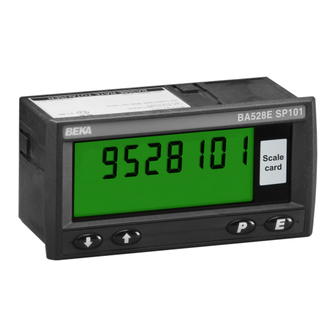
- Page 1 BA528E SP101 General Purpose 7 digit loop-powered panel mounting indicator Issue 1 Issue: 1 30th August 2024...
-
Page 2: Table Of Contents
6.3 Lineariser under and over-range 6.4 Lineariser default configuration The BA528E SP101 is CE marked to show compliance with the European EMC Directive 2014/30/EU. It is also UKCA marked to show compliance with UK Electromagnetic Compatibility Regulations UKSI 2016:1091 as amended... -
Page 3: Description
1. DESCRIPTION 2. OPERATION The BA528E SP101 is a general purpose, 7 digit Fig 1 shows a simplified block diagram of the panel mounting indicator based on the BEKA indicator. The 4/20mA input current flows through 5 digit BA528E. resistor R1 and forward biased diode D1. -
Page 4: Controls
P + E Access to configuration menu via optional security code. 3.2 Remote indication The BA528E SP101 may be driven from a 4/20mA signal to provide a remote indication. Fig 3 shows Note: Φ If the indicator has been calibrated... -
Page 5: Installation
Fig 3 Indicator providing a remote display 4. INSTALLATION 4.1 Location The BA528E SP101 has a robust glass reinforced Noryl enclosure with a toughened glass window. The front of the indicator has IP66 protection and a gasket seals the joint between the instrument enclosure and the panel. -
Page 6: Installation Procedure
Four panel mounting clamps are required to that the tapered section is held by the rear panel. achieve IP66 seal between BA528E SP101 indicator and the instrument panel. Align self-adhesive Connect the panel wiring to the rear terminal printed scale card onto the block(s) as shown in Fig 4. -
Page 7: Emc
4.4 EMC The BA528E SP101 indicator complies with the requirements of the European EMC Directive 2014/30/EU and UK Electromagnetic Compatibility Regulations UKSI 2016:1091 (as amended). For specified immunity all wiring should be in screened twisted pairs, with the screens earthed at one... -
Page 8: Configuration And Calibration
5. CONFIGURATION AND CALIBRATION 5.1 Summary of configuration functions The BA528E SP101 indicator is configured and This section summarises each of the main calibrated via the four front panel push buttons. configuration functions and includes a cross All the configuration functions are contained in an reference to a more detailed description. - Page 10 5.2 Indicator function: ‘FunC’ Display Summary of functions This configuration function defines the relationship between the indicator’s 4/20mA input current and 'tArE' Tare function the indicator’s display. Three alternatives are When enabled the tare function sets available: indicator display zero, ‘Std’...
-
Page 11: Calibration Using An External
Notes: a. The resolution and accuracy of the external calibrated current source should be appropriate for the number of digits the BA528E SP101 indicator is being calibrated to display. b. The indicator input current must be adjusted to the required value before the zero and span functions are entered by pressing the P button. -
Page 12: Calibration Using Internal Reference
‘CodE’ prompt. The revised security code will be activated when the indicator is returned to the display mode. Please contact BEKA associates 5.7 Function of the P push button: ‘C - - P’ sales department if the security code is lost. -
Page 13: Reset To Factory Defaults
Jump-out should then be increased until the 5.11 Filtering and stability: 'FiLtEr' selected step size is greater than the noise on the Because the BA528E SP101 can have 7 active display, at which setting the display should become digits to display the 4/20mA input, the least stable. -
Page 14: Lineariser Calibration Using An External Current Source
6. LINEARISER 6.1 Lineariser calibration using an external A sixteen segment, seventeen break-point (0 to 16) current source. lineariser may be selected in the ‘FunC’ section of This method allows direct calibration of the the configuration menu. The position of each lineariser with an external current source and is the break-point is fully adjustable so that the slope of preferred method when traceability is required. -
Page 16: Lineariser Calibration Using Internal Reference
The delete break-point sub-function 'dEL' operates in a display of '1:2'. If more new break-points are in exactly the same way as the 'Add' sub-function required, using the ▲ button select the new described above. Once within the ‘dEL’ sub- highest break-point '2:2' and add the second function each time the P button is pressed a break- additional break-point by operating the P push... -
Page 17: Example, Adding Break-Points To A New Indicator
To add a break-point using the ▲ or ▼ button and the P button to move between digits, to enter select '5Et' from the configuration menu and press the required indicator display at the first break- P which will result in the 'Add' sub-function prompt point. -
Page 18: Fault Finding During Commissioning
Indicators which fail within the guarantee period lost. should be returned to BEKA associates or your local BEKA agent. It is helpful if a brief description Note: of the fault symptoms is provided. Depending upon the indicator calibration, the... -
Page 19: Scale Card
8. ACCESSORIES 8.1 Scale card All models have a window on the right hand side of the display through which to view a scale card showing the units of measurement such as mBar, RPM. New indicators are fitted with a scale card showing the units of measurement specified when the indicator was ordered, if the units are not specified a blank scale card will be fitted. -
Page 21: Configuration And Adjustment
Summary of alarm configuration functions Display Summary of functions 'EnbL’ Alarm enable Enables or disables the alarm without changing the alarm parameters. See section 8.3.3 '5P1' Alarm setpoint 1 Adjusts the alarm setpoint. The alarm is activated when the indicator display equals the setpoint. - Page 22 8.3.3 Alarm enable: ‘EnbL’ To check or change the alarm output status, select This function allows each alarm to be enabled or 'no.nC' from the alarm configuration menu and disabled without altering any of the alarm press P to reveal the setting. The function may be parameters.
-
Page 23: Access Setpoint In Display
8.3.9 Alarm silence time: 5iL indicator is in the display mode is provided by a This function is primarily intended for use in small separate security code. installations where the alarm output directly operates an alarm annunciator such as a sounder This direct setpoint access menu is enabled and or beacon. - Page 24 Fig 14 Setpoint adjustment from the display mode To adjust an alarm setpoint select '5P1' or '5P2' and press P which will reveal the current setting. Each digit of the setpoint may be adjusted using the ▲ and ▼ push buttons, and the P button to move control to the next digit.
-
Page 25: Display Backlight
8.4 Display backlight 8.4.2 Separately powering the backlight The BA528E SP101 loop powered indicator can be The optional backlight may also be powered from a supplied with a factory fitted backlight that may be separate safe area power supply via an intrinsically loop or separately powered.
Need help?
Do you have a question about the BA528E SP101 and is the answer not in the manual?
Questions and answers