
Related Manuals for BEKA BA507E


Summary of Contents for BEKA BA507E
- Page 1 Installation & Maintenance Instructions BA507E, BA508E, BA527E, BA528E Supplied by .com Call us on +44 (0)118 916 9420 | Email info@247able.com...
- Page 2 Installation & Maintenance Instructions BA507E, BA527E, BA508E & BA528E General purpose loop-powered panel mounting indicators Reading Office Aberdeen Office Cutbush Park, Danehill, Lower Earley, Unit 6 Airside Business Park, Kirkhill Industrial Estate, Internet: www.able.co.uk Reading, Berkshire. RG6 4UT. UK. Dyce, Aberdeen. AB21 0GT. UK.
- Page 3 BA507E, BA527E, BA508E & BA528E General Purpose loop-powered panel mounting indicators issue 3 Issue: 3 1st December 2012...
-
Page 4: Table Of Contents
6.1 Lineariser calibration using an external current source. 6.2 Lineariser calibration using internal reference. 6.3 Lineariser error message 6.4 Lineariser under and over-range 6.5 Lineariser default configuration The BA507E, BA527E, BA508E & BA528E are CE marked to show compliance with the European EMC Directive 2004/108/EC... -
Page 5: Description
4/20mA current, e.g. temperature, flow, pressure or level. Fig 1 Indicator block diagram The BA507E, BA527E, BA508E and the BA528E are not certified for use in explosive atmospheres. For hazardous area applications the BA307E, BA327E, BA308E or the BA328E should be used. -
Page 6: Controls
P + E Access to configuration menu via a typical application in which the 4/20mA output optional security code. from a gas analyser is connected to a BA507E loop powered indicator to provide a remote Note: * BA527E and BA528E only indication of the analyser’s output. -
Page 7: Installation
The indicators may be installed in any panel providing that the operating temperature between –40ºC and +70ºC. Fig 4A BA507E and BA527E dimensions Figs 4A and 4B show the overall dimensions of the 96 x 48mm and the 144 x 72mm instruments together with the recommended panel cut-out dimensions. -
Page 8: Installation Procedure
4.2 Installation Procedure a. Cut the specified aperture in the panel. To achieve an IP66 seal between the instrument enclosure and the instrument panel the aperture must have the tighter tolerances specified in Fig 4A and 4B. b. Slide the gasket over the body of the indicator before inserting the instrument into the panel aperture. -
Page 9: Scale Card
A pack of self-adhesive scale cards printed with common units of measurement is available as an accessory from BEKA associates. Custom printed scale cards can also be supplied. To change a scale card, unclip the protruding end of the flexible strip by gently pushing it upwards and pulling it out of the enclosure. -
Page 10: Configuration And Calibration
If calibration is indicator to be adjusted without the not requested, indicators will be configured as need for an accurate input current or follows: disconnection from the 4/20mA loop. BA507E BA527E See section 5.6 BA508E BA528E Access code ‘CodE’ 0000 0000... -
Page 12: Resolution
Display Summary of function 5.2 Indicator function: ‘FunC’ This configuration function defines the relationship 'C - - P' Function of P push-button between the indicator’s 4/20mA input current and The indicator may be configured to the indicator’s display. Three alternatives are display the input current in milliamps, or available: the input current as a percentage of the... -
Page 13: Calibration Using An External
5.4 Position of the decimal point: ‘dP’ 5.6 Calibration using internal reference: ‘SEt’ A dummy decimal point can be positioned between Using the ‘SEt’ function the indicator can be any of the digits or it may be absent. To position calibrated without the need for an accurate the decimal point select 'dP' from the menu and external current source and without the need to... -
Page 14: Function Of The P Push-Button
E twice will return the display activated when the indicator is returned to the to the ‘bAr’ prompt in the configuration menu. display mode. Please contact BEKA associates sales department if the security code is lost. Note: ‘bArLo’ must be set lower than ‘bArHi’, incorrect setting is indicated by the bargraph scale flashing with a single bargraph segment activated. -
Page 15: Lineariser
level sensor in an irregular tank may be displayed 6. LINEARISER A sixteen segment, seventeen breakpoint (0 to 16) in linear volumetric units by filling the tank with lineariser may be selected in the ‘FunC’ section of known incremental volumes and calibrating the the configuration menu. -
Page 17: Lineariser Calibration Using Internal Reference
When the required number of break-points have 'dEL' Remove a break-point been entered, return to the linearisation sub-menu Removes the displayed break-point and by pressing E. The indicator will display the 'Add' joins the preceding break-point to the or 'dEL' prompt depending upon the last function following break-point with a straight used. -
Page 18: Lineariser Error Message
P in section 5.11, the defaults conditions are: and enter the indicator input current at which this break-point is required. Repeat this procedure until BA507E BA527E BA508E BA528E the indicator input current at all the break-points First break-point 4mA 0.00... -
Page 19: Fault Finding During Commissioning
Indicators which fail within the guarantee period loop. should be returned to BEKA associates or our local All decimal points Underrange if Recalibrate the agent. It is helpful if a brief description of the fault flashing. -
Page 20: Scale Card
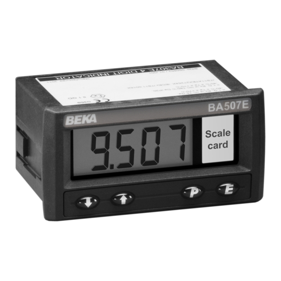
displayed value, but this will correspond to a 8. ACCESSORIES different input current. 8.1 Scale card All models have a window on the right hand side of the display through which to view a scale card showing the units of measurement such as mBar, RPM. -
Page 22: Configuration And Adjustment
Fig 12. The additional functions appear Adjusts the alarm hysteresis. between the ‘SEt’ and the ‘C- - P’ functions for the See section 8.3.7 BA507E and BA508E indicators, and between ‘bAr’ and ‘C- -P’ for the BA527E and BA528E 'dELA' Alarm delay time indicators. - Page 23 To check or change the alarm output status, select 8.3.3 Alarm enable: ‘EnbL’ This function allows each alarm to be enabled or 'no.nC' from the alarm configuration menu and disabled without altering any of the alarm press P to reveal the setting. The function may be parameters.
-
Page 24: Access Setpoint In Display
indicator is in the display mode is provided by a 8.3.9 Alarm silence time: SiL This function is primarily intended for use in small separate security code. installations where the alarm output directly operates an alarm annunciator such as a sounder This direct setpoint access menu is enabled and or beacon. -
Page 25: Displaying Setpoints On
8.3.13 Displaying setpoints on bargraph One of the selectable bargraph formats ‘AlrSP’ allows a low or a high setpoint plus the displayed value to be represented, or a low and a high setpoint plus the displayed value to be represented by the bargraph as shown in Fig 15. -
Page 26: Display Backlight
8.4 Display backlight 8.4.2 Separately powering the backlight The BA507E, BA527E, BA508E and BA528E loop The optional backlight may also be powered from a powered indicators can be supplied with a factory separate safe area power supply via an intrinsically fitted backlight that may be loop or separately safe interface as shown in Fig 18.
Need help?
Do you have a question about the BA507E and is the answer not in the manual?
Questions and answers