
Related Manuals for BEKA BA527C


Summary of Contents for BEKA BA527C
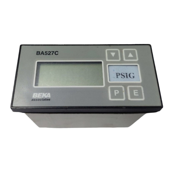
- Page 1 BA527C & BA528C loop-powered 4½ digit panel mounting indicators Issue 3 Issue: 3 5th March 2009...
-
Page 2: Table Of Contents
Using an external current source Using the internal calibrator Maintenance Fault finding during commissioning Fault finding after commissioning Servicing Routine maintenance Guarantee Customer comments The BA527C and BA528C indicators are CE marked to show compliance with the European EMC Directive 2004/108/EC... -
Page 3: Description
1. Description The BA527C and BA528C are 4½ digit loop Each time a 4/20mA current is applied to the powered digital indicators which display the current instrument, initialisation is performed. After a short flowing in a 4/20mA loop in engineering units. Both delay the following display sequence occurs: instruments introduce less than a 1.1V drop which... -
Page 4: Application
Noryl bezels. The fronts of both instruments have IP65 protection, and a gasket Fig 2 BA527C or BA528C in a transmitter loop seals the joint between the instrument enclosure and the panel. The indicators may be installed in... -
Page 5: Installation Procedure
Fig 4A BA527C dimensions Fig 4B BA528C dimensions 4.2 Installation Procedure a. Insert the indicator into the instrument panel Connect the panel wiring to the rear terminal from the front of the panel. block(s) as shown in Figs 4A and 4B. To... -
Page 6: Emc
4.3 EMC decimal points for a few seconds while the new The BA527C and BA528C comply with the information is stored in permanent memory. requirements of the European EMC Directive 2004/108/EC. For specified immunity all wiring All new BA527C and BA528C indicators are should be in screened twisted pairs. -
Page 7: Summary Of Programmable Functions
5.1 Summary of programmable functions Display Description of function This section summarises each of the main programmable functions includes cross 'Cond' Indicator conditioning references to more detailed information. Fig 6 This function provides access to a illustrates the location of each function within the sub-menu enabling internal... -
Page 9: Root Extractor
5.2 Root extractor: root This function is primarily intended for use with The indicator will display 'Ent' for a few seconds differential flowmeters which have a square law while the information is being stored in memory, 4/20mA output. To activate the square root and will then return to the 'ZErO' prompt. - Page 10 5.7 Conditioning sub-menu: Cond This sub-menu allows the mains (line) frequency at The accuracy of the internal references, and hence which the indicator has maximum ac rejection to be the display accuracy, will depend upon the selected and the two internal references to be accuracy of the external current source.
- Page 11 The following examples illustrate the two ways in Unscrew the four corner screws securing the rear which a BA527C or BA528C indicator may be panel and lift off the panel which will reveal the link calibrated.
-
Page 12: Position Of Decimal Point
Step 4 Select frequency of max rejection 6.2 Using the internal calibrator Scroll though the main menu until As in 6.1 the BA527C is required to display: 'Cond' is displayed. Enter the sub- menu by pressing P twice and select -50.0 with a 4mA input the 'FrE' function. - Page 13 See Fig 7. 7.2 Fault finding after commissioning ENSURE PLANT SAFETY BEFORE STARTING MAINTENANCE If a BA527C or BA528C fails after it has been functioning correctly, the following procedure should be followed:...
- Page 14 8.1 Scale card between The BA527C and the BA528C have a window on terminals the right hand side of the display to hold a card 1 and 3. showing the units of measurement e.g. °C, mBar, RPM.
- Page 15 See section 8.3.5 8.3.2 Programming and adjustment 'no.nc' Normally open or normally closed When an alarm card is added to a BA527C or output BA528C indicator the main programme menu is Determines whether the single pole extended as shown in Fig 12. The additional...
- Page 16 8.3.3 Alarm enable: EnbL 8.3.7 Hysteresis: HStr This function allows the alarm to be enabled or During programming hysteresis is shown in the disabled without altering any of the alarm units the indicator has been calibrated to display. parameters. To check or change the function To adjust the hysteresis select 'HStr' from the select 'EnbL' from the alarm menu and press P alarm menu and press P which will reveal the...
- Page 17 8.3.10 Access Setpoint: AcSP This function controls a separate menu that If the correct code is entered pressing E will cause provides direct access to the alarm setpoints when alarm setpoint prompt 'SP1' to be displayed. the indicator is in the display mode. See section Pressing the Up or Down button will toggle the 8.3.11 for a full description.
- Page 18 Fig 12 Alarm programme menu...
-
Page 19: Calibration Using An External Current
8.4 Lineariser Both indicators can be supplied with a sixteen The number of break-points required should first point lineariser that adjusted be entered using the Add and dEL functions. In compensate for almost any non linear variable. For both these functions the indicator initially displays example, a level signal from a horizontal cylindrical the current break-point and the total number of tank may be linearised by the indicator to display... -
Page 20: Calibration Using Internal References
Repeat this procedure for each break-point, and Select 'SEt' from the main menu and press P once then return to the main menu by pressing E twice. to enter the 'Add' function, and again to reveal the current and total number of break-points. Each 8.4.2 Calibration using internal references subsequent operation of the P push-button will This function enables the break-points to be... - Page 22 8.5 Tare function 8.6 Display backlight The tare function is a factory fitted software The BA527C and BA528C can be supplied with accessory, primarily intended for use with weighing LED backlighting to improve display contrast when systems. the indicator is installed in poorly illuminated areas.
Need help?
Do you have a question about the BA527C and is the answer not in the manual?
Questions and answers