
Related Manuals for BEKA BA504E


Summary of Contents for BEKA BA504E
- Page 1 BA504E & BA524E General Purpose loop-powered field mounting indicators Issue 2 Issue: 2 December 2011...
-
Page 2: Table Of Contents
6.2 Lineariser calibration using internal 8.5 Pipe mounting kits reference. 6.3 Lineariser error message 6.4 Under and over-range 6.5 Lineariser default configuration The BA504E & BA524E are CE marked to show compliance with the European EMC Directive 2004/108/EC... -
Page 3: Description
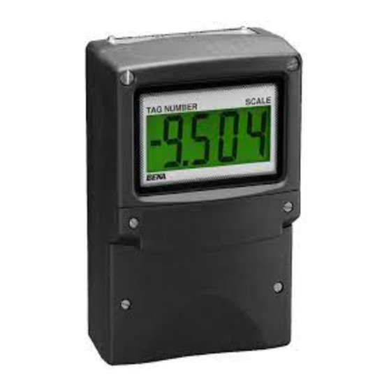
4/20mA current, e.g. temperature, flow, pressure or level. The BA504E and BA524E are not certified for use in explosive atmospheres. For hazardous area application the BA304E, BA304NE, BA324E or the BA324NE should be used. -
Page 4: Controls
2.1 Controls 3. APPLICATIONS The indicators are controlled and calibrated via four push-button switches located behind the 3.1 Transmitter loops instrument control cover, or as an option on the Both models may be connected in series with any control cover. In the display mode i.e. -
Page 5: Installation
Connect the field wiring to the terminals as shown in Fig 5. 4. INSTALLATION e. Replace the instrument terminal cover and evenly tighten the two 'A' screws. 4.1 Location The BA504E and BA524E indicators are housed in robust IP66 glass reinforced polyester (GRP) enclosures incorporating armoured glass... -
Page 6: Emc
Fig 5 Dimensions and terminal connections 4.3 EMC Both instruments compy with the requirements of the European EMC Directive 2004/108/EC. specified immunity all wiring should be in screened twisted pairs, with the screens connected at one point to the plants potential equalising conductor. -
Page 7: Configuration And Calibration
4/20mA loop. See section 5.6 Default Configuration BA504E BA524E 'bAr' Bargraph format and calibration Access code ‘CodE’ 0000 0000 Only the BA524E has a bargraph Function ‘FunC’... -
Page 9: Resolution
5.2 Indicator function: ‘FunC’ Display Summary of function This configuration function defines the relationship 'C - - P' Function of P push-button between the indicator’s 4/20mA input current and The indicator may be configured to the indicator’s display. Three alternatives are display the input current in milliamps, or available: the input current as a percentage of the... -
Page 10: Calibration Using An External
5.6 Calibration using internal reference: ‘SEt’ 5.4 Position of the decimal point: ‘dP’ A dummy decimal point can be positioned between Using the ‘SEt’ function the indicator can be any of the digits or it may be absent. To position calibrated without the need to know the value of the decimal point select 'dP' from the menu and the 4/20mA input current, or to disconnect the... - Page 11 Please Note: ‘bArLo’ must be set lower than ‘bArHi’, contact BEKA associates sales department if the incorrect setting is indicated by the bargraph scale security code is lost. flashing with a single bargraph segment activated.
-
Page 12: Current Source
6. LINEARISER level sensor in an irregular tank may be displayed A sixteen segment, seventeen breakpoint (0 to 16) in linear volumetric units by filling the tank with lineariser may be selected in the ‘FunC’ section of known incremental volumes and calibrating the the configuration menu. -
Page 14: Lineariser Calibration Using Internal Reference
When the required number of linearising break- 'dEL' Remove a break-point points have been entered, return Removes the displayed break-point linearisation sub-menu by pressing E. and joins the preceding segment to the indicator will display the 'Add' or 'dEL' prompt following segment with a straight line. -
Page 15: Lineariser Error Message
▲ and ▼ in section 6.11, the defaults conditions are: buttons. When the required break-point has been selected press P and enter the indicator input BA504E BA524E First break-point 4mA 0.00 current at this break-point. Repeat this procedure Second break-point 20mA 100.0... -
Page 16: Fault Finding During Commissioning
Indicators which fail within the guarantee period loop. should be returned to BEKA associates or our local All decimal points Underrange if Recalibrate the agent. It is helpful if a brief description of the fault flashing. -
Page 17: External Keypad
The open circuit condition should Both the BA504E and the BA524E indicators are therefore be chosen as the alarm condition when fitted with a blank escutcheon around the liquid designing an alarm system. -
Page 18: Solid State Output
8.3.1 Solid state output Each alarm has a galvanically isolated single pole solid state switch output which as shown in Fig 10. The output is polarised and current will only flow in one direction. less than 5Ω + 0.7V Roff greater than 1MΩ... -
Page 20: Configuration And Adjustment
Fig 12. The additional functions appear between the ‘SEt’ and the ‘C- - P’ functions for the 'EnbL’ Alarm enable BA504E and between ‘bAr’ and ‘C- -P’ for the Enables or disables the alarm without BA524E indicator. For simplicity, Fig 12 only changing the alarm parameters. - Page 21 To check or change the alarm output status, select 8.3.3 Alarm enable: ‘EnbL’ This function allows each alarm to be enabled or 'no.nC' from the alarm configuration menu and disabled without altering any of the alarm press P to reveal the setting. The function may be parameters.
-
Page 22: Access Setpoint In Display
indicator is in the display mode is provided by a 8.3.9 Alarm silence time: SiL This function is primarily intended for use in small separate security code. installations where the alarm output directly operates an alarm annunciator such as a sounder This direct setpoint access menu is enabled and or beacon. -
Page 23: Displaying Setpoints On Ba524E Bargraph
8.3.13 Displaying setpoints on BA524E bargraph One of the selectable bargraph formats ‘AlrSP’ allows a low or a high setpoint plus the displayed value to be represented, or a low and a high setpoint plus the displayed value to be represented by the bargraph as shown in Fig 14. -
Page 24: Display Backlight
8.4 Display backlight 8.4.2 Separately powering the backlight The BA504E and BA524E loop powered indicators The optional backlight may also be powered from a can be supplied with a factory fitted backlight that separate power supply as shown in Fig 16. -
Page 25: Pipe Mounting Kits
8.5 Pipe mounting kits Two pipe mounting kits are available for securing the BA504E and BA524E to a horizontal or vertical pipe. BA392D Stainless steel bracket secured by two worm drive hose clips. Will clamp to any vertical or horizontal pipe with an outside diameter between 60 and 80mm.
Need help?
Do you have a question about the BA504E and is the answer not in the manual?
Questions and answers