
Related Manuals for BEKA BA526C


Summary of Contents for BEKA BA526C
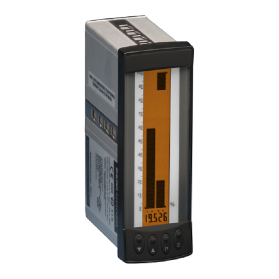
- Page 1 BA526C loop-powered analogue bargraph and digital indicator issue 9 Alarm Analogue setpoints display Label information Digital display Alarm Push annunciators buttons Issue: 1st June 2017...
-
Page 2: Table Of Contents
CONTENTS Description Maintenance 7.1 Fault finding during commissioning Operation 7.2 Fault finding after commissioning 2.1 Controls 7.3 Servicing 7.4 Routine maintenance 7.5 Guarantee Applications 7.6 Customer comments 3.1 Transmitter loops 3.2 Remote indication Accessories Installation 8.1 Units of measurement and 4.1 Location instrument identification. -
Page 3: Description
BA526B. The main application of the BA526C is to display a measured variable or control signal in a process area. The zero and span of the digital display are... -
Page 4: Controls
Controls APPLICATIONS The BA526C is controlled and calibrated via four front panel push-button switches. In the display Transmitter loops mode i.e. when the instrument is displaying a A BA526C indicator may be connected in series 4/20mA input current, these switches have the... -
Page 5: Remote Indication
Remote indication INSTALLATION A BA526C may be driven from any 4/20mA signal to provide a remote indication. Fig 3 shows a Location typical application in which the output from a gas The BA526C indicator is housed in a robust analyser drives a BA526C. -
Page 6: Installation Procedure
Installation Procedure illustrates instrument installation The BA526C complies with the requirements of the procedure. European EMC Directive 2014/30/EU. specified immunity all wiring should be in screened a. Insert the BA526C into the instrument panel twisted pairs, with the screens earthed at only one from the front of the panel. -
Page 7: Summary Of Programmable Functions
100 segment bargraphs. information is stored in permanent memory. See section 5.7 All new BA526C indicators are supplied calibrated 'CAL' Calibration displays using as requested at the time of ordering. - Page 8 50 or 60Hz may be selected. units. For inputs below 4.04mA the BA526C This function must be set before the displays zero. To activate the square root extractor instrument is calibrated as it effects the indicator display.
-
Page 9: Calibration Using An External
'bAr' from the main menu and press P which will span. The indicator will display 'Ent' for a few reveal if the BA526C is programmed to display a seconds while the information is being stored in column 'Col' or a single segment 'SEg'. -
Page 10: Calibration Using Internal References
Calibration using internal references: 5.10.1 AC rejection: FrE This function enables the zero and span of the CAUTION digital indicator to be adjusted without the need for mains filter frequency accurate external current source, changed, the indicator display and disconnection from the 4/20mA loop. internal references (if used) must be The accuracy of this method depends upon the recalibrated. -
Page 12: 5.11 Function Of The P Push-Button
0.4µA. 5.12 Null display function: null This function enables the BA526C analogue bargraph to operate as a deviation indicator 5.11 Function of the P push-button: displaying the difference between the input current and a specified reference. - Page 13 To define the input about which deviation is to be 5.13 Security code: COdE displayed the BA526C must be returned to the The calibration and conditioning of the instrument display mode. With the instrument displaying the may be protected by a four digit security code...
-
Page 14: 5.14 Over And Under-Range
CALIBRATION EXAMPLES The following examples illustrate the two ways in which a BA526C indicator may be calibrated. Using an external current source The BA526C indicator is required to display: with a 4mA input 1500.0 with a 20mA input from a linear level transducer. Maximum display... -
Page 15: Using The Internal References
Select 'C--P' from the main menu and Using the internal references press P to reveal the function of the P As in 6.1 the BA526C is required to display: button in the display mode. Select percentage 'PC' and return to the main... -
Page 16: Maintenance
'Cond' is displayed. Enter the sub- Fault finding during commissioning menu by pressing P twice and select If a BA526C fails to function during commissioning the 'FrE' function. Using the Up or the following procedure should be followed: Down buttons select '50',... -
Page 17: Fault Finding After Commissioning
The interval between inspections depends upon environmental conditions. We recommend that initially instrument calibration should be checked If specified at the time of ordering, the BA526C can annually. be supplied with tag or applicational information printed onto the instrument certification label which is located on the side of the enclosure. -
Page 18: Alarms
If only one alarm is enabled the setpoint will be indicated by a column extending from the setpoint All BA526C indicators include dual alarm functions, to the top of the display for a high alarm, and from which may be used to show acceptable operating... -
Page 19: Solid State Output
8.2.2 Programming and adjustment When an alarm card is added to a BA526C the main programme menu is extended as shown in Fig 14. The additional functions appear between 'Cond' and 'C--P' in the main menu. -
Page 20: Alarm Enable
Main menu Alarms Main menu Cond ALr1 ALr2 AcSP C - - P EnbL AcCd As ALr1 0000 Access Enable Security Code For Direct Access to to toggle Setpoints between On and OFF Enter code by pressing to move to next digit Code 0000 allows direct... -
Page 21: Setpoint Adjustment
'dELA' Alarm delay time 8.2.5 Alarm function: HI.LO Adjusts the delay between the display Each alarm can be conditioned as a high or low equalling the setpoint and the alarm alarm. To check or change the alarm function output being activated. select 'HI.LO' from the alarm menu and press P to See section 8.2.8 reveal the current setting. -
Page 22: Alarm Delay
8.2.8 Alarm delay: dELA To check or change the display alarm identification status select 'FLASH' from the alarm menu and This function enables activation of the alarm output press P to reveal the current setting. The function to be delayed for a fixed time following the alarm condition occurring. -
Page 23: Lineariser
setpoints are not protected by a security code the the next digit. When the required setpoint has alarm setpoint prompt 'SP1' will be displayed. If been entered, pressing E will return the display to the setpoints are protected by a security code, the 'SP1' or 'SP2' prompt from which the other 'COde' will be displayed first. -
Page 25: Calibration Using An
8.3.1 Calibration using an external current When the required number of break-points has been entered, return to the sub-menu by pressing source: CAL The indicator will display 'Add' or 'dEL' This method allows direct calibration with a current depending upon the last function used. Each source, and is preferred... - Page 26 Display Description of function To enter the required display at any break-point select 'dISP' from the sub-menu and press P which will select the first break-point '0 n', where 'n' is the 'Add' Add a break-point total number of break-points selected. Adds a new break-point before the selected break-point can be changed using the Up displayed break-point.
-
Page 27: Display Backlight
Display backlight BA526C supplied with backlighting to improve display contrast when the indicator is installed in poorly illuminated areas. The backlight is electrically isolated from the measuring circuit and may be powered from any 18 to 30V dc supply. The backlight brilliance may...
Need help?
Do you have a question about the BA526C and is the answer not in the manual?
Questions and answers