Table of Contents
Advertisement
Quick Links
Advertisement
Table of Contents

Related Manuals for BEKA BA554D


Summary of Contents for BEKA BA554D
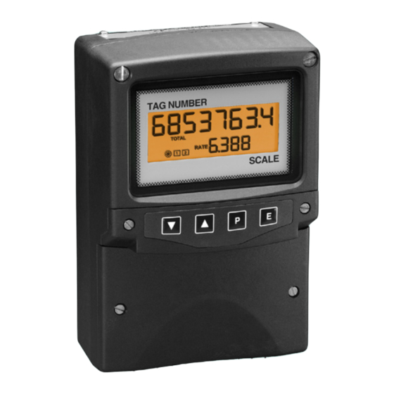
- Page 1 BA554D 4/20mA loop-powered field mounting rate totaliser Issue: September 2000...
-
Page 2: Table Of Contents
8.5 Pipe mounting kits 5.13 Total scale factor 8.6 Stem mounting kit 5.14 Percentage clip-off 5.15 Local reset of total display Index 5.16 Security code 5.17 Over and under-range The BA554D is CE marked to show compliance with the European EMC Directive 89/336/EEC... -
Page 3: Description
2.1 Controls 2. OPERATION The BA554D is controlled and calibrated via four Fig 1 shows a simplified block diagram of a push-button switches which are located behind BA554D. The 4/20mA input current flows... -
Page 4: Displays
While this button is pushed the rate 3.1 Flow transmitter loops display will show the input current in A BA554D rate totaliser may be connected in mA, or as a percentage of the series with any 4/20mA flow loop and calibrated... -
Page 5: Installation
4. INSTALLATION 4.1 Location The BA554D rate totaliser is housed in a robust IP66 glass reinforced polyester (GRP) enclosure incorporating an armoured glass window and stainless steel fittings. It is suitable for exterior mounting in most industrial environments, including off-shore and waste water treatment. -
Page 6: Emc
The BA554D complies with the requirements of the European EMC Directive 89/336/EEC. For specified immunity all wiring should be in screened twisted pairs, with the screens earthed at one point. Additional immunity may be obtained by connecting the BA554D earth terminal to a cable screen. -
Page 7: Programming And Calibration
BA554D uses floating different units. point arithmetic. Moving the position of the decimal point in the rate display will therefore For example, if a BA554D is displaying rate in affect totalisation. litres per minute, setting 'SCALE-t' to 4.5461 produces a total display gallons. -
Page 10: Summary Of Programmable Functions
If calibration information is not supplied, the BA554D will be set to display a rate of 0.00 with Enables the zero and span of the 4mA input and 100.00 with 20mA input. - Page 11 Display Description of function Display Description of function 'Cond' Indicator conditioning 'SCALE-t' Total Scale Factor This is a protected sub-menu Defines the arithmetic relationship which contains calibration between rate total routine internal displays. adjusted references 'rEF', and the mains between 0.0001 and 65535 (line) frequency filtering function 'FrE'.
-
Page 12: Root Extractor
4/20mA output. The root extractor linearises the If the application requires flow rate to be the flow signal enabling the BA554D to display rate primary display i.e. shown on the large display, and total flow in linear engineering units. -
Page 13: Conditioning Sub-Menu
P will transfer control to the next digit. 5.9.2 Calibration of internal references: rEF When the least significant digit has been adjusted, press E to return to the 'ZErO' prompt BA554D contains references which completes the adjustment. representing 4 and 20mA. These are used in... -
Page 14: Resetting Grand Total
This parameter defines the function of the P The grand total is a separate sixteen digit counter which duplicates the total display but is push-button when the BA554D is in the operating mode. While the P button is pushed not zeroed when the total display is reset to zero. -
Page 15: Percentage Clip-Off
5.15 Local reset of total display: LOC. rSET This function enables the operator to reset the BA554D total display to zero from the display mode by operating the Up and Down push- buttons simultaneously. -
Page 16: Over And Under-Range
If the input current falls below approximately 20mA at a flow of 1100 litres / minute. 3mA the instrument initialisation sequence is BA554D is required to display flow in litres per performed as described in section 2. minute and total flow in cubic metres with a resolution of 0.1 cubic metres. - Page 17 Step 4 Select frequency of maximum Step 8 Calibrate the rate display mains (line) rejection Scroll through the main menu until 'CAL' is displayed. Press P and the Scroll though the main menu until 'Cond' is displayed and press P instrument will request a 4mA input which will result in the instrument by displaying 'ZErO'.
- Page 18 Step 11 Define percentage clip-off by pressing E. All the BA554D Totalisation is to be inhibited at flow programming functions will now be rates below 1% of maximum flow.
-
Page 19: Using The Internal References
6.2 Calibration example Using the internal references In this example the internal references within the BA554D are used to calibrate the rate display. Except for steps 1, 2 and 8 the procedure is identical to that in the previous example in section 6.1 The advantages of using the internal... -
Page 20: Maintenance
STARTING MAINTENANCE BA554D fails function during commissioning the following procedure should be followed: If a BA554D fails after it has been functioning correctly, the following table may help to identify Symptom Cause Solution No display Incorrect wiring There should be the cause of the failure. -
Page 21: Servicing
Depending upon the 7.5 Guarantee accessories fitted, one spare display assembly may be used to repair any BA554D rate totaliser Indicators which fail within the guarantee period which fails. should be returned to BEKA associates or our local agent. -
Page 22: Accessories
Add the required legend to the display label, or replace with a new pre-printed label which is available from BEKA associates The BA554D can also be supplied with a blank Fig 9 Rate alarm outputs custom engraved stainless steel plate... -
Page 23: Programming And Adjustment
See section 8.2.8 8.2.2 Programming and adjustment 'dELA' Alarm delay time When a BA554D is supplied with alarms the Adjusts delay between the main programme menu is extended as shown in display equalling the setpoint and the Fig 12. - Page 24 Fig 12 Alarm programme menu 8.2.3 Alarm enable: EnbL 8.2.4 Type of alarm: tYPE This function allows the alarm to be enabled or This function conditions the alarm to operate on disabled without altering any of the alarm the rate or total display. Alarm 1 and Alarm 2 parameters.
- Page 25 Up and Down push-buttons, and the P button to move to the next digit. When the required hysteresis has been entered, press E to return to the alarm menu. e.g. A BA554D calibrated to display a flow of 0...
-
Page 26: Adjusting Alarm Setpoints From
8.2.11 Access Setpoint: AcSP 8.2.12 Adjusting alarm setpoints from the display mode This function controls a separate menu which provides direct access to the alarm setpoints Access to the two alarm setpoints from the when the instrument is in the display mode. See indicator display mode is obtained by operating the P and Up push-buttons simultaneously as section 8.2.13 for a full description. -
Page 27: Display Backlight
8.5 Pipe mounting kits The BA554D can be supplied with LED Two pipe mounting kits are available for backlighting to improve display contrast when securing the BA554D to a horizontal or vertical the instrument is installed in a poorly illuminated pipe. area. -
Page 28: Index
INDEX Subject Section Subject Section ‘LOC.rSEt’ 5.15 AC rejection ‘FrE’ 5.9.1 Location ‘AcSP’ 8.2.2; 8.2.11 Alarms optional Maintenance access ‘AcSP’ 8.2.2; 8.2.11 routine contacts ‘no.nc’ 8.2.2; 8.2.7 Mounting kits delay time ‘dELA’ 8.2.2; 8.2.9 pipe enable ‘EnbL’ 8.2.2; 8.2.3 stem function ‘HI.LO’... - Page 29 '1' and '-1' do not flash when the rate display overranges The timebase is identified in the instrument as t_bASE but this instruction manual refers to t-bASE If you require any additional information please telephone our Sales Office on +44 (0) 1462 438301 or e-mail sales@beka.co.uk...
Need help?
Do you have a question about the BA554D and is the answer not in the manual?
Questions and answers